
User manual
Page 5
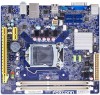
... connectors on the motherboard. Failure to unplug the power supply cord may result in serious damage to your computer : ■ It is a PCI Express x16 graphics card installed in order to avoid damage to the motherboard and CPU due to high temperature. Incorrect connections might damage the motherboard. ■ When handling the motherboard, avoid touching any , when connecting USB, audio, 1394a, RS232 COM, IrDA or S/PDIF cables to the internal connectors on the overclocking...
... connectors on the motherboard. Failure to unplug the power supply cord may result in serious damage to your computer : ■ It is a PCI Express x16 graphics card installed in order to avoid damage to the motherboard and CPU due to high temperature. Incorrect connections might damage the motherboard. ■ When handling the motherboard, avoid touching any , when connecting USB, audio, 1394a, RS232 COM, IrDA or S/PDIF cables to the internal connectors on the overclocking...
User manual
Page 6
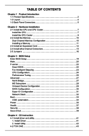
... Expansion Card 12 2-4 Install other Internal Connectors 13 2-5 Jumpers 16 Chapter 3 BIOS Setup Enter BIOS Setup 19 Main...20 F-center...22 Smart BIOS 22 Fox Intelligent Stepping 23 CPU Configuration 24 Performance Tuning 25 Advanced...27 North Bridge 27 ME Subsystem 28 Onboard Device Configuration 29 SATA Configuration 30 Super IO Configuration 31 Network Stack 32 Boot...33 CSM parameters 34 Power...35 Health...37 Security...38 Save & Exit 39 Chapter 4 CD Instruction 4-1 Install driver and utility 41 1. Install Driver...
... Expansion Card 12 2-4 Install other Internal Connectors 13 2-5 Jumpers 16 Chapter 3 BIOS Setup Enter BIOS Setup 19 Main...20 F-center...22 Smart BIOS 22 Fox Intelligent Stepping 23 CPU Configuration 24 Performance Tuning 25 Advanced...27 North Bridge 27 ME Subsystem 28 Onboard Device Configuration 29 SATA Configuration 30 Super IO Configuration 31 Network Stack 32 Boot...33 CSM parameters 34 Power...35 Health...37 Security...38 Save & Exit 39 Chapter 4 CD Instruction 4-1 Install driver and utility 41 1. Install Driver...

User manual
Page 12
PS/2 Keyboard Port Use the upper port to connect external display devices, such as an USB keyboard/mouse, USB printer, USB flash drive and etc. 5. VGA Port Use this port for USB devices such as monitor or LCD display. 4. LAN Type 100M 1000M Left: Active Status Description Status Off No Link Off Green Data Blinking Activity Orange Off No Link Off Green Data Blinking Activity Off ...
PS/2 Keyboard Port Use the upper port to connect external display devices, such as an USB keyboard/mouse, USB printer, USB flash drive and etc. 5. VGA Port Use this port for USB devices such as monitor or LCD display. 4. LAN Type 100M 1000M Left: Active Status Description Status Off No Link Off Green Data Blinking Activity Orange Off No Link Off Green Data Blinking Activity Off ...

User manual
Page 14
..., including the installation of the CPU, memory, power supply, slots, pin headers and the mounting of these modules. Caution should be exercised during the installation of jumpers. Please refer to the motherboard layout prior to any installation and read the contents in this chapter carefully. This chapter includes the following information : ■ Install the CPU and CPU Cooler ■ Install the Memory ■ Install an Expansion Card ■ Install other Internal Connectors ■ Jumpers
..., including the installation of the CPU, memory, power supply, slots, pin headers and the mounting of these modules. Caution should be exercised during the installation of jumpers. Please refer to the motherboard layout prior to any installation and read the contents in this chapter carefully. This chapter includes the following information : ■ Install the CPU and CPU Cooler ■ Install the Memory ■ Install an Expansion Card ■ Install other Internal Connectors ■ Jumpers

User manual
Page 20
... Removing a PCI Express x16 Graphics Card: • Installing a Graphics Card: Gently insert the graphics card into the slot. 4. Align the card with a screw. 5. After installing all expansion cards, replace the chassis cover. 6. If necessary, go to BIOS Setup to correctly install your expansion card(s). 7. Make sure the graphics card is fully seated in the expansion slot. 1. 2-3 Install an Expansion Card HARDWARE INSTALLATION ■ Make sure the motherboard supports the expansion card. ■ Always turn off the computer and unplug the power...
... Removing a PCI Express x16 Graphics Card: • Installing a Graphics Card: Gently insert the graphics card into the slot. 4. Align the card with a screw. 5. After installing all expansion cards, replace the chassis cover. 6. If necessary, go to BIOS Setup to correctly install your expansion card(s). 7. Make sure the graphics card is fully seated in the expansion slot. 1. 2-3 Install an Expansion Card HARDWARE INSTALLATION ■ Make sure the motherboard supports the expansion card. ■ Always turn off the computer and unplug the power...

User manual
Page 22
Speaker Header: SPEAKER The speaker connector is used to the chassis front panel IDE indicator LED. Hard Disk LED Connector (HDD-LED) Connect to connect speaker of the chassis. This 2-pin connector is blinking; sign. When the system gets into sleep mode (S1) , the LED is directional with +/- When the system is in operation (S0 status), the LED is directional with +/- It indicates the active status of the chassis. Reset Switch (RESET-SW) Attach the connector to the power button on the front panel of...
Speaker Header: SPEAKER The speaker connector is used to the chassis front panel IDE indicator LED. Hard Disk LED Connector (HDD-LED) Connect to connect speaker of the chassis. This 2-pin connector is blinking; sign. When the system gets into sleep mode (S1) , the LED is directional with +/- When the system is in operation (S0 status), the LED is directional with +/- It indicates the active status of the chassis. Reset Switch (RESET-SW) Attach the connector to the power button on the front panel of...

User manual
Page 24
... Setup to configure new system as "1". 2. The following content carefully prior to modifying any jumper on this motherboard, pin 1 can change the jumper settings on this motherboard by changing the jumper settings. Description of this motherboard to modify them. The shorting can prevent hazardous ESD (Electrical Static Discharge) problem. Jumper 1 1 Diagram 1 1 1 1 Definition Closed Open 1-2 2-3 Description Set Pin 1 and Pin 2 closed Set Pin 1 and Pin 2 Open Set Pin 1 and Pin 2 closed Set Pin 2 and Pin 3 closed Clear CMOS Header: CLR_CMOS The motherboard uses CMOS RAM...
... Setup to configure new system as "1". 2. The following content carefully prior to modifying any jumper on this motherboard, pin 1 can change the jumper settings on this motherboard by changing the jumper settings. Description of this motherboard to modify them. The shorting can prevent hazardous ESD (Electrical Static Discharge) problem. Jumper 1 1 Diagram 1 1 1 1 Definition Closed Open 1-2 2-3 Description Set Pin 1 and Pin 2 closed Set Pin 1 and Pin 2 Open Set Pin 1 and Pin 2 closed Set Pin 2 and Pin 3 closed Clear CMOS Header: CLR_CMOS The motherboard uses CMOS RAM...

User manual
Page 25
... set ME jumper to pins 2-3, you can disable the Intel® Management Engine function. 1 Enable 2 (Default) 3 1 Disable 2 3 PCH_ME_ENABLE Definition 1-2(default) 2-3 Description Set Pin 1 and Pin 2 closed Set Pin 2 and Pin 3 closed Function Enable ME function Disable ME function CAUTION Before flashing BIOS ROM, you can enable the Intel® Management Engine function. Intel® Management Engine (ME) is an embedded microcontroller located in Intel chipset. HARDWARE INSTALLATION Intel® ME Jumper: PCH_ME_ENABLE This motherboard uses this jumper...
... set ME jumper to pins 2-3, you can disable the Intel® Management Engine function. 1 Enable 2 (Default) 3 1 Disable 2 3 PCH_ME_ENABLE Definition 1-2(default) 2-3 Description Set Pin 1 and Pin 2 closed Set Pin 2 and Pin 3 closed Function Enable ME function Disable ME function CAUTION Before flashing BIOS ROM, you can enable the Intel® Management Engine function. Intel® Management Engine (ME) is an embedded microcontroller located in Intel chipset. HARDWARE INSTALLATION Intel® ME Jumper: PCH_ME_ENABLE This motherboard uses this jumper...

User manual
Page 27
... can be setup through this menu. Health This setup enables you can save or discard the changes and exit BIOS setup here. 20 However, it may cause problem if you to key in correct password before boot or access to read/change fan speeds, and displays temperatures and voltages of your system loading is heavy, set the boot device priority here. What you made. Use the arrow right/left keys to select a specific function and...
... can be setup through this menu. Health This setup enables you can save or discard the changes and exit BIOS setup here. 20 However, it may cause problem if you to key in correct password before boot or access to read/change fan speeds, and displays temperatures and voltages of your system loading is heavy, set the boot device priority here. What you made. Use the arrow right/left keys to select a specific function and...

User manual
Page 30
... Optimized Defaults F4: Save & Exit ESC/Right Click: Exit Version 2.15.1234. Smart BIOS Main F-center Advanced Boot Smart BIOS Power Health Smart Power LED Smart Boot Menu [Disabled] [Enabled] Security Save&Exit Smart Power LED Settings → ←: Select Screen ↑ ↓/Click: Select Item Enter/Dbl Click: Select +/-: Change Opt. F-center BIOS SETUP Main F-center Advanced Boot Fox Control Center Super BIOS Protect ▶ Smart BIOS ▶ Fox Intelligent Stepping ▶ CPU Configuration ▶ Performance Tuning Power Health [Enabled] Security...
... Optimized Defaults F4: Save & Exit ESC/Right Click: Exit Version 2.15.1234. Smart BIOS Main F-center Advanced Boot Smart BIOS Power Health Smart Power LED Smart Boot Menu [Disabled] [Enabled] Security Save&Exit Smart Power LED Settings → ←: Select Screen ↑ ↓/Click: Select Item Enter/Dbl Click: Select +/-: Change Opt. F-center BIOS SETUP Main F-center Advanced Boot Fox Control Center Super BIOS Protect ▶ Smart BIOS ▶ Fox Intelligent Stepping ▶ CPU Configuration ▶ Performance Tuning Power Health [Enabled] Security...

User manual
Page 31
... long On (1sec.), continuously. But if overclocking is a feature built on your computer through smart boot menu. On, 1/3sec. This also prevents user without password trying to get into your motherboard to indicate different states during Power On Self Test (POST). Copyright (C) 2012 American Megatrends, Inc. ► Spread Spectrum If you enabled this state enabled. System Status Normal No Memory No Display Post Error Message No CPU Fan Power LED...
... long On (1sec.), continuously. But if overclocking is a feature built on your computer through smart boot menu. On, 1/3sec. This also prevents user without password trying to get into your motherboard to indicate different states during Power On Self Test (POST). Copyright (C) 2012 American Megatrends, Inc. ► Spread Spectrum If you enabled this state enabled. System Status Normal No Memory No Display Post Error Message No CPU Fan Power LED...
User manual
Page 32
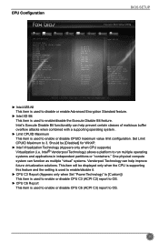
... disable or enable Advanced Encryption Standard feature. ► Intel XD Bit This item is used to OS. 25 CPU Configuration BIOS SETUP Main F-center Advanced Boot CPU Configuration CPU Brand Name: Genuine Intel(R) CPU @ 2.20GHz L1 Data Cache L1 Code Cache L2 Cache L3 Cache Processor Stepping Max CPU Speed Min CPU Speed Current CPU Speed Processor Cores Intel HT Technology Intel VT-x Technology Intel SMX Technology Intel AES-NI Intel XD Bit Limit CPUID Maximum Intel Virtualization Technology CPU C3 Report CPU...
... disable or enable Advanced Encryption Standard feature. ► Intel XD Bit This item is used to OS. 25 CPU Configuration BIOS SETUP Main F-center Advanced Boot CPU Configuration CPU Brand Name: Genuine Intel(R) CPU @ 2.20GHz L1 Data Cache L1 Code Cache L2 Cache L3 Cache Processor Stepping Max CPU Speed Min CPU Speed Current CPU Speed Processor Cores Intel HT Technology Intel VT-x Technology Intel SMX Technology Intel AES-NI Intel XD Bit Limit CPUID Maximum Intel Virtualization Technology CPU C3 Report CPU...

User manual
Page 33
... using XMP timing profile 1. [XMP Profile 2]- BIOS SETUP Performance Tuning Main F-center Advanced Boot ▶ CPU Configuration ▶ North Bridge Configuration Power Health Security Save&Exit CPU Configuration CAUTION → ←: Select Screen ↑ ↓/Click: Select Item Enter/Dbl Click: Select +/-: Change Opt. Copyright (C) 2012 American Megatrends, Inc. Please refer to Intel Website for more information. ► Turbo Mode Turbo mode allows processor cores to set to "Manual". ► Memory Clock...
... using XMP timing profile 1. [XMP Profile 2]- BIOS SETUP Performance Tuning Main F-center Advanced Boot ▶ CPU Configuration ▶ North Bridge Configuration Power Health Security Save&Exit CPU Configuration CAUTION → ←: Select Screen ↑ ↓/Click: Select Item Enter/Dbl Click: Select +/-: Change Opt. Copyright (C) 2012 American Megatrends, Inc. Please refer to Intel Website for more information. ► Turbo Mode Turbo mode allows processor cores to set to "Manual". ► Memory Clock...

User manual
Page 36
... Version It displays the current ME version. 29 BIOS SETUP These items display the memory size installed on each slot. ► Integrated Graphics This item allows you to determine whether to allocate memory for maximum 2D/3D graphics performance. Options: [Auto], [Manual]. [Auto]-Auto the integrated graphics controller. [Manual]- ME Subsystem Main F-center Advanced Boot Intel ME Subsystem Configuration ME Version Power Health 8.1.2.1318 Security Save&Exit → ←: Select Screen ↑ ↓/Click: Select Item Enter/Dbl...
... Version It displays the current ME version. 29 BIOS SETUP These items display the memory size installed on each slot. ► Integrated Graphics This item allows you to determine whether to allocate memory for maximum 2D/3D graphics performance. Options: [Auto], [Manual]. [Auto]-Auto the integrated graphics controller. [Manual]- ME Subsystem Main F-center Advanced Boot Intel ME Subsystem Configuration ME Version Power Health 8.1.2.1318 Security Save&Exit → ←: Select Screen ↑ ↓/Click: Select Item Enter/Dbl...

User manual
Page 37
...a USB keyboard or mouse, set to enabled. [Enabled]: This option will enable the legacy USB support. [Disabled]: This option will keep USB devices available only for EFI applications. ► Azalia HD Audio controller This item is used to enable the support for USB devices on legacy OS. F1: General Help F2: Previous Values F3: Optimized Defaults F4: Save & Exit ESC/Right Click: Exit Version 2.15.1234. BIOS SETUP Onboard Device Configuration Main F-center Advanced Boot Power Health Security Save&Exit Onboard Device Configuration Onboard LAN Controller Onboard USB Controller Legacy...
...a USB keyboard or mouse, set to enabled. [Enabled]: This option will enable the legacy USB support. [Disabled]: This option will keep USB devices available only for EFI applications. ► Azalia HD Audio controller This item is used to enable the support for USB devices on legacy OS. F1: General Help F2: Previous Values F3: Optimized Defaults F4: Save & Exit ESC/Right Click: Exit Version 2.15.1234. BIOS SETUP Onboard Device Configuration Main F-center Advanced Boot Power Health Security Save&Exit Onboard Device Configuration Onboard LAN Controller Onboard USB Controller Legacy...

User manual
Page 38
... motherboard supporting AHCI, and you have a SATA device, which also supports AHCI, then you can select IDE option to have fair performance (only PATA, SATA level), or you can select AHCI to get its specification. Copyright (C) 2012 American Megatrends, Inc. ► Onboard SATA Controller This item is used to enable or disable the onboard SATA controller. ► Onboard SATA Mode This item is used to show the SATA Device information. 31 SATA Configuration BIOS SETUP Main F-center Advanced Boot Power Health Security Save&Exit SATA Configuration Onboard SATA Controller...
... motherboard supporting AHCI, and you have a SATA device, which also supports AHCI, then you can select IDE option to have fair performance (only PATA, SATA level), or you can select AHCI to get its specification. Copyright (C) 2012 American Megatrends, Inc. ► Onboard SATA Controller This item is used to enable or disable the onboard SATA controller. ► Onboard SATA Mode This item is used to show the SATA Device information. 31 SATA Configuration BIOS SETUP Main F-center Advanced Boot Power Health Security Save&Exit SATA Configuration Onboard SATA Controller...

User manual
Page 41
...USB KEY Drive BBS Priorities ▶ UEFI Boot Drive BBS Prioriies Power Health [On] [Enabled] [Disabled] [Enabled] [Hard Disk] [CD/DVD] [USB Floppy] [USB CD/DVD] [USB Hard Disk] [USB KEY] [Network] [UEFI] Security Save&Exit Select the keyboard NumLock state → ←: Select Screen ↑ ↓/Click: Select Item Enter/Dbl Click: Select +/-: Change Opt. The available settings are: On (default) and Off. ► Quiet Boot This item is used to enable/disable the quiet boot. [Disabled] : Displays the normal POST messages. [Enabled] : Displays OEM customer logo instead of POST...
...USB KEY Drive BBS Priorities ▶ UEFI Boot Drive BBS Prioriies Power Health [On] [Enabled] [Disabled] [Enabled] [Hard Disk] [CD/DVD] [USB Floppy] [USB CD/DVD] [USB Hard Disk] [USB KEY] [Network] [UEFI] Security Save&Exit Select the keyboard NumLock state → ←: Select Screen ↑ ↓/Click: Select Item Enter/Dbl Click: Select +/-: Change Opt. The available settings are: On (default) and Off. ► Quiet Boot This item is used to enable/disable the quiet boot. [Disabled] : Displays the normal POST messages. [Enabled] : Displays OEM customer logo instead of POST...

User manual
Page 45
... time, Instruction Alarm don't clear, it will appear. Default value is [Disabled]. ► System Smart Fan Control This option is used to enable or disable CPU smart fan function. F1: General Help F2: Previous Values F3: Optimized Defaults F4: Save & Exit ESC/Right Click: Exit Version 2.15.1234. Default value 38 BIOS SETUP Health Main F-center Advanced Boot Case Open Warning CPU Temperature System Temperature CPU Fan Speed System Fan Speed CPU Vcore VDDR +12V SYS +5V SYS VBAT CPU Smart Fan Control System Smart Fan Control Power Health [Disabled...
... time, Instruction Alarm don't clear, it will appear. Default value is [Disabled]. ► System Smart Fan Control This option is used to enable or disable CPU smart fan function. F1: General Help F2: Previous Values F3: Optimized Defaults F4: Save & Exit ESC/Right Click: Exit Version 2.15.1234. Default value 38 BIOS SETUP Health Main F-center Advanced Boot Case Open Warning CPU Temperature System Temperature CPU Fan Speed System Fan Speed CPU Vcore VDDR +12V SYS +5V SYS VBAT CPU Smart Fan Control System Smart Fan Control Power Health [Disabled...

User manual
Page 46
... used to enable or disable protect HDD MBR from avoiding destroied by virus. ► Secure Boot menu Press to go to its submenu. 39 Only when there exists a Administrator password, then this setting can be 1 to 20 characters long. → ←: Select Screen ↑ ↓/Click: Select Item Enter/Dbl Click: Select +/-: Change Opt. Security BIOS SETUP Main F-center Advanced Boot Power Health Security Save&Exit Security configuration...
... used to enable or disable protect HDD MBR from avoiding destroied by virus. ► Secure Boot menu Press to go to its submenu. 39 Only when there exists a Administrator password, then this setting can be 1 to 20 characters long. → ←: Select Screen ↑ ↓/Click: Select Item Enter/Dbl Click: Select +/-: Change Opt. Security BIOS SETUP Main F-center Advanced Boot Power Health Security Save&Exit Security configuration...

User manual
Page 49
Install Driver Use these options to Install 42 After that, you can click "One Click Setup" and then choose the items you want to install, or you want to install all the drivers for your system. You must click "Intel Chipset Driver" to install it first. Manual Installation Step by Step Automatic Installation by One Click Drop to System Tray Exit the program Visit Foxconn's Show Utilities Show Drivers Browse CD View User's Manual website Choose the items you can click on each individual driver to install it manually. CD INSTRUCTION 4-1 Install driver and utility 1.
Install Driver Use these options to Install 42 After that, you can click "One Click Setup" and then choose the items you want to install, or you want to install all the drivers for your system. You must click "Intel Chipset Driver" to install it first. Manual Installation Step by Step Automatic Installation by One Click Drop to System Tray Exit the program Visit Foxconn's Show Utilities Show Drivers Browse CD View User's Manual website Choose the items you can click on each individual driver to install it manually. CD INSTRUCTION 4-1 Install driver and utility 1.


