User manual
Page 5
... installing or removing CPU, memory, expansion cards or other peripherals. Also, make sure there are uncertain about any , when connecting USB, audio, 1394a, RS232 COM, IrDA or S/PDIF cables to the internal connectors on the motherboard, make sure the power supply AC input voltage setting has been configured to the local standard. ■ To prevent damage to the motherboard, do not allow screws to come in your system. Failure...
... installing or removing CPU, memory, expansion cards or other peripherals. Also, make sure there are uncertain about any , when connecting USB, audio, 1394a, RS232 COM, IrDA or S/PDIF cables to the internal connectors on the motherboard, make sure the power supply AC input voltage setting has been configured to the local standard. ■ To prevent damage to the motherboard, do not allow screws to come in your system. Failure...

User manual
Page 7
... Windows XP 93 Limit Setting 50 5. Fan Control 53 4-3 FOX LiveUpdate 54 1. Online Update 56 3. Reset Disks to Install Serial ATA Hard Disks 67 5-4 Create a RAID driver diskette 68 5-5 BIOS Configuration 69 5-6 Create RAID in BIOS 69 1. 4. Fan Page - Delete RAID Volume 85 4. Configure 59 4. Recovery Volume Options 91 6. About & Help 61 4-4 FOX LOGO 62 4-5 FOX DMI 63 4-6 Smart charger 63 Chapter 5 RAID Configuration 5-1 RAID Configuration Introduction 65 5-2 Intel® Rapid Storage Technology enterprise 67 5-3 Steps to Non-RAID 86 5. Voltage...
... Windows XP 93 Limit Setting 50 5. Fan Control 53 4-3 FOX LiveUpdate 54 1. Online Update 56 3. Reset Disks to Install Serial ATA Hard Disks 67 5-4 Create a RAID driver diskette 68 5-5 BIOS Configuration 69 5-6 Create RAID in BIOS 69 1. 4. Fan Page - Delete RAID Volume 85 4. Configure 59 4. Recovery Volume Options 91 6. About & Help 61 4-4 FOX LOGO 62 4-5 FOX DMI 63 4-6 Smart charger 63 Chapter 5 RAID Configuration 5-1 RAID Configuration Introduction 65 5-2 Intel® Rapid Storage Technology enterprise 67 5-3 Steps to Non-RAID 86 5. Voltage...

User manual
Page 12
...port supports DVI-D specification. Connect a monitor that supports DVI-D connection to install the USB 3.0 driver in the Driver CD before using it. 5 USB 3.0 Port The USB port supports the USB 3.0/2.0/1.0 specification. Use this port for USB devices such as monitor or LCD display. 4. Use this port for USB devices such as an USB keyboard/mouse, USB printer, USB flash drive and etc. 1-3 Back Panel Connectors PS/2 Keyboard Port 1 PRODUCT INTRODUCTION USB 3.0 Port 6 LAN Port 7 Line In Line Out Microphone In 2 USB 2.0 Port 3 VGA Port 4 HDMI Port (H77MXV) 2 USB 2.0 Port 8 Audio...
...port supports DVI-D specification. Connect a monitor that supports DVI-D connection to install the USB 3.0 driver in the Driver CD before using it. 5 USB 3.0 Port The USB port supports the USB 3.0/2.0/1.0 specification. Use this port for USB devices such as monitor or LCD display. 4. Use this port for USB devices such as an USB keyboard/mouse, USB printer, USB flash drive and etc. 1-3 Back Panel Connectors PS/2 Keyboard Port 1 PRODUCT INTRODUCTION USB 3.0 Port 6 LAN Port 7 Line In Line Out Microphone In 2 USB 2.0 Port 3 VGA Port 4 HDMI Port (H77MXV) 2 USB 2.0 Port 8 Audio...
User manual
Page 20
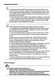
... correctly install your expansion card in your card. Make sure the graphics card is fully seated in the slot. 3. Turn on the card are completely inserted into the PCI Express x16 slot. Installing and Removing a PCI Express x16 Graphics Card: • Installing a Graphics Card: Gently insert the graphics card into the slot. 4. If necessary, go to BIOS Setup to prevent hardware damage. Locate an expansion slot that supports your operating system. After installing all expansion cards, replace the chassis cover. 6. Install the driver provided...
... correctly install your expansion card in your card. Make sure the graphics card is fully seated in the slot. 3. Turn on the card are completely inserted into the PCI Express x16 slot. Installing and Removing a PCI Express x16 Graphics Card: • Installing a Graphics Card: Gently insert the graphics card into the slot. 4. If necessary, go to BIOS Setup to prevent hardware damage. Locate an expansion slot that supports your operating system. After installing all expansion cards, replace the chassis cover. 6. Install the driver provided...

User manual
Page 22
Hard Disk LED Connector (HDD-LED) Connect to connect speaker of the case; This 2-pin connector is directional with +/- Power Switch Connector (PWR-SW) Connect to a security switch on the front panel of the hard disks. The system can be turned on the front panel of the chassis. PWR-LED - When the system is in S3/S4 sleep state or power off mode (S5), the LED is off rather than using the power supply button. When the system is in operation (S0 status...
Hard Disk LED Connector (HDD-LED) Connect to connect speaker of the case; This 2-pin connector is directional with +/- Power Switch Connector (PWR-SW) Connect to a security switch on the front panel of the hard disks. The system can be turned on the front panel of the chassis. PWR-LED - When the system is in S3/S4 sleep state or power off mode (S5), the LED is off rather than using the power supply button. When the system is in operation (S0 status...
User manual
Page 25
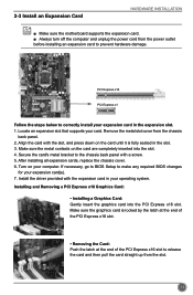
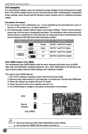
... on the two pins to clear CMOS data are : 1. Turn off the computer, unplug the power cord from pins 2-3, put it on. 5. Remove jumper cap from the power outlet. 2. For any jumper setting. The steps to temporarily short them . HARDWARE INSTALLATION 2-5 Jumpers For some features needed, users can change the jumper settings on this motherboard by changing the jumper settings. Return the setting to its original with pins 2-3 closed Clear CMOS Jumper: CLR_CMOS The motherboard uses CMOS RAM to store the...
... on the two pins to clear CMOS data are : 1. Turn off the computer, unplug the power cord from pins 2-3, put it on. 5. Remove jumper cap from the power outlet. 2. For any jumper setting. The steps to temporarily short them . HARDWARE INSTALLATION 2-5 Jumpers For some features needed, users can change the jumper settings on this motherboard by changing the jumper settings. Return the setting to its original with pins 2-3 closed Clear CMOS Jumper: CLR_CMOS The motherboard uses CMOS RAM to store the...

User manual
Page 26
... located in Intel chipset. HARDWARE INSTALLATION Intel® ME Jumper: PCH_ME_ENABLE This motherboard uses this jumper to improve management of corporate assets. It provides latest IT management features such as Intel® AMT, that allows to enable or disable Intel® Management Engine function. Set the jumper to pins 1-2, you need to set ME jumper to pins 2-3, you can disable the Intel® Management Engine function. 1 Enable 2 (Default) 3 1 Disable...
... located in Intel chipset. HARDWARE INSTALLATION Intel® ME Jumper: PCH_ME_ENABLE This motherboard uses this jumper to improve management of corporate assets. It provides latest IT management features such as Intel® AMT, that allows to enable or disable Intel® Management Engine function. Set the jumper to pins 1-2, you need to set ME jumper to pins 2-3, you can disable the Intel® Management Engine function. 1 Enable 2 (Default) 3 1 Disable...

User manual
Page 28
... from the change fan speeds, and displays temperatures and voltages of your CPU/System. Security The Administrator/User password can be set the boot device priority and enable "Quiet Boot" feature here. What you have more memory or I/O cards installed. They all can be viewed or set up through this menu. However, it may offer better performance in correct password before boot or access to prevent unauthorized use of your computer. Power All the...
... from the change fan speeds, and displays temperatures and voltages of your CPU/System. Security The Administrator/User password can be set the boot device priority and enable "Quiet Boot" feature here. What you have more memory or I/O cards installed. They all can be viewed or set up through this menu. However, it may offer better performance in correct password before boot or access to prevent unauthorized use of your computer. Power All the...
User manual
Page 33
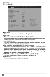
... item is used to enable/disable the Execute Disable Bit feature. Set Limit CPUID Maximum to run multiple operating systems and applications in independent partitions or "containers." BIOS SETUP CPU Configuration Aptio Setup Utility - F-Center CPU Configuration Intel AES-NI CPU Brand Name: Genuine Intel(R) CPU @ 1.80GHz L1 Data Cache L1 Code Cache L2 Cache L3 Cache Processor Stepping Max CPU Speed Min CPU Speed CPU Speed Processor Cores Intel HT Technology Intel VT-x Technology Intel SMX Technology Intel AES...
... item is used to enable/disable the Execute Disable Bit feature. Set Limit CPUID Maximum to run multiple operating systems and applications in independent partitions or "containers." BIOS SETUP CPU Configuration Aptio Setup Utility - F-Center CPU Configuration Intel AES-NI CPU Brand Name: Genuine Intel(R) CPU @ 1.80GHz L1 Data Cache L1 Code Cache L2 Cache L3 Cache Processor Stepping Max CPU Speed Min CPU Speed CPU Speed Processor Cores Intel HT Technology Intel VT-x Technology Intel SMX Technology Intel AES...
User manual
Page 34
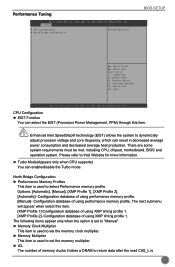
.... ► Turbo Mode(Appears only when CPU supports) You can enable/disable the Turbo mode. Please refer to dynamically adjust processor voltage and core frequency, which can select the EIST (Processor Power Management, PPM) through this item. [XMP Profile 1]-Configuration database of using XMP timing profile 1. [XMP Profile 2]- Configuration database of using performance memory profile. There are some system requirements must be met, including CPU, chipset, motherboard, BIOS and operation system...
.... ► Turbo Mode(Appears only when CPU supports) You can enable/disable the Turbo mode. Please refer to dynamically adjust processor voltage and core frequency, which can select the EIST (Processor Power Management, PPM) through this item. [XMP Profile 1]-Configuration database of using XMP timing profile 1. [XMP Profile 2]- Configuration database of using performance memory profile. There are some system requirements must be met, including CPU, chipset, motherboard, BIOS and operation system...
User manual
Page 37
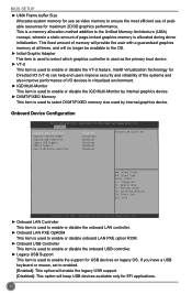
... onboard LAN PXE option ROM. ► Onboard USB Controller This item is used to enable or disable the onboard USB controller. ► Legacy USB Support This item is used by internal graphics device. Advanced Onboard LAN Controller Onboard LAN PXE OpROM Onboard USB Controller Legacy USB Support USB3.0 Support Azalia HD Audio controller [Enabled] [Disabled] [Enabled] [Enabled] [Enabled] [Enabled] Onboard LAN Controller → ←: Select Screen ↑ ↓: Select Item Enter: Select +/-: Change Opt. BIOS SETUP ► UMA Frame buffer Size Allocates system memory...
... onboard LAN PXE option ROM. ► Onboard USB Controller This item is used to enable or disable the onboard USB controller. ► Legacy USB Support This item is used by internal graphics device. Advanced Onboard LAN Controller Onboard LAN PXE OpROM Onboard USB Controller Legacy USB Support USB3.0 Support Azalia HD Audio controller [Enabled] [Disabled] [Enabled] [Enabled] [Enabled] [Enabled] Onboard LAN Controller → ←: Select Screen ↑ ↓: Select Item Enter: Select +/-: Change Opt. BIOS SETUP ► UMA Frame buffer Size Allocates system memory...

User manual
Page 38
... system software and the host controller hardware. BIOS SETUP SATA Configuration Aptio Setup Utility - This configures the SATA ports to its best performance. [RAID] - Copyright (C) 2011 American Megatrends, Inc. ► Onboard SATA Controller This item is used to enable or disable the onboard SATA controller. ► Onboard SATA Mode This item is used to enable or disable the USB 3.0. ► Azalia HD Audio controller This item is enable oe disable the Azalia HD Audio Controller. F1: General Help F2: Previous Values F3: Optimized Defaults F4...
... system software and the host controller hardware. BIOS SETUP SATA Configuration Aptio Setup Utility - This configures the SATA ports to its best performance. [RAID] - Copyright (C) 2011 American Megatrends, Inc. ► Onboard SATA Controller This item is used to enable or disable the onboard SATA controller. ► Onboard SATA Mode This item is used to enable or disable the USB 3.0. ► Azalia HD Audio controller This item is enable oe disable the Azalia HD Audio Controller. F1: General Help F2: Previous Values F3: Optimized Defaults F4...
User manual
Page 40
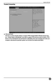
... [Disabled]. Default option is used to decide whether to [Enabled], then save changing and reset your computer, otherwise the operation system can not show Security Device. F1: General Help F2: Previous Values F3: Optimized Defaults F4: Save & Exit ESC: Exit Version 2.14.1219. O.S. tion. Advanced TPM Configuration TPM SUPPORT Current TPM Status Information NO TPM Hardware [Disabled] Enables or Disables BIOS support for security device. Trusted Computing BIOS SETUP Aptio Setup Utility...
... [Disabled]. Default option is used to decide whether to [Enabled], then save changing and reset your computer, otherwise the operation system can not show Security Device. F1: General Help F2: Previous Values F3: Optimized Defaults F4: Save & Exit ESC: Exit Version 2.14.1219. O.S. tion. Advanced TPM Configuration TPM SUPPORT Current TPM Status Information NO TPM Hardware [Disabled] Enables or Disables BIOS support for security device. Trusted Computing BIOS SETUP Aptio Setup Utility...

User manual
Page 44
....074 V : +5.146 V CPU Warning Temperature CPU Shutdowm Temperature CPU Smart Fan Control System Smart Fan Control [Disabled] [Disabled] [Disabled] [Disabled] → ←: Select Screen ↑ ↓: Select Item Enter: Select +/-: Change Opt. F1: General Help F2: Previous Values F3: Optimized Defaults F4: Save & Exit ESC: Exit BIOS SETUP Version 2.02.1205. "Smart Fan Automatic Mode" is the principle figure of CPU is used to enable or disable case open warning function. ► CPU Temperature These items show the current CPU temperature detected automatically...
....074 V : +5.146 V CPU Warning Temperature CPU Shutdowm Temperature CPU Smart Fan Control System Smart Fan Control [Disabled] [Disabled] [Disabled] [Disabled] → ←: Select Screen ↑ ↓: Select Item Enter: Select +/-: Change Opt. F1: General Help F2: Previous Values F3: Optimized Defaults F4: Save & Exit ESC: Exit BIOS SETUP Version 2.02.1205. "Smart Fan Automatic Mode" is the principle figure of CPU is used to enable or disable case open warning function. ► CPU Temperature These items show the current CPU temperature detected automatically...
User manual
Page 45
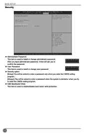
...enable/disable boot sector write protection. 38 Administator Password HDD BOOTSector Write [Normal] → ←: Select Screen ↑ ↓: Select Item Enter: Select +/-: Change Opt. Main F-Center Advanced Boot Power Health SSeeccuurriittyy Save & Exit Password Description Administrator Password User Password Set Administrator Password. Copyright (C) 2011 American Megatrends, Inc. ► Administrator Password This item is used to install or change user password. ► Security option [Setup]: You will be asked to enter a password only when you enter the CMOS...
...enable/disable boot sector write protection. 38 Administator Password HDD BOOTSector Write [Normal] → ←: Select Screen ↑ ↓: Select Item Enter: Select +/-: Change Opt. Main F-Center Advanced Boot Power Health SSeeccuurriittyy Save & Exit Password Description Administrator Password User Password Set Administrator Password. Copyright (C) 2011 American Megatrends, Inc. ► Administrator Password This item is used to install or change user password. ► Security option [Setup]: You will be asked to enter a password only when you enter the CMOS...
User manual
Page 48
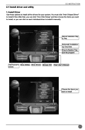
Install Driver Use these options to Install 41 Manual Installation Step by Step Automatic Installation by One Click Drop to System Tray Exit the program Visit Foxconn's Show Utilities Show Drivers Browse CD View User's Manual website Choose the items you can click "One Click Setup" and then choose the items you want to install, or you want to install all the drivers for your system. 4-1 Install driver and utility CD INSTRUCTION 1. You must click "Intel Chipset Driver" to install it first. After that, you can click on each individual driver to install it manually.
Install Driver Use these options to Install 41 Manual Installation Step by Step Automatic Installation by One Click Drop to System Tray Exit the program Visit Foxconn's Show Utilities Show Drivers Browse CD View User's Manual website Choose the items you can click "One Click Setup" and then choose the items you want to install, or you want to install all the drivers for your system. 4-1 Install driver and utility CD INSTRUCTION 1. You must click "Intel Chipset Driver" to install it first. After that, you can click on each individual driver to install it manually.
User manual
Page 73
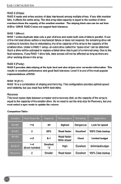
... of RAID. RAID 1 (Mirror) RAID 1 writes duplicate data onto a pair of drives and reads both sets of data interleaved among multiple drives. Under a RAID 1 setup, an extra drive called the "spare drive" can be affected as long as there are other working drives in excellent performance and good fault tolerance. This configuration provides optimal speed and reliability, but you need to set from 4KB to update the...
... of RAID. RAID 1 (Mirror) RAID 1 writes duplicate data onto a pair of drives and reads both sets of data interleaved among multiple drives. Under a RAID 1 setup, an extra drive called the "spare drive" can be affected as long as there are other working drives in excellent performance and good fault tolerance. This configuration provides optimal speed and reliability, but you need to set from 4KB to update the...

User manual
Page 76
... enter Configuration Utility. Delete RAID Volume 5. Physical Devices: ID Device Model 0 ST3320418AS 1 ST3160815AS Serial # 9VM8Y4D8 5RX4M04N Size Type/Status(Vol ID) 298.0GB Non-RAID Disk 149.0GB Non-RAID Disk Select ESC]-Exit ENTER]-Select Menu 69 Check if the diskette contains the driver files. Install SATA hard disks into this floppy diskette to provide driver for additional specific devices, for example, a RAID device. 10. Create RAID Volume 4. Reset Disks to Chapter 3 BIOS Setup) 3. Set the "SATA Mode" to "RAID Mode". (Please refer to Non-RAID...
... enter Configuration Utility. Delete RAID Volume 5. Physical Devices: ID Device Model 0 ST3320418AS 1 ST3160815AS Serial # 9VM8Y4D8 5RX4M04N Size Type/Status(Vol ID) 298.0GB Non-RAID Disk 149.0GB Non-RAID Disk Select ESC]-Exit ENTER]-Select Menu 69 Check if the diskette contains the driver files. Install SATA hard disks into this floppy diskette to provide driver for additional specific devices, for example, a RAID device. 10. Create RAID Volume 4. Reset Disks to Chapter 3 BIOS Setup) 3. Set the "SATA Mode" to "RAID Mode". (Please refer to Non-RAID...

User manual
Page 99
...of Recovery change from floppy drive. 5. A lAl lRl RigihgthstsRReseesrevrevde.d. [ MAIN MENU ] 1. Recover Volume Options 2. Shut down the computer, remove the Non-RAID disk, and we will enter BIOS setup. 3. Intel(IRn)teMl(aRt)riRx aSptoidraSgteorMagaenaTgeecrhnoopltoiogny R -O UMpvti5o.n0.R0O.1M01-11I1C.H0.98R.12w0R4A I D 5 Copyright(C) 2003-1014 IInntteell CCoorrppoorraattiioonn. Recovery Volume Options 2. Delete RAID Volume 5. Reset Disks to start Windows installation. 92 Remove any diskette from Contious Update mode to the main menu. Create...
...of Recovery change from floppy drive. 5. A lAl lRl RigihgthstsRReseesrevrevde.d. [ MAIN MENU ] 1. Recover Volume Options 2. Shut down the computer, remove the Non-RAID disk, and we will enter BIOS setup. 3. Intel(IRn)teMl(aRt)riRx aSptoidraSgteorMagaenaTgeecrhnoopltoiogny R -O UMpvti5o.n0.R0O.1M01-11I1C.H0.98R.12w0R4A I D 5 Copyright(C) 2003-1014 IInntteell CCoorrppoorraattiioonn. Recovery Volume Options 2. Delete RAID Volume 5. Reset Disks to start Windows installation. 92 Remove any diskette from Contious Update mode to the main menu. Create...
User manual
Page 101
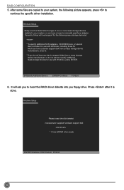
... done. S=Specify Additional Device ENTER=Continue F3=Exit 6. Currently, Setup will ask you to manually specify an adapter. Windows Setup Please insert the disk labeled manufacturer-supplied hardware support disk into you floppy drive. Windows Setup Setup could not determine the type of one or more mass storage devices installed in your system, the following mass storage device(s): * To specify additional SCSI adapters, CD-ROM drivers, or special disk controllers for use with Windows, including those for...
... done. S=Specify Additional Device ENTER=Continue F3=Exit 6. Currently, Setup will ask you to manually specify an adapter. Windows Setup Please insert the disk labeled manufacturer-supplied hardware support disk into you floppy drive. Windows Setup Setup could not determine the type of one or more mass storage devices installed in your system, the following mass storage device(s): * To specify additional SCSI adapters, CD-ROM drivers, or special disk controllers for use with Windows, including those for...


