
User manual
Page 6
... 11 Dual Channel Memory Configuration 11 Installing a Memory 11 2-3 Install an Expansion Card 13 2-4 Install other Internal Connectors 14 Chapter 3 BIOS Setup Enter BIOS Setup 21 Main...22 F-Center...24 Smart BIOS 24 Fox Intelligent Stepping 25 CPU Configuration 26 Performance Tuning 27 Advanced...29 North Bridge 29 Onboard Device Configuration 30 SATA...
... 11 Dual Channel Memory Configuration 11 Installing a Memory 11 2-3 Install an Expansion Card 13 2-4 Install other Internal Connectors 14 Chapter 3 BIOS Setup Enter BIOS Setup 21 Main...22 F-Center...24 Smart BIOS 24 Fox Intelligent Stepping 25 CPU Configuration 26 Performance Tuning 27 Advanced...29 North Bridge 29 Onboard Device Configuration 30 SATA...

User manual
Page 7
... Create RAID Volume 70 3. Exit RAID BIOS 92 5-7 Install a New Windows XP 93 Configure 59 4. Voltage Control (Optional 53 6. Reset Disks to Install Serial ATA Hard Disks 67 5-4 Create a RAID driver diskette 68 5-5 BIOS Configuration 69 5-6 Create RAID in BIOS 69 1. Fan Control 53 4-3 FOX... LiveUpdate 54 1. Local Update 54 2. Enter RAID BIOS Setup 69 2. About & Help 61 4-4 FOX LOGO 62 4-5 FOX DMI 63 4-6 ...
... Create RAID Volume 70 3. Exit RAID BIOS 92 5-7 Install a New Windows XP 93 Configure 59 4. Voltage Control (Optional 53 6. Reset Disks to Install Serial ATA Hard Disks 67 5-4 Create a RAID driver diskette 68 5-5 BIOS Configuration 69 5-6 Create RAID in BIOS 69 1. Fan Control 53 4-3 FOX... LiveUpdate 54 1. Local Update 54 2. Enter RAID BIOS Setup 69 2. About & Help 61 4-4 FOX LOGO 62 4-5 FOX DMI 63 4-6 ...

User manual
Page 15
..., hard drive, etc. The CPU cannot be set the frequency beyond hardware specifications since it does not meet the standard requirements for HT Technology ■ A BIOS that supports HT Technology and has it enabled Install the CPU Locate the alignment keys on the motherboard CPU socket and the notches on the...
..., hard drive, etc. The CPU cannot be set the frequency beyond hardware specifications since it does not meet the standard requirements for HT Technology ■ A BIOS that supports HT Technology and has it enabled Install the CPU Locate the alignment keys on the motherboard CPU socket and the notches on the...
User manual
Page 20
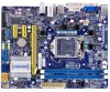
...the PCI Express x16 slot. • Removing the Card: Push the latch at the end of the PCI Express x16 slot to make any required BIOS changes for your expansion card in the slot. 3. Installing and Removing a PCI Express x16 Graphics Card: • Installing a Graphics Card: Gently insert... the graphics card into the slot. 4. After installing all expansion cards, replace the chassis cover. 6. If necessary, go to BIOS Setup to release the card and then pull the card straight up from the slot. 13 Remove the metal slot cover from the chassis back...
...the PCI Express x16 slot. • Removing the Card: Push the latch at the end of the PCI Express x16 slot to make any required BIOS changes for your expansion card in the slot. 3. Installing and Removing a PCI Express x16 Graphics Card: • Installing a Graphics Card: Gently insert... the graphics card into the slot. 4. After installing all expansion cards, replace the chassis cover. 6. If necessary, go to BIOS Setup to release the card and then pull the card straight up from the slot. 13 Remove the metal slot cover from the chassis back...

User manual
Page 24
... off after the system enters S3, S4 and S5 sleeping states. Fan Connectors: CPU_FAN, SYS_FAN The fan speed can be controlled and monitored in the BIOS Setup. CIR Header: CIR This connector supports infrared wireless trans mitting and receiving device. 5VSB_SYS 1 EMPTY 2 CIRRX 3 CIRTX 4 GND 5 CIR TPM Connector : TPM The...
... off after the system enters S3, S4 and S5 sleeping states. Fan Connectors: CPU_FAN, SYS_FAN The fan speed can be controlled and monitored in the BIOS Setup. CIR Header: CIR This connector supports infrared wireless trans mitting and receiving device. 5VSB_SYS 1 EMPTY 2 CIRRX 3 CIRTX 4 GND 5 CIR TPM Connector : TPM The...
User manual
Page 25
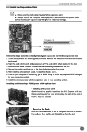
...2 closed Set Pin 1 and Pin 2 Open Set Pin 1 and Pin 2 closed Set Pin 2 and Pin 3 closed . 4. The steps to factory default when the BIOS settings were mistakenly modified. This will clear CMOS data. 3. For any jumper setting. It can change the jumper settings on this motherboard, pin 1 can also...be identified by a screwdriver for a few seconds, but using jumper cap is turned on . 5. Clear CMOS data is simply labeled as "1". 2. Go to BIOS Setup to temporarily short them . Description of this manual, pin 1 is the fast way to go back to clear CMOS data are : 1. The shorting ...
...2 closed Set Pin 1 and Pin 2 Open Set Pin 1 and Pin 2 closed Set Pin 2 and Pin 3 closed . 4. The steps to factory default when the BIOS settings were mistakenly modified. This will clear CMOS data. 3. For any jumper setting. It can change the jumper settings on this motherboard, pin 1 can also...be identified by a screwdriver for a few seconds, but using jumper cap is turned on . 5. Clear CMOS data is simply labeled as "1". 2. Go to BIOS Setup to temporarily short them . Description of this manual, pin 1 is the fast way to go back to clear CMOS data are : 1. The shorting ...

User manual
Page 26
... 2 (Default) 3 1 Disable 2 3 PCH_ME_ENABLE Definition 1-2(default) 2-3 Description Set Pin 1 and Pin 2 closed Set Pin 2 and Pin 3 closed Function Enable ME function Disable ME function N Before flashing BIOS ROM, you can enable the Intel® Management Engine function. CAUTIO 19
... 2 (Default) 3 1 Disable 2 3 PCH_ME_ENABLE Definition 1-2(default) 2-3 Description Set Pin 1 and Pin 2 closed Set Pin 2 and Pin 3 closed Function Enable ME function Disable ME function N Before flashing BIOS ROM, you can enable the Intel® Management Engine function. CAUTIO 19

User manual
Page 27
You want to change the default CMOS settings. This chapter includes the following cases occur: 1. An error message appears on the screen during the system Power On Self Test (POST) process. 2. You have to run the Setup Program when the following information : ■ Enter BIOS Setup ■ Main ■ F-Center ■ Advanced ■ Boot ■ Power ■ Health ■ Security ■ Save & Exit Chapter 3 BIOS Setup This chapter tells how to change system settings through the BIOS Setup menus. Detailed descriptions of the BIOS parameters are also provided.
You want to change the default CMOS settings. This chapter includes the following cases occur: 1. An error message appears on the screen during the system Power On Self Test (POST) process. 2. You have to run the Setup Program when the following information : ■ Enter BIOS Setup ■ Main ■ F-Center ■ Advanced ■ Boot ■ Power ■ Health ■ Security ■ Save & Exit Chapter 3 BIOS Setup This chapter tells how to change system settings through the BIOS Setup menus. Detailed descriptions of the BIOS parameters are also provided.

User manual
Page 28
... setting for your current system. Advanced The values for any damage which resulted from the change you to read/change the default values in the BIOS Setup, and we shall not be changed through this menu. Health This setup enables you made. What you can be responsible for the chipset can...function is critical to enter Setup. Boot Boot features can be set up through this menu. You can save or discard the changes and exit BIOS setup here. 21 Power All the items related with Green function features can be setup through this menu, and the system performance can be optimized...
... setting for your current system. Advanced The values for any damage which resulted from the change you to read/change the default values in the BIOS Setup, and we shall not be changed through this menu. Health This setup enables you made. What you can be responsible for the chipset can...function is critical to enter Setup. Boot Boot features can be set up through this menu. You can save or discard the changes and exit BIOS setup here. 21 Power All the items related with Green function features can be setup through this menu, and the system performance can be optimized...

User manual
Page 29
.... The three fields of this message is automatically displayed by users. Access Level Model Name ME Version BIOS Version Build Date and Time Administrator H77MXV/H77MXV-D N/A BB4F1A01 01/04/2012 14:27:07 Halt On [All, but keyboard] CPU Brand Name: Genuine Intel(R) CPU 0 @.... Month-month from Sun. Copyright (C) 2011 American Megatrends, Inc. ► System Date format. If no password is detected during powering up by BIOS (Read Only). C opyright (C) 2011 American Megatrends, Inc. Use [ENTER], [TAB] or [SHIFT-TAB] to [09:44:21] switch between...
.... The three fields of this message is automatically displayed by users. Access Level Model Name ME Version BIOS Version Build Date and Time Administrator H77MXV/H77MXV-D N/A BB4F1A01 01/04/2012 14:27:07 Halt On [All, but keyboard] CPU Brand Name: Genuine Intel(R) CPU 0 @.... Month-month from Sun. Copyright (C) 2011 American Megatrends, Inc. ► System Date format. If no password is detected during powering up by BIOS (Read Only). C opyright (C) 2011 American Megatrends, Inc. Use [ENTER], [TAB] or [SHIFT-TAB] to [09:44:21] switch between...

User manual
Page 30
The size is depending on how many memory modules are installed in system halt. ► CPU Brand Name It displays the current CPU name. ► Total Memory This item displays the total memory size. BIOS SETUP [All, but keyboard]: All errors but keyboard can result in your system before powering on. ► MAC Address This item displays the onboard LAN MAC address. 23
The size is depending on how many memory modules are installed in system halt. ► CPU Brand Name It displays the current CPU name. ► Total Memory This item displays the total memory size. BIOS SETUP [All, but keyboard]: All errors but keyboard can result in your system before powering on. ► MAC Address This item displays the onboard LAN MAC address. 23

User manual
Page 31
...: Previous Values F3: Optimized Defaults F4: Save & Reset ESC: Exit ► Smart Power LED Version 2.14.1219. BIOS SETUP F-Center Aptio Setup Utility - C opyright (C) 2011 American Megatrends, Inc. Main AFd-vCaenctedr Advanced Boot Power Health Security Save... & Exit Fox Control Center Super BIOS Protection Settings Super BIOS Protect [Disabled] ▶ Smart BIOS ▶ Fox Intelligent Stepping ▶ CPU Configuration ▶ Performance Tuning → ←: Select Screen ↑...
...: Previous Values F3: Optimized Defaults F4: Save & Reset ESC: Exit ► Smart Power LED Version 2.14.1219. BIOS SETUP F-Center Aptio Setup Utility - C opyright (C) 2011 American Megatrends, Inc. Main AFd-vCaenctedr Advanced Boot Power Health Security Save... & Exit Fox Control Center Super BIOS Protection Settings Super BIOS Protect [Disabled] ▶ Smart BIOS ▶ Fox Intelligent Stepping ▶ CPU Configuration ▶ Performance Tuning → ←: Select Screen ↑...

User manual
Page 32
... ↑ ↓: Select Item Enter: Select +/-: Change Opt. F1: General Help F2: Previous Values F3: Optimized Defaults F4: Save & Exit ESC: Exit Version 2.12.1219. BIOS SETUP Smart Power LED is located at the front panel, and it displays POST state by the system, so to comply with FCC regulation. C opyright...
... ↑ ↓: Select Item Enter: Select +/-: Change Opt. F1: General Help F2: Previous Values F3: Optimized Defaults F4: Save & Exit ESC: Exit Version 2.12.1219. BIOS SETUP Smart Power LED is located at the front panel, and it displays POST state by the system, so to comply with FCC regulation. C opyright...
User manual
Page 33
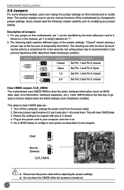
... used to enable/disable the Execute Disable Bit feature. Set Limit CPUID Maximum to run multiple operating systems and applications in independent partitions or "containers." BIOS SETUP CPU Configuration Aptio Setup Utility - F-Center CPU Configuration Intel AES-NI CPU Brand Name: Genuine Intel(R) CPU @ 1.80GHz L1 Data Cache L1 Code Cache...
... used to enable/disable the Execute Disable Bit feature. Set Limit CPUID Maximum to run multiple operating systems and applications in independent partitions or "containers." BIOS SETUP CPU Configuration Aptio Setup Utility - F-Center CPU Configuration Intel AES-NI CPU Brand Name: Genuine Intel(R) CPU @ 1.80GHz L1 Data Cache L1 Code Cache...
User manual
Page 34
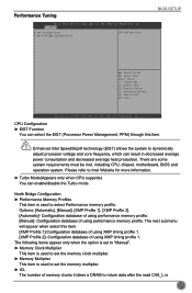
...memory profile. Copyright (C) 2011 American Megatrends, Inc. There are some system requirements must be met, including CPU, chipset, motherboard, BIOS and operation system. The next submenu will appear when select this item. C opyright (C) 2011 American Megatrends, Inc. N CAUTIO ...Bridge Configuration ► Performance Memory Profiles This item is 27 F-Center ▶ CPU Configuration ▶ North Bridge Configuration CPU Configuration BIOS SETUP → ←: Select Screen ↑ ↓: Select Item Enter: Select +/-: Change Opt. Configuration database of memory ...
...memory profile. Copyright (C) 2011 American Megatrends, Inc. There are some system requirements must be met, including CPU, chipset, motherboard, BIOS and operation system. The next submenu will appear when select this item. C opyright (C) 2011 American Megatrends, Inc. N CAUTIO ...Bridge Configuration ► Performance Memory Profiles This item is 27 F-Center ▶ CPU Configuration ▶ North Bridge Configuration CPU Configuration BIOS SETUP → ←: Select Screen ↑ ↓: Select Item Enter: Select +/-: Change Opt. Configuration database of memory ...
User manual
Page 35
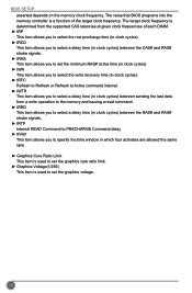
... four activates are allowed the same rank. ► Graphics Core Ratio Limit This item is used to set the graphics voltage. 28 The value that BIOS programs into the memory controller is used to set the graphics care ratio limit. ► Graphics Voltage(1/256) This item is a function of the target...
... four activates are allowed the same rank. ► Graphics Core Ratio Limit This item is used to set the graphics voltage. 28 The value that BIOS programs into the memory controller is used to set the graphics care ratio limit. ► Graphics Voltage(1/256) This item is a function of the target...

User manual
Page 36
... Save & Exit ▶ North Bridge ▶ ME Subsystem ▶ Onboard Device Configuration ▶ SATA Configuration ▶ Super IO Configuration ▶ Trusted Computing North Bridge Parameters BIOS SETUP → ←: Select Screen ↑ ↓: Select Item Enter: Select +/-: Change Opt.
... Save & Exit ▶ North Bridge ▶ ME Subsystem ▶ Onboard Device Configuration ▶ SATA Configuration ▶ Super IO Configuration ▶ Trusted Computing North Bridge Parameters BIOS SETUP → ←: Select Screen ↑ ↓: Select Item Enter: Select +/-: Change Opt.
User manual
Page 37
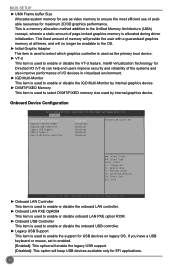
BIOS SETUP ► UMA Frame buffer Size Allocates system memory for use of page-locked graphics memory is allocated during driver initialization. This is used to ...
BIOS SETUP ► UMA Frame buffer Size Allocates system memory for use of page-locked graphics memory is allocated during driver initialization. This is used to ...

User manual
Page 38
... SATA drives must also support AHCI. ► SATA Port1/SATA Port2/SATA Port3/SATA Port4 Press to go to show the SATA Device information. 31 BIOS SETUP SATA Configuration Aptio Setup Utility - Copyright (C) 2011 American Megatrends, Inc. ► Onboard SATA Controller This item is used to enable or disable the onboard...
... SATA drives must also support AHCI. ► SATA Port1/SATA Port2/SATA Port3/SATA Port4 Press to go to show the SATA Device information. 31 BIOS SETUP SATA Configuration Aptio Setup Utility - Copyright (C) 2011 American Megatrends, Inc. ► Onboard SATA Controller This item is used to enable or disable the onboard...

User manual
Page 39
... select an optimal settings for the parallel port. F1: General Help F2: Previous Values F3: Optimized Defaults F4: Save & Exit ESC: Exit Version 2.14.1219. BIOS SETUP Super IO Configuration Aptio Setup Utility -
... select an optimal settings for the parallel port. F1: General Help F2: Previous Values F3: Optimized Defaults F4: Save & Exit ESC: Exit Version 2.14.1219. BIOS SETUP Super IO Configuration Aptio Setup Utility -


