English Manual.
Page 6
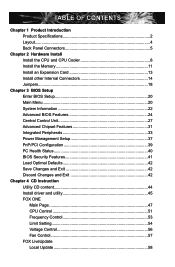
...the Memory 11 Install an Expansion Card 13 Install other Internal Connectors 14 Jumpers 18 Chapter 3 BIOS Setup Enter BIOS Setup 20 Main Menu 20 System Information 22 Advanced BIOS Features 24 Central Control Unit 27 Advanced Chipset Features 31 Integrated Peripherals 33 Power Management Setup 37... PnP/PCI Configuration 39 PC Health Status 40 BIOS Security Features 41 Load Optimal Defaults 42 Save Changes and Exit 42 Discard Changes and Exit 42 Chapter 4 CD Instruction Utility...
...the Memory 11 Install an Expansion Card 13 Install other Internal Connectors 14 Jumpers 18 Chapter 3 BIOS Setup Enter BIOS Setup 20 Main Menu 20 System Information 22 Advanced BIOS Features 24 Central Control Unit 27 Advanced Chipset Features 31 Integrated Peripherals 33 Power Management Setup 37... PnP/PCI Configuration 39 PC Health Status 40 BIOS Security Features 41 Load Optimal Defaults 42 Save Changes and Exit 42 Discard Changes and Exit 42 Chapter 4 CD Instruction Utility...
English Manual.
Page 15
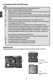
...: (Go to install the CPU : ■ Make sure that supports HT Technology and has it does not meet the standard requirements for HT Technology ■ A BIOS that the motherboard supports the CPU. ■ Always turn on the computer if the CPU cooler is optimized for the peripherals. Read the following guidelines...
...: (Go to install the CPU : ■ Make sure that supports HT Technology and has it does not meet the standard requirements for HT Technology ■ A BIOS that the motherboard supports the CPU. ■ Always turn on the computer if the CPU cooler is optimized for the peripherals. Read the following guidelines...

English Manual.
Page 18
... memory : ■ Make sure that the motherboard supports the memory. If you begin to insert the memory, switch the direction. When memory is installed, the BIOS will automatically check the memory in only one direction. Four DDR2 memory sockets are divided into two channels and each channel has two memory sockets...
... memory : ■ Make sure that the motherboard supports the memory. If you begin to insert the memory, switch the direction. When memory is installed, the BIOS will automatically check the memory in only one direction. Four DDR2 memory sockets are divided into two channels and each channel has two memory sockets...

English Manual.
Page 20
...Make sure the graphics card is fully seated in the slot. 3. Remove the metal slot cover from the slot. 13 13 If necessary, go to BIOS Setup to correctly install your expansion card in your operating system. CAUTION 2 2-3 Install an Expansion Card ! ■ Make sure the motherboard supports the ...Card: Gently insert the graphics card into the slot. 4. PCI Express x1 PCI Express x16 PCI Follow the steps below to make any required BIOS changes for your expansion card. ■ Always turn off the computer and unplug the power cord from the power outlet before installing an expansion ...
...Make sure the graphics card is fully seated in the slot. 3. Remove the metal slot cover from the slot. 13 13 If necessary, go to BIOS Setup to correctly install your expansion card in your operating system. CAUTION 2 2-3 Install an Expansion Card ! ■ Make sure the motherboard supports the ...Card: Gently insert the graphics card into the slot. 4. PCI Express x1 PCI Express x16 PCI Follow the steps below to make any required BIOS changes for your expansion card. ■ Always turn off the computer and unplug the power cord from the power outlet before installing an expansion ...

English Manual.
Page 24
... transfer rate. 1 GND TX+ TXGND RXRX+ GND SATA_1/2/3/4/5/6 Fan Connectors : CPU_FAN, SYS_FAN, NB_FAN There are three main fan headers on this feature. 2 1394a Connector : F_1394 (P45AL-S) The 1394a expansion cable can be automatically turned off after the system enters S3, S4 and S5 sleeping states. 1 GND POWER SENSE CONTROL CPU_FAN/ SYS_FAN... Disk or CD devices which support this motherboard. The fan speed can be connected to connect with the appropriate interface) or real panel of the BIOS Setup.
... transfer rate. 1 GND TX+ TXGND RXRX+ GND SATA_1/2/3/4/5/6 Fan Connectors : CPU_FAN, SYS_FAN, NB_FAN There are three main fan headers on this feature. 2 1394a Connector : F_1394 (P45AL-S) The 1394a expansion cable can be automatically turned off after the system enters S3, S4 and S5 sleeping states. 1 GND POWER SENSE CONTROL CPU_FAN/ SYS_FAN... Disk or CD devices which support this motherboard. The fan speed can be connected to connect with the appropriate interface) or real panel of the BIOS Setup.
English Manual.
Page 25
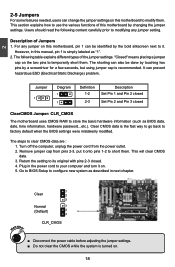
...use the various functions of this motherboard, pin 1 can also be identified by changing the jumper settings. The steps to factory default when the BIOS settings were mistakenly modified. This will clear CMOS data. 3. 2 2-5 Jumpers For some features needed, users can prevent hazardous ESD (Electrical ...2-3, put it on this manual, pin 1 is recommended. Plug in this motherboard to configure new system as BIOS data, date, time information, hardware password...etc.). Go to BIOS Setup to modify them. The shorting can be done by touching two pins by a screwdriver for a few ...
...use the various functions of this motherboard, pin 1 can also be identified by changing the jumper settings. The steps to factory default when the BIOS settings were mistakenly modified. This will clear CMOS data. 3. 2 2-5 Jumpers For some features needed, users can prevent hazardous ESD (Electrical ...2-3, put it on this manual, pin 1 is recommended. Plug in this motherboard to configure new system as BIOS data, date, time information, hardware password...etc.). Go to BIOS Setup to modify them. The shorting can be done by touching two pins by a screwdriver for a few ...

English Manual.
Page 26
...chapter tells how to change the default CMOS settings. You have to change system settings through the BIOS Setup menus. We do not guarantee the content of the BIOS parameters are also provided. Please visit our website for reference only. You want to run the ...Setup Program when the following information : ■ Enter BIOS Setup ■ Main Menu ■ System Information ■ Advanced BIOS Features ■ Central Control Unit ■ Advanced Chipset Features ■ Integrated Peripherals ■ Power Management Setup ...
...chapter tells how to change the default CMOS settings. You have to change system settings through the BIOS Setup menus. We do not guarantee the content of the BIOS parameters are also provided. Please visit our website for reference only. You want to run the ...Setup Program when the following information : ■ Enter BIOS Setup ■ Main Menu ■ System Information ■ Advanced BIOS Features ■ Central Control Unit ■ Advanced Chipset Features ■ Integrated Peripherals ■ Power Management Setup ...
English Manual.
Page 27
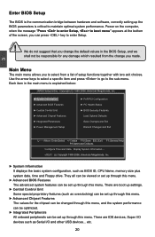
...together with two exit choices. Power on the computer, when the message "Press to enter Setup, to enter Setup. ! 3 CAUTION Enter BIOS Setup The BIOS is the communication bridge between hardware and software, correctly setting up through this menu. They all can be viewed or set up through this... menu. ► Advanced BIOS Features The advanced system features can be set up through this menu. ► Advanced Chipset Features The values for the chipset can be ...
...together with two exit choices. Power on the computer, when the message "Press to enter Setup, to enter Setup. ! 3 CAUTION Enter BIOS Setup The BIOS is the communication bridge between hardware and software, correctly setting up through this menu. They all can be viewed or set up through this... menu. ► Advanced BIOS Features The advanced system features can be set up through this menu. ► Advanced Chipset Features The values for the chipset can be ...

English Manual.
Page 28
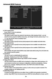
... you have more memory or I/O cards installed. It means, if your system loading is to adjust BIOS setting one by one, trial and error, to find out the best setting for your CPU/System. ► BIOS Security Features The Supervisor/User password can be modified through this option. ► PC Health Status...
... you have more memory or I/O cards installed. It means, if your system loading is to adjust BIOS setting one by one, trial and error, to find out the best setting for your CPU/System. ► BIOS Security Features The Supervisor/User password can be modified through this option. ► PC Health Status...
English Manual.
Page 29
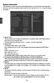
... the value. ► Primary/Secondary/Fifth/Sixth IDE Master/Slave, Third/Fourth IDE Master While entering setup, BIOS automatically detects the presence of the Floppy Disk Drive is detected during powering up by BIOS (Read Only). Use [Enter], [Tab] or [Shift-Tab] to configure the desired time. Use [+] ... setting. This item displays the drive information of the setting are : : respectively. ► System Date format. Use the arrow up the standard BIOS features, such as the date, time, floppy drive and so on. Year-year, set up /down keys to select an item, then use the...
... the value. ► Primary/Secondary/Fifth/Sixth IDE Master/Slave, Third/Fourth IDE Master While entering setup, BIOS automatically detects the presence of the Floppy Disk Drive is detected during powering up by BIOS (Read Only). Use [Enter], [Tab] or [Shift-Tab] to configure the desired time. Use [+] ... setting. This item displays the drive information of the setting are : : respectively. ► System Date format. Use the arrow up the standard BIOS features, such as the date, time, floppy drive and so on. Year-year, set up /down keys to select an item, then use the...
English Manual.
Page 30
...- - ESATA - ESATA - ESATA - SATA 1 SATA 1 SATA 3 SATA 3 SATA 2 SATA 2 SATA 4 SATA 4 SATA 5 ESATA - - User can check this product. ► BIOS Version It displays the current BIOS version. ESATA - ESATA - Not Used - - - - SATA 6 - - - SATA 6 - IDE0 IDE1 - - - - - - - 23 The size is needed. ► ...this item. ► Model Name Model name of this information and discuss with the field service people if a BIOS upgrade is depending on how many memory modules were installed in your system before powering on. ► MAC ...
...- - ESATA - ESATA - ESATA - SATA 1 SATA 1 SATA 3 SATA 3 SATA 2 SATA 2 SATA 4 SATA 4 SATA 5 ESATA - - User can check this product. ► BIOS Version It displays the current BIOS version. ESATA - ESATA - Not Used - - - - SATA 6 - - - SATA 6 - IDE0 IDE1 - - - - - - - 23 The size is needed. ► ...this item. ► Model Name Model name of this information and discuss with the field service people if a BIOS upgrade is depending on how many memory modules were installed in your system before powering on. ► MAC ...
English Manual.
Page 31
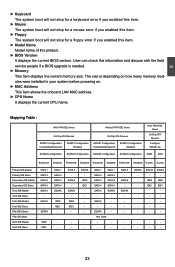
... will not detect the floppy. ► Bootup Num-Lock This item defines if the keyboard Num Lock key is active when your BIOS from being affected by pressing . ► Hard Disk Drives This option is used to specify the boot priority sequence from available hard... ► Boot Device Priority ► Hard Disk Drives ► Removable Drives ► CD/DVD Drives Quick Boot Quiet Boot Floppy Drive Seek Bootup Num-Lock BIOS Write Protect [Press Enter] Help Item [Press Enter] [Press Enter] Configure CPU. [Press Enter] [Press Enter] [Enabled] [Enabled] [Disabled] [On] ...
... will not detect the floppy. ► Bootup Num-Lock This item defines if the keyboard Num Lock key is active when your BIOS from being affected by pressing . ► Hard Disk Drives This option is used to specify the boot priority sequence from available hard... ► Boot Device Priority ► Hard Disk Drives ► Removable Drives ► CD/DVD Drives Quick Boot Quiet Boot Floppy Drive Seek Bootup Num-Lock BIOS Write Protect [Press Enter] Help Item [Press Enter] [Press Enter] Configure CPU. [Press Enter] [Press Enter] [Enabled] [Enabled] [Disabled] [On] ...
English Manual.
Page 33
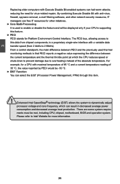
..., PPM) through this feature. ► PECI PECI stands for Platform Environment Control Interface. There are some system requirements must be met, including CPU, chipset, motherboard, BIOS and operation system. The PECI bus, allowing access to this data from 2 kbit/s to 2 Mbit/s). From a control standpoint, the main difference between the current temperature...
..., PPM) through this feature. ► PECI PECI stands for Platform Environment Control Interface. There are some system requirements must be met, including CPU, chipset, motherboard, BIOS and operation system. The PECI bus, allowing access to this data from 2 kbit/s to 2 Mbit/s). From a control standpoint, the main difference between the current temperature...

English Manual.
Page 36
... remember the current CPU clock value on the screen before your PC restarts ) in your overclock system. 29 Select [OK], and press [Enter], then BIOS will restart itself . 3 ► Run Setup Over Clock This setting is reached, system will increase CPU clock step by step, drive the system to... and a message displays : System recovers from Setup Over Clock Press F1 to Resume You can then press [F1] to continue, press [Del] to enter BIOS again, and select "O.C. Configuration" menu, enter an appropriate CPU clock value (smaller than the latest CPU clock value shown on the screen.
... remember the current CPU clock value on the screen before your PC restarts ) in your overclock system. 29 Select [OK], and press [Enter], then BIOS will restart itself . 3 ► Run Setup Over Clock This setting is reached, system will increase CPU clock step by step, drive the system to... and a message displays : System recovers from Setup Over Clock Press F1 to Resume You can then press [F1] to continue, press [Del] to enter BIOS again, and select "O.C. Configuration" menu, enter an appropriate CPU clock value (smaller than the latest CPU clock value shown on the screen.
English Manual.
Page 37
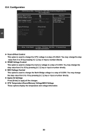
... voltage in a step of 6.25mV. Configuration CMOS Setup Utility - Configuration VCore Offset Control [0] Help Item VRAM Voltage Control [3] DRAM Approx Voltage: 1.758V+0.048Vx3=1.902V Allows BIOS to change the step value from 0 to 30 by pressing [+] / [-] key or input a number directly. ► Apply All Settings Press [Enter] to apply all the...
... voltage in a step of 6.25mV. Configuration CMOS Setup Utility - Configuration VCore Offset Control [0] Help Item VRAM Voltage Control [3] DRAM Approx Voltage: 1.758V+0.048Vx3=1.902V Allows BIOS to change the step value from 0 to 30 by pressing [+] / [-] key or input a number directly. ► Apply All Settings Press [Enter] to apply all the...
English Manual.
Page 39
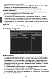
Once this option is enabled, the BIOS can select a value manually such as [667 MHz] or [800 MHz]. ► Memory Timing by SPD device. You also can see maximum 8192 MB of ...
Once this option is enabled, the BIOS can select a value manually such as [667 MHz] or [800 MHz]. ► Memory Timing by SPD device. You also can see maximum 8192 MB of ...
English Manual.
Page 42
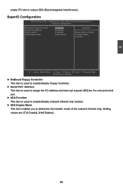
... determine the transfer mode of the onboard infrared chip. SuperIO Configuration OnBoard Floppy Controller [Enabled] Help Item Serial Port Address [Enabled] IrDA Function [Enabled] Allows BIOS to Enable IrDA Duplex Mode [Half Duplex] or disable floppy controller.
... determine the transfer mode of the onboard infrared chip. SuperIO Configuration OnBoard Floppy Controller [Enabled] Help Item Serial Port Address [Enabled] IrDA Function [Enabled] Allows BIOS to Enable IrDA Duplex Mode [Half Duplex] or disable floppy controller.
English Manual.
Page 43
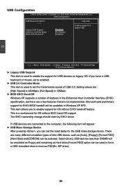
...enable support for legacy USB. Select [Auto], USB devices less than 530MB will be selected. Microsoft said preliminary support for EHCI BIOS handoff will be emulated as Floppy and remaining as hard drive.[Forced FDD] option can be available in the Enhanced Host Controller ...USB 2.0. There are not implemented. 3 USB Configuration CMOS Setup Utility - Legacy USB Support [Enabled] USB 2.0 Controller Mode [Full Speed] BIOS EHCI Hand-Off [Enabled] Move Enter:Select +/-/:Value F10:Save ESC:Exit F1:General Help F9:Optimized Defaults ► Legacy USB Support ...
...enable support for legacy USB. Select [Auto], USB devices less than 530MB will be selected. Microsoft said preliminary support for EHCI BIOS handoff will be emulated as Floppy and remaining as hard drive.[Forced FDD] option can be available in the Enhanced Host Controller ...USB 2.0. There are not implemented. 3 USB Configuration CMOS Setup Utility - Legacy USB Support [Enabled] USB 2.0 Controller Mode [Full Speed] BIOS EHCI Hand-Off [Enabled] Move Enter:Select +/-/:Value F10:Save ESC:Exit F1:General Help F9:Optimized Defaults ► Legacy USB Support ...

English Manual.
Page 44
... a period of mobile, desktop, and server platforms. It defines five sleeping states, they are lost (the OS is responsible for initial boot operations within the BIOS to distinguish whether or not the boot is going to a minimum, it is a low wake latency sleeping state where all devices. The S3 sleeping state...
... a period of mobile, desktop, and server platforms. It defines five sleeping states, they are lost (the OS is responsible for initial boot operations within the BIOS to distinguish whether or not the boot is going to a minimum, it is a low wake latency sleeping state where all devices. The S3 sleeping state...
English Manual.
Page 46
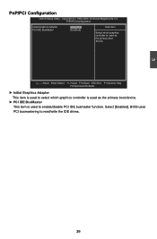
... controller is used as the primary boot device. ► PCI IDE BusMaster This item is used to read/write the IDE drives. 39 Select [Enabled], BIOS uses PCI busmastering to enable/disable PCI IDE busmaster function.
... controller is used as the primary boot device. ► PCI IDE BusMaster This item is used to read/write the IDE drives. 39 Select [Enabled], BIOS uses PCI busmastering to enable/disable PCI IDE busmaster function.


