
Specifications
Page 1
C141-C010-01EN MAW3073, MAW3147, MAW3300 NP/NC SERIES MAX3036, MAX3073, MAX3147 NP/NC SERIES DISK DRIVES SCSI LOGICAL INTERFACE SPECIFICATIONS
C141-C010-01EN MAW3073, MAW3147, MAW3300 NP/NC SERIES MAX3036, MAX3073, MAX3147 NP/NC SERIES DISK DRIVES SCSI LOGICAL INTERFACE SPECIFICATIONS

Specifications
Page 5
.../NC, MAX3073NP/NC, MAX3147NP/NC series 3.5 inch hard disk drives with this manual are shown in the disk drives. C141-C010 i Chapter 3 Command Specifications This chapter describes specifications of SCSI commands provided by the disk drives and how to use these magnetic disk drives incorporated into user systems, and to SCSI command processing in "Manual Organization," provided on a subsequent...
.../NC, MAX3073NP/NC, MAX3147NP/NC series 3.5 inch hard disk drives with this manual are shown in the disk drives. C141-C010 i Chapter 3 Command Specifications This chapter describes specifications of SCSI commands provided by the disk drives and how to use these magnetic disk drives incorporated into user systems, and to SCSI command processing in "Manual Organization," provided on a subsequent...
Specifications
Page 8
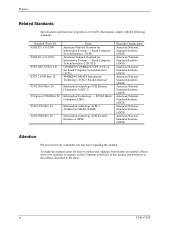
... easier for users to the address described in the sheet. Small Computer System Interface (SCSI) American National Standard for Information Systems --- Small Computer System Interface-2 (SCSI-2) COMMON COMMAND SET (CCS) of this manual comply with the following standards. Please...of the Small Computer System Interface (SCSI) WORKING DRAFT Information Technology SCSI-3 Parallel Interface T10/1236-D Rev 20 Information technology SCSI Primary Commands-2 (SPC-2) T10 project 996D Rev 8C Information Technology --- Preface Related Standards Specifications and functions of products covered by ...
... easier for users to the address described in the sheet. Small Computer System Interface (SCSI) American National Standard for Information Systems --- Small Computer System Interface-2 (SCSI-2) COMMON COMMAND SET (CCS) of this manual comply with the following standards. Please...of the Small Computer System Interface (SCSI) WORKING DRAFT Information Technology SCSI-3 Parallel Interface T10/1236-D Rev 20 Information technology SCSI Primary Commands-2 (SPC-2) T10 project 996D Rev 8C Information Technology --- Preface Related Standards Specifications and functions of products covered by ...

Specifications
Page 9
Command Specifications 4. Data Format 4. SCSI Bus 2. MANUAL ORGANIZATION Product/ Maintenance Manual (C141-E234/C141-E235) SCSI Physical Interface Specifications (C141-C011) SCSI Logical Interface Specifications (C141-C010) (This Manual) 1. Installation Requirements 5. Command Processing 2. Parameter Data Formats 5. Diagnostics and Maintenance 7. Error Analysis 1. Data Buffer Management 3. Disk Media Management C141-C010 v Error Recovery 1. Sense Data Error Recovery Methods 6. SCSI Message 3. General Description 2. Installation 6. Specifications 3.
Command Specifications 4. Data Format 4. SCSI Bus 2. MANUAL ORGANIZATION Product/ Maintenance Manual (C141-E234/C141-E235) SCSI Physical Interface Specifications (C141-C011) SCSI Logical Interface Specifications (C141-C010) (This Manual) 1. Installation Requirements 5. Command Processing 2. Parameter Data Formats 5. Diagnostics and Maintenance 7. Error Analysis 1. Data Buffer Management 3. Disk Media Management C141-C010 v Error Recovery 1. Sense Data Error Recovery Methods 6. SCSI Message 3. General Description 2. Installation 6. Specifications 3.

Specifications
Page 11
... ...1-22 1.6.1 Sense data hold condition...1-22 1.6.2 Response and release conditions at sense data hold state 1-22 1.7 Command Processing Exceptions...1-23 1.7.1 Overlapping commands...1-23 1.7.2 Illegal LUN specification ...1-24 1.7.3 Reserved operation code...1-24 1.7.4 Command processing in the not ready state 1-24 1.7.5 Error recovery processing ...1-26 1.7.6 Reset processing ...1-28 1.7.7 Fatal hardware errors...1-29 1.8 Data...
... ...1-22 1.6.1 Sense data hold condition...1-22 1.6.2 Response and release conditions at sense data hold state 1-22 1.7 Command Processing Exceptions...1-23 1.7.1 Overlapping commands...1-23 1.7.2 Illegal LUN specification ...1-24 1.7.3 Reserved operation code...1-24 1.7.4 Command processing in the not ready state 1-24 1.7.5 Error recovery processing ...1-26 1.7.6 Reset processing ...1-28 1.7.7 Fatal hardware errors...1-29 1.8 Data...

Specifications
Page 12
Contents 2.1.2 Operation mode setting...2-5 2.2 Look-Ahead Cache Feature ...2-6 2.2.1 Caching operation...2-6 2.2.2 Caching parameters ...2-9 2.2.3 Look-Ahead operation, Look-Ahead volume 2-10 2.3 Write Cache ...2-11 CHAPTER 3 Command Specifications ...3-1 3.1 Control/Sense Commands...3-1 3.1.1 TEST UNIT READY (00)...3-1 3.1.2 INQUIRY (12)...3-2 3.1.3 READ CAPACITY (25)...3-13 3.1.4 CHANGE DEFINITION (40) ...3-14 3.1.5 MODE SELECT (15) ...3-19 3.1.6 MODE SELECT EXTENDED (55 3-...
Contents 2.1.2 Operation mode setting...2-5 2.2 Look-Ahead Cache Feature ...2-6 2.2.1 Caching operation...2-6 2.2.2 Caching parameters ...2-9 2.2.3 Look-Ahead operation, Look-Ahead volume 2-10 2.3 Write Cache ...2-11 CHAPTER 3 Command Specifications ...3-1 3.1 Control/Sense Commands...3-1 3.1.1 TEST UNIT READY (00)...3-1 3.1.2 INQUIRY (12)...3-2 3.1.3 READ CAPACITY (25)...3-13 3.1.4 CHANGE DEFINITION (40) ...3-14 3.1.5 MODE SELECT (15) ...3-19 3.1.6 MODE SELECT EXTENDED (55 3-...

Specifications
Page 17
... status 5-13 Tables Table 1.1 Table 1.2 Table 1.3 Table 1.4 Table 1.5 Table 1.6 Responses to Link Specification Commands 1-10 Types of Command and Disconnect Processing 1-12 Sense data in not ready state...1-25 Outline of SCSI Bus Error Recovery Processing 1-27 Outline of disk drive error recovery processing 1-27 Reset processing during write...1-29 Table 3.1 Table 3.2 Table...
... status 5-13 Tables Table 1.1 Table 1.2 Table 1.3 Table 1.4 Table 1.5 Table 1.6 Responses to Link Specification Commands 1-10 Types of Command and Disconnect Processing 1-12 Sense data in not ready state...1-25 Outline of SCSI Bus Error Recovery Processing 1-27 Outline of disk drive error recovery processing 1-27 Reset processing during write...1-29 Table 3.1 Table 3.2 Table...

Specifications
Page 19
.... The CDB is mentioned as the target (TARG) on the SCSI bus. In a number of commands, the parameters which are accomplished by the IDD has 3 formats, these are described in the specifications for command execution in the DATA OUT phase may be specified in... Function 1.5 UNIT ATTENTION Condition 1.6 Sense Data Hold State 1.7 Command Processing Exceptions 1.8 Data Block Addressing This chapter describes the basic logical specifications of each individual command in Chapter 3. In the explanations in this chapter, the IDD is information transferred from INIT (initiator) to TARG...
.... The CDB is mentioned as the target (TARG) on the SCSI bus. In a number of commands, the parameters which are accomplished by the IDD has 3 formats, these are described in the specifications for command execution in the DATA OUT phase may be specified in... Function 1.5 UNIT ATTENTION Condition 1.6 Sense Data Hold State 1.7 Command Processing Exceptions 1.8 Data Block Addressing This chapter describes the basic logical specifications of each individual command in Chapter 3. In the explanations in this chapter, the IDD is information transferred from INIT (initiator) to TARG...

Specifications
Page 20
Depending on the type of command, the basic format of the CDB, the definitions of the fields in the CDB are described in the specifications for each of fields and their meanings may differ. Command Processing Bit Byte 7 6 5 4 3 2 1 0 0 Operation Code 1 LUN 0 0 0 0 0 2 Logical Block Address (MSB) 3 Logical Block Address 4 Logical Block ...
Depending on the type of command, the basic format of the CDB, the definitions of the fields in the CDB are described in the specifications for each of fields and their meanings may differ. Command Processing Bit Byte 7 6 5 4 3 2 1 0 0 Operation Code 1 LUN 0 0 0 0 0 2 Logical Block Address (MSB) 3 Logical Block Address 4 Logical Block ...

Specifications
Page 21
... is possible that a zero be specified in this field may be executed. In the group 0 CDB, 21-bit block addressing is possible and in future SCSI standards. a. It is specified. 1.1 Command Format (1) Operation code Bit 7 6 5 4 3 2 1 0 Group Code Command Code The leading byte of all ...(2) LUN (Logical Unit Number) This field specifies the address of the logical unit (device) connected under the TARG in Section 1.7.3) b. Specifications for logical data block addressing in the IDD are used . Group code The group code specifies the number of bytes and format of the ...
... is possible that a zero be specified in this field may be executed. In the group 0 CDB, 21-bit block addressing is possible and in future SCSI standards. a. It is specified. 1.1 Command Format (1) Operation code Bit 7 6 5 4 3 2 1 0 Group Code Command Code The leading byte of all ...(2) LUN (Logical Unit Number) This field specifies the address of the logical unit (device) connected under the TARG in Section 1.7.3) b. Specifications for logical data block addressing in the IDD are used . Group code The group code specifies the number of bytes and format of the ...

Specifications
Page 22
... length of data to the IDD, this field, data transfer is not executed, except in cases where it is expressly stated in the individual command specifications in length, if the field's specified value is 0, no data transfer is regarded as the transfer data length field. Detailed... commands where this field is sending. It is possible to specify a block count ranging from 0 to 256 blocks. There are described in the individual command specifications in the "Transfer Byte Length" field, whichever is specified by the number of logical data blocks or the number of bytes.
... length of data to the IDD, this field, data transfer is not executed, except in cases where it is expressly stated in the individual command specifications in length, if the field's specified value is 0, no data transfer is regarded as the transfer data length field. Detailed... commands where this field is sending. It is possible to specify a block count ranging from 0 to 256 blocks. There are described in the individual command specifications in the "Transfer Byte Length" field, whichever is specified by the number of logical data blocks or the number of bytes.

Specifications
Page 23
...in the parameters transferred in the DATA OUT phase, the contents of a command to the disk media. If there is an error in the CDB specification in a command which executes disconnect processing (shown in the range specified by that has been received, the status (CHECK CONDITION) is terminated. Note:... these bits, the command ends with a CHECK CONDITION status. Also, even in cases where there is an error in the CDB's specifications in the CDB's specifications, the disk media is "1." Link Command link is terminated, but those data are not written to change the data on the disk ...
...in the parameters transferred in the DATA OUT phase, the contents of a command to the disk media. If there is an error in the CDB specification in a command which executes disconnect processing (shown in the range specified by that has been received, the status (CHECK CONDITION) is terminated. Note:... these bits, the command ends with a CHECK CONDITION status. Also, even in cases where there is an error in the CDB's specifications in the CDB's specifications, the disk media is "1." Link Command link is terminated, but those data are not written to change the data on the disk ...

Specifications
Page 27
... in the Link bit of its CDB is issued or until a command terminates abnormally. The command link continues until a command with a Link specification are completed normally. At this time, the command link function becomes effective. 6) The TARG informs the INIT of multiple commands. 1.3 Outline of... of the CDB by the group code in the command pointer, data pointer and status pointer. 2) Obtaining the SCSI bus usage, selection of the TARG and specification of single command. 3) The TARG receives commands from the INIT. Following shows examples of command link processing. 1)...
... in the Link bit of its CDB is issued or until a command terminates abnormally. The command link continues until a command with a Link specification are completed normally. At this time, the command link function becomes effective. 6) The TARG informs the INIT of multiple commands. 1.3 Outline of... of the CDB by the group code in the command pointer, data pointer and status pointer. 2) Obtaining the SCSI bus usage, selection of the TARG and specification of single command. 3) The TARG receives commands from the INIT. Following shows examples of command link processing. 1)...

Specifications
Page 28
... INIT which uses the command link function must make the ATN signal in CDB [=24-00]). 1-10 C141-C010 Command Processing Table 1.1 Responses to Link Specification Commands End Status Status Completed Normally INTERMEDIATE Completed Abnormally CHECK CONDITION Conditions Met INTERMEDIATE CONDITION MET Unable to Start Receive BUSY Reserved State RESERVATION CONFLICT...
... INIT which uses the command link function must make the ATN signal in CDB [=24-00]). 1-10 C141-C010 Command Processing Table 1.1 Responses to Link Specification Commands End Status Status Completed Normally INTERMEDIATE Completed Abnormally CHECK CONDITION Conditions Met INTERMEDIATE CONDITION MET Unable to Start Receive BUSY Reserved State RESERVATION CONFLICT...

Specifications
Page 30
... processing: In cases only where commands are issued without a tag, queuing processing (see Section 1.4) and disconnect processing cannot be executed depending on the processing content specification of Command and Disconnect Processing Commands with executing disconnect processing: Regardless of command queuing, in the execution sequence.
... processing: In cases only where commands are issued without a tag, queuing processing (see Section 1.4) and disconnect processing cannot be executed depending on the processing content specification of Command and Disconnect Processing Commands with executing disconnect processing: Regardless of command queuing, in the execution sequence.

Specifications
Page 31
... of the last data is completed. In this time, if necessary, the IDD sends a message to activate a pointer in "SCSI Physical Interface Specifications" and "Chapter 2 SCSI Messages." 2) After the IDD enters the BUS FREE phase, it is possible for it to disconnect from the... SCSI bus during execution of a command, it possible to the SCSI pointer description in the INIT which performs disconnect processing internally. 4) After that , the IDD...
... of the last data is completed. In this time, if necessary, the IDD sends a message to activate a pointer in "SCSI Physical Interface Specifications" and "Chapter 2 SCSI Messages." 2) After the IDD enters the BUS FREE phase, it is possible for it to disconnect from the... SCSI bus during execution of a command, it possible to the SCSI pointer description in the INIT which performs disconnect processing internally. 4) After that , the IDD...

Specifications
Page 33
...details, refer to CHANGE DEFINITION parameter list (Reselection Retry, Reselection Time-out Delay) in Section 3.1.4 and SCSI Bus (RESELECTION phase) in Chapter 1 of "SCSI Physical Interface Specifications" and SCSI Bus Error Recovery Processing in order for the INIT to avoid overhead time for message exchange, the INIT ... necessary for executing the synchronous mode transfer. 1.3 Outline of Command Processing 3) After the INIT that the asynchronous mode is set the SCSI bus width in 8 bit widths or 16 bit widths (wide mode), but by using synchronous mode data transfer or wide mode data...
...details, refer to CHANGE DEFINITION parameter list (Reselection Retry, Reselection Time-out Delay) in Section 3.1.4 and SCSI Bus (RESELECTION phase) in Chapter 1 of "SCSI Physical Interface Specifications" and SCSI Bus Error Recovery Processing in order for the INIT to avoid overhead time for message exchange, the INIT ... necessary for executing the synchronous mode transfer. 1.3 Outline of Command Processing 3) After the INIT that the asynchronous mode is set the SCSI bus width in 8 bit widths or 16 bit widths (wide mode), but by using synchronous mode data transfer or wide mode data...

Specifications
Page 34
.... Command Processing The IDD maintains data transfer mode settings between itself and each INIT. Also, the parameters for synchronous mode transfers decided by the specification of "SCSI Physical Interface Specifications" for setting necessary parameters again. In such case, when requesting synchronous mode/wide mode transfer is issued every time. See "CHANGE DEFINITION" in...
.... Command Processing The IDD maintains data transfer mode settings between itself and each INIT. Also, the parameters for synchronous mode transfers decided by the specification of "SCSI Physical Interface Specifications" for setting necessary parameters again. In such case, when requesting synchronous mode/wide mode transfer is issued every time. See "CHANGE DEFINITION" in...

Specifications
Page 37
... condition is released. If '0000', '0001' is in the QErr bit, if the IDD enters any commands received from the INIT that set . See "SCSI Physical Interface Specifications" for details of the mode select parameters. If "10" is specified in the QErr bit, the IDD enters any one of a number of sense...
... condition is released. If '0000', '0001' is in the QErr bit, if the IDD enters any commands received from the INIT that set . See "SCSI Physical Interface Specifications" for details of the mode select parameters. If "10" is specified in the QErr bit, the IDD enters any one of a number of sense...

Specifications
Page 39
...; Spindle synchronized • Spindle not synchronized • Microcode has been changed • Reservations Preempted • Reservations Released • Registrations Preempted • Commands cleared by the specification of the CHANGE DEFINITION command.
...; Spindle synchronized • Spindle not synchronized • Microcode has been changed • Reservations Preempted • Reservations Released • Registrations Preempted • Commands cleared by the specification of the CHANGE DEFINITION command.
