
Maintenance Manual
Page 5
... the disk drives. CHAPTER 5 Interface This chapter describes the interface specifications of the disk drive. C141-E293 i CHAPTER 3 Installation Conditions This chapter describes the external dimensions, installation conditions, and switch settings of the disk drive. Preface This manual describes MJA2500BH, MJA2400BH, MJA2320BH, MJA2250BH, MJA2160BH, MJA2120BH, MJA2080BH model of the systems in which they operate. CHAPTER 2 Device Configuration This chapter describes the internal configurations of the disk drive and the configuration of the MJA Series, 2.5-inch hard disk drives...
... the disk drives. CHAPTER 5 Interface This chapter describes the interface specifications of the disk drive. C141-E293 i CHAPTER 3 Installation Conditions This chapter describes the external dimensions, installation conditions, and switch settings of the disk drive. Preface This manual describes MJA2500BH, MJA2400BH, MJA2320BH, MJA2250BH, MJA2160BH, MJA2120BH, MJA2080BH model of the systems in which they operate. CHAPTER 2 Device Configuration This chapter describes the internal configurations of the disk drive and the configuration of the MJA Series, 2.5-inch hard disk drives...
Maintenance Manual
Page 27
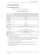
... 6.4 of this manual. *6: The value of Depth (=100.0 mm) does not include PCBA (Printed Circuit Board Assembly). Refer to 1,048,576 bytes; the actual buffer capacity for data transfer will be less. Table 1.1 Specifications (1/2) MJA2500BH MJA2400BH MJA2320BH MJA2250BH MJA2160BH MJA2120BH MJA2080BH Format Capacity (*1, *2) 500 GB 400 GB 320 GB 250 GB 160 GB 120 GB 80 GB Number of the disk drives. C141-E293 1-5 1.2 Device Specifications 1.2 Device Specifications 1.2.1 Specifications summary Table 1.1 shows the specifications of Sectors (User) 976...
... 6.4 of this manual. *6: The value of Depth (=100.0 mm) does not include PCBA (Printed Circuit Board Assembly). Refer to 1,048,576 bytes; the actual buffer capacity for data transfer will be less. Table 1.1 Specifications (1/2) MJA2500BH MJA2400BH MJA2320BH MJA2250BH MJA2160BH MJA2120BH MJA2080BH Format Capacity (*1, *2) 500 GB 400 GB 320 GB 250 GB 160 GB 120 GB 80 GB Number of the disk drives. C141-E293 1-5 1.2 Device Specifications 1.2 Device Specifications 1.2.1 Specifications summary Table 1.1 shows the specifications of Sectors (User) 976...

Maintenance Manual
Page 28
... selected using the BIOS setup utility on the operating environment and formatting. 1.2.2 Model and product number Table 1.2 lists the model names and product numbers of the disk drive. accessible capacity will be less and actual capacity depends on the operating environment and formatting. *2: Serial ATA Generation-1 (1.5 Gbps) is ordered as a replacement drive, the product number must be the same as listed in Table 1.2 since some models have been customized and have specifications that of the drive being replaced. of Sectors 8.45 GB...
... selected using the BIOS setup utility on the operating environment and formatting. 1.2.2 Model and product number Table 1.2 lists the model names and product numbers of the disk drive. accessible capacity will be less and actual capacity depends on the operating environment and formatting. *2: Serial ATA Generation-1 (1.5 Gbps) is ordered as a replacement drive, the product number must be the same as listed in Table 1.2 since some models have been customized and have specifications that of the drive being replaced. of Sectors 8.45 GB...

Maintenance Manual
Page 34
... with MTBF. (4) Data assurance in the event of power failure Except for five years when the DE surface temperature is less than 48 °C. Refer to defects that involve repair, readjustment, or replacement. Disk drive defects do not include failures caused by external factors, such as damage caused by handling, inappropriate operating environments, defects in the power supply host system, or interface cable. (2) Mean time to repair (MTTR...
... with MTBF. (4) Data assurance in the event of power failure Except for five years when the DE surface temperature is less than 48 °C. Refer to defects that involve repair, readjustment, or replacement. Disk drive defects do not include failures caused by external factors, such as damage caused by handling, inappropriate operating environments, defects in the power supply host system, or interface cable. (2) Mean time to repair (MTTR...

Maintenance Manual
Page 43
... System Configuration 2.2.1 SATA interface Figure 2.2 shows the SATA interface system configuration. 2.2 System Configuration (5) Air circulation system The disk enclosure (DE) is sealed to maintain the cleanliness of the rotating disk. It improves data reliability by preventing errors caused by external noise. (7) Controller circuit The controller circuit supports Serial-ATA interface, and it realized a high performance by each model). 2.2.2 Drive connection Operating System Application 1 Application 2 Driver Application 3 Serial ATA Adapter Disk Drive Disk Drive Figure 2.2 Drive...
... System Configuration 2.2.1 SATA interface Figure 2.2 shows the SATA interface system configuration. 2.2 System Configuration (5) Air circulation system The disk enclosure (DE) is sealed to maintain the cleanliness of the rotating disk. It improves data reliability by preventing errors caused by external noise. (7) Controller circuit The controller circuit supports Serial-ATA interface, and it realized a high performance by each model). 2.2.2 Drive connection Operating System Application 1 Application 2 Driver Application 3 Serial ATA Adapter Disk Drive Disk Drive Figure 2.2 Drive...
Maintenance Manual
Page 106
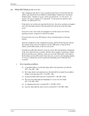
... specified in a sector, the read . If an error does not occur, PIO Setup is specified. Upon the completion of the command execution, shadow block registers contain the cylinder, head, and sector addresses (in the CHS mode) or logical block address (in the LBA mode) where the error occurred, and remaining number of sectors of which data was not transferred (including sector when the error occurred). • Error reporting conditions...
... specified in a sector, the read . If an error does not occur, PIO Setup is specified. Upon the completion of the command execution, shadow block registers contain the cylinder, head, and sector addresses (in the CHS mode) or logical block address (in the LBA mode) where the error occurred, and remaining number of sectors of which data was not transferred (including sector when the error occurred). • Error reporting conditions...

Maintenance Manual
Page 108
... Data transfer begins at the sector where the error occurred. Interface (3) WRITE SECTOR(S) (X '30' or X '31') This command writes data of sectors from 1 to 256 sectors. The data stored in the LBA mode) of the sector where the error occurred. • Error reporting conditions (1) A specified address exceeds the range where write operations are allowed (after a transfer of the R bit setting. Upon the completion of the command execution, the shadow block registers contain the cylinder, head...
... Data transfer begins at the sector where the error occurred. Interface (3) WRITE SECTOR(S) (X '30' or X '31') This command writes data of sectors from 1 to 256 sectors. The data stored in the LBA mode) of the sector where the error occurred. • Error reporting conditions (1) A specified address exceeds the range where write operations are allowed (after a transfer of the R bit setting. Upon the completion of the command execution, the shadow block registers contain the cylinder, head...
Maintenance Manual
Page 116
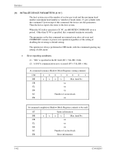
... maximum head number (maximum head number is "number of sectors/track ER Error information 5-42 C141-E293 The operation is always performed in CHS mode, with this command. head No. At command issuance (Shadow Block Registers setting contents) CM 1001000 1 DH x x x x Max. CH xx CL xx SN xx SC Number of heads minus 1") per cylinder with the command ignoring any setting of disabling the reverting to be read) ST Status information DH x x x x Max. Interface (8) INITIALIZE DEVICE PARAMETERS (X '91...
... maximum head number (maximum head number is "number of sectors/track ER Error information 5-42 C141-E293 The operation is always performed in CHS mode, with this command. head No. At command issuance (Shadow Block Registers setting contents) CM 1001000 1 DH x x x x Max. CH xx CL xx SN xx SC Number of heads minus 1") per cylinder with the command ignoring any setting of disabling the reverting to be read) ST Status information DH x x x x Max. Interface (8) INITIALIZE DEVICE PARAMETERS (X '91...
Maintenance Manual
Page 134
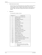
... data.) Read Error Rate Throughput Performance Spin Up Time Start/Stop Count Reallocated Sector Count Seek Error Rate Seek Time Performance Power-On Hours Count Spin Retry Count Drive Power Cycle Count Emergency Retract Cycle Count Load/Unload Cycle Count HDA Temperature ECC On the Fly Count Reallocated Event Count Current Pending Sector Count Off-Line Scan Uncorrectable Sector Count (Ultra ATA CRC Error Count) Write Error Rate Run Out Transfer Error Rate * If the device receives the reset...
... data.) Read Error Rate Throughput Performance Spin Up Time Start/Stop Count Reallocated Sector Count Seek Error Rate Seek Time Performance Power-On Hours Count Spin Retry Count Drive Power Cycle Count Emergency Retract Cycle Count Load/Unload Cycle Count HDA Temperature ECC On the Fly Count Reallocated Event Count Current Pending Sector Count Off-Line Scan Uncorrectable Sector Count (Ultra ATA CRC Error Count) Write Error Rate Run Out Transfer Error Rate * If the device receives the reset...
Maintenance Manual
Page 159
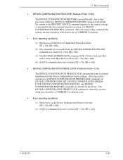
..., ER = 04h). (4) A SATA communication error occurred (ST = 51h, ER = 14h). • DEVICE CONFIGURATION FREEZE LOCK (Features Field = C1h) The DEVICE CONFIGURATION FREEZE LOCK command prevents accidental modification of a DEVICE CONFIGURATION IDENTIFY command. 5.3 Host Commands • DEVICE CONFIGURATION RESTORE (Features Field = C0h) The DEVICE CONFIGURATION RESTORE command disables any setting previously made by a DEVICE CONFIGURATION SET command and returns the content of the IDENTIFY DEVICE command response to the original settings as indicated by the data returned from the...
..., ER = 04h). (4) A SATA communication error occurred (ST = 51h, ER = 14h). • DEVICE CONFIGURATION FREEZE LOCK (Features Field = C1h) The DEVICE CONFIGURATION FREEZE LOCK command prevents accidental modification of a DEVICE CONFIGURATION IDENTIFY command. 5.3 Host Commands • DEVICE CONFIGURATION RESTORE (Features Field = C0h) The DEVICE CONFIGURATION RESTORE command disables any setting previously made by a DEVICE CONFIGURATION SET command and returns the content of the IDENTIFY DEVICE command response to the original settings as indicated by the data returned from the...

Maintenance Manual
Page 162
... IDENTIFY information "Word 76 to 0 in WORD 0 to 256 and the byte consisting of bits 7 to 79". Bits 15-5: Reserved Bit 4: 1 = Software Settings Preservation supported Bit 3: 1 = Asynchronous Notification supported Bit 2: 1 = Interface power management supported Bit 1: 1 = Non-zero buffer offsets in DMA Setup FIS supported Bit 0: 1 = Native command queuing supported X '0000' Reserved for Serial-ATA X '0000' Reserved X '2000' Bits 15-14: Reserved (X '2800' *1) Bit 13: Write...
... IDENTIFY information "Word 76 to 0 in WORD 0 to 256 and the byte consisting of bits 7 to 79". Bits 15-5: Reserved Bit 4: 1 = Software Settings Preservation supported Bit 3: 1 = Asynchronous Notification supported Bit 2: 1 = Interface power management supported Bit 1: 1 = Non-zero buffer offsets in DMA Setup FIS supported Bit 0: 1 = Native command queuing supported X '0000' Reserved for Serial-ATA X '0000' Reserved X '2000' Bits 15-14: Reserved (X '2800' *1) Bit 13: Write...

Maintenance Manual
Page 180
Interface Table 5.33 Information to be read by IDENTIFY DEVICE command (2/3) Word ...Serial ATA function *14 Major version number: ATA8-ACS *15 Minor version number: ATA8-ACS Revision 3f Support of command sets *16 Support of command sets *17 Support of command sets/function *18 Valid of command sets/function *19 Valid of command sets/function *20 Default of command sets/function *21 Ultra DMA transfer mode *22 Security Erase Unit execution time (1 LSB: 2 min.) *23 Enhanced Security Erase Unit execution time (1 LSB: 2 min.) Advance power management level Master password...
Interface Table 5.33 Information to be read by IDENTIFY DEVICE command (2/3) Word ...Serial ATA function *14 Major version number: ATA8-ACS *15 Minor version number: ATA8-ACS Revision 3f Support of command sets *16 Support of command sets *17 Support of command sets/function *18 Valid of command sets/function *19 Valid of command sets/function *20 Default of command sets/function *21 Ultra DMA transfer mode *22 Security Erase Unit execution time (1 LSB: 2 min.) *23 Enhanced Security Erase Unit execution time (1 LSB: 2 min.) Advance power management level Master password...

Maintenance Manual
Page 186
... bit LBA feature set . Bit 13: '1' = Supports the READ BUFFER command. Bit 1: '1' = Supports the Security Mode feature set . Bit 2: '1' = Supports the Removable Media feature set . Bit 0: '1' = Supports the SMART feature set . Bit 11: '1' = Supports the Device Configuration Overlay feature set . *17 WORD 83 Bit 15: 0 Bit 14: 1 Bit 13: '1' = Supports the FLUSH CACHE EXT command. Bit 7: '1' = Supports the release interrupt. Bit 12: '1' = Supports the WRITE BUFFER command. Bit 5: '1' = Supports the write cache function. Bit 7: Reserved Bit 6: '1' = When the power is...
... bit LBA feature set . Bit 13: '1' = Supports the READ BUFFER command. Bit 1: '1' = Supports the Security Mode feature set . Bit 2: '1' = Supports the Removable Media feature set . Bit 0: '1' = Supports the SMART feature set . Bit 11: '1' = Supports the Device Configuration Overlay feature set . *17 WORD 83 Bit 15: 0 Bit 14: 1 Bit 13: '1' = Supports the FLUSH CACHE EXT command. Bit 7: '1' = Supports the release interrupt. Bit 12: '1' = Supports the WRITE BUFFER command. Bit 5: '1' = Supports the write cache function. Bit 7: Reserved Bit 6: '1' = When the power is...

Maintenance Manual
Page 187
Bit 6: '1' = Support the WRITE DMA FUA EXT and WRITE MULTIPLE FUA EXT commands. Bit 8: '1' = Enables the SERVICE interrupt. Bit 4: Bit 3: Bit 2: Bit 1: Bit 0: 5.3 Host Commands '1' = Supports the Removable Media Status Notification feature set. '1' = Supports the Advanced Power Management feature set. '1' = Supports the CFA (Compact Flash Association) feature set. '1' = Supports the READ/WRITE DMA QUEUED command. '1' = Supports the DOWNLOAD MICROCODE command. *18 WORD 84 Bit 15: 0 The device always returns the fixed value indicated on the...
Bit 6: '1' = Support the WRITE DMA FUA EXT and WRITE MULTIPLE FUA EXT commands. Bit 8: '1' = Enables the SERVICE interrupt. Bit 4: Bit 3: Bit 2: Bit 1: Bit 0: 5.3 Host Commands '1' = Supports the Removable Media Status Notification feature set. '1' = Supports the Advanced Power Management feature set. '1' = Supports the CFA (Compact Flash Association) feature set. '1' = Supports the READ/WRITE DMA QUEUED command. '1' = Supports the DOWNLOAD MICROCODE command. *18 WORD 84 Bit 15: 0 The device always returns the fixed value indicated on the...

Maintenance Manual
Page 188
... the SET MAX SET PASSWORD command Bits 7-6: Same definition as WORD 83. From the SET FEATURES command '1' = Enables the write cache function. '1' = Enables the P PACKET command set. '1' = Supports the Power Management function. '1' = Supports the Removable Media function. '1' = From the SECURITY SET PASSWORD command '1' = From the SMART ENABLE OPERATION command *20 WORD 86 Bit 15: '1' = The values in WORD119-120 are valid. Bits 2-0: Same definition as WORD 84. *22 WORD 88 Bit 15-8: Currently used Ultra DMA transfer mode...
... the SET MAX SET PASSWORD command Bits 7-6: Same definition as WORD 83. From the SET FEATURES command '1' = Enables the write cache function. '1' = Enables the P PACKET command set. '1' = Supports the Power Management function. '1' = Supports the Removable Media function. '1' = From the SECURITY SET PASSWORD command '1' = From the SMART ENABLE OPERATION command *20 WORD 86 Bit 15: '1' = The values in WORD119-120 are valid. Bits 2-0: Same definition as WORD 84. *22 WORD 88 Bit 15-8: Currently used Ultra DMA transfer mode...
Maintenance Manual
Page 200
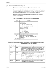
...) Master password version number (This value is valid only when Word 0 Bit 0 is turned off and then on . The lock function is enabled after the device is set . The specified password is set as a new master password. LOCKED MODE can be canceled using the user password or the master password already set as a new user password. The specified password is set as a new user password. The host transfers the 512-byte data shown in LOCKED MODE or FROZEN MODE returns the Aborted Command error. LOCKED MODE can...
...) Master password version number (This value is valid only when Word 0 Bit 0 is turned off and then on . The lock function is enabled after the device is set . The specified password is set as a new master password. LOCKED MODE can be canceled using the user password or the master password already set as a new user password. The specified password is set as a new user password. The host transfers the 512-byte data shown in LOCKED MODE or FROZEN MODE returns the Aborted Command error. LOCKED MODE can...
Maintenance Manual
Page 209
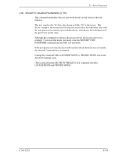
... MODE returns the Aborted Command error. (The section about the SECURITY FREEZE LOCK command describes LOCKED MODE and FROZEN MODE.) C141-E293 5-135 To recover the master password, issue the SECURITY SET PASSWORD command and reset the user password. The device compares the user password or master password in Table 5.37 to the device. If the user password or master password transferred from the host does not match, the Aborted Command error is retained. 5.3 Host Commands (34) SECURITY DISABLE PASSWORD (X 'F6') This command invalidates the user password already set...
... MODE returns the Aborted Command error. (The section about the SECURITY FREEZE LOCK command describes LOCKED MODE and FROZEN MODE.) C141-E293 5-135 To recover the master password, issue the SECURITY SET PASSWORD command and reset the user password. The device compares the user password or master password in Table 5.37 to the device. If the user password or master password transferred from the host does not match, the Aborted Command error is retained. 5.3 Host Commands (34) SECURITY DISABLE PASSWORD (X 'F6') This command invalidates the user password already set...
Maintenance Manual
Page 247
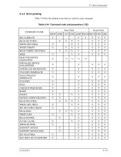
... 5.44 lists the defined errors that are valid for each command. Table 5.44 Command code and parameters (1/2) COMMAND NAME RECALIBRATE READ SECTOR(S) WRITE SECTOR(S) WRITE VERIFY READ VERIFY SECTOR(S) SEEK EXECUTE DEVICE DIAGNOSTIC INITIALIZE DEVICE PARAMETERS DOWNLOAD MICROCODE STANDBY IMMEDIATE IDLE (UNLOAD) IMMEDIATE STANDBY IDLE CHECK POWER MODE SLEEP SMART DEVICE CONFIGURATION READ MULTIPLE WRITE MULTIPLE SET MULTIPLE MODE READ DMA WRITE DMA READ BUFFER FLUSH CACHE WRITE BUFFER IDENTIFY DEVICE IDENTIFY DEVICE DMA SET FEATURES SECURITY SET PASSWORD Error Field Status Field SFRW SFRR...
... 5.44 lists the defined errors that are valid for each command. Table 5.44 Command code and parameters (1/2) COMMAND NAME RECALIBRATE READ SECTOR(S) WRITE SECTOR(S) WRITE VERIFY READ VERIFY SECTOR(S) SEEK EXECUTE DEVICE DIAGNOSTIC INITIALIZE DEVICE PARAMETERS DOWNLOAD MICROCODE STANDBY IMMEDIATE IDLE (UNLOAD) IMMEDIATE STANDBY IDLE CHECK POWER MODE SLEEP SMART DEVICE CONFIGURATION READ MULTIPLE WRITE MULTIPLE SET MULTIPLE MODE READ DMA WRITE DMA READ BUFFER FLUSH CACHE WRITE BUFFER IDENTIFY DEVICE IDENTIFY DEVICE DMA SET FEATURES SECURITY SET PASSWORD Error Field Status Field SFRW SFRR...
Maintenance Manual
Page 307
...) bit 5-25 C cache read-ahead 6-13 write 6-20 cache operation 6-20 cached data, invalidation of 6-20 caching command for 6-14, 6-20 data for 6-14 caching data, invalidating 6-15 caching operation 6-14 capability, off-line data collection 5-63 cashing function at power-on 6-21 caution, handling 3-7 CHECK POWER MODE 5-52 checksum 5-64, 5-66, 5-68 circuit controller 2-3 read/write 2-3 circuit configuration 4-3, 4-5 circulation filter 2-3 CN1 3-10 code command 5-27, 5-173 diagnostic 5-41 command code 5-27, 5-173 command code and parameter 5-27 command data structure 5-66...
...) bit 5-25 C cache read-ahead 6-13 write 6-20 cache operation 6-20 cached data, invalidation of 6-20 caching command for 6-14, 6-20 data for 6-14 caching data, invalidating 6-15 caching operation 6-14 capability, off-line data collection 5-63 cashing function at power-on 6-21 caution, handling 3-7 CHECK POWER MODE 5-52 checksum 5-64, 5-66, 5-68 circuit controller 2-3 read/write 2-3 circuit configuration 4-3, 4-5 circulation filter 2-3 CN1 3-10 code command 5-27, 5-173 diagnostic 5-41 command code 5-27, 5-173 command code and parameter 5-27 command data structure 5-66...

Maintenance Manual
Page 309
... performance 1-2 Index G gray code 4-16 guarantee failure threshold 5-64 guarantee failure threshold value, data format of 5-59 H handling caution 3-7 head 2-2 high resistance against shock 1-3 high-speed transfer rate 1-2 HIPM 1-16 hit full 6-18 partial 6-19 sequential 6-17 host command 5-27 host system connection 3-9 host system connector specification ........ 3-10 host-initiated interface power management 1-16 host-initiated power management interface 1-16 hot plug 5-10 I ID, attribute 5-60 identifier and security...
... performance 1-2 Index G gray code 4-16 guarantee failure threshold 5-64 guarantee failure threshold value, data format of 5-59 H handling caution 3-7 head 2-2 high resistance against shock 1-3 high-speed transfer rate 1-2 HIPM 1-16 hit full 6-18 partial 6-19 sequential 6-17 host command 5-27 host system connection 3-9 host system connector specification ........ 3-10 host-initiated interface power management 1-16 host-initiated power management interface 1-16 hot plug 5-10 I ID, attribute 5-60 identifier and security...


