Maintenance Manual
Page 23
... 1.8 Error Rate 1.9 Media Defects 1.10 Load/Unload Function 1.11 Advanced Power Management (APM) 1.12 Interface Power Management (IPM) Overview and features are described. The disk drive is 2.5-inch hard disk drives with built-in this chapter, and specifications and power requirement are described in disk controllers. These disk...
... 1.8 Error Rate 1.9 Media Defects 1.10 Load/Unload Function 1.11 Advanced Power Management (APM) 1.12 Interface Power Management (IPM) Overview and features are described. The disk drive is 2.5-inch hard disk drives with built-in this chapter, and specifications and power requirement are described in disk controllers. These disk...

Maintenance Manual
Page 24
...). (2) Environmental Protection The disk drive complies with Native Command Queuing (NCQ). (5) Average positioning time Use of 500GB (MJA2500BH), 400GB (MJA2400BH), 320GB (MJA2320BH), 250GB (MJA2250BH), 160GB (MJA2160BH), 120GB (MJA2120BH), and 80GB (MJA2080BH) respectively. (4) High-speed Transfer rate The disk drive (the MJA2xxxBH Series) has an... Gbps (150 MB/s) (Serial-ATA Generation-1) by APM function makes the disk drive ideal for applications since it supports the power save mode The disk drive is ideal for mobile use of the Idle, Standby, and Sleep modes and has the Partial and ...
...). (2) Environmental Protection The disk drive complies with Native Command Queuing (NCQ). (5) Average positioning time Use of 500GB (MJA2500BH), 400GB (MJA2400BH), 320GB (MJA2320BH), 250GB (MJA2250BH), 160GB (MJA2160BH), 120GB (MJA2120BH), and 80GB (MJA2080BH) respectively. (4) High-speed Transfer rate The disk drive (the MJA2xxxBH Series) has an... Gbps (150 MB/s) (Serial-ATA Generation-1) by APM function makes the disk drive ideal for applications since it supports the power save mode The disk drive is ideal for mobile use of the Idle, Standby, and Sleep modes and has the Partial and ...
Maintenance Manual
Page 27
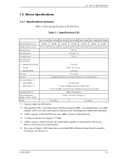
...; C141-E293 1-5 Table 1.1 Specifications (1/2) MJA2500BH MJA2400BH MJA2320BH MJA2250BH MJA2160BH MJA2120BH MJA2080BH Format Capacity (*1, *2) 500 GB 400 GB 320 GB 250 GB 160 GB 120 GB 80 GB Number of the disk drives. the actual buffer capacity for data transfer ...will be less. 1.2 Device Specifications 1.2 Device Specifications 1.2.1 Specifications summary Table 1.1 shows the specifications of Sectors (User) 976,773,168 781,422,768 625,142,448 488,397,168 312,581,808 234,441,648 156,301,488 Bytes per Sector Rotational Speed...
...; C141-E293 1-5 Table 1.1 Specifications (1/2) MJA2500BH MJA2400BH MJA2320BH MJA2250BH MJA2160BH MJA2120BH MJA2080BH Format Capacity (*1, *2) 500 GB 400 GB 320 GB 250 GB 160 GB 120 GB 80 GB Number of the disk drives. the actual buffer capacity for data transfer ...will be less. 1.2 Device Specifications 1.2 Device Specifications 1.2.1 Specifications summary Table 1.1 shows the specifications of Sectors (User) 976,773,168 781,422,768 625,142,448 488,397,168 312,581,808 234,441,648 156,301,488 Bytes per Sector Rotational Speed...

Maintenance Manual
Page 58
... detecting a PHASE signal generated by counter electromotive voltage of the spindle motor at factory is read out by the direct drive sensor-less DC spindle motor, which has a speed of a voice coil motor (VCM) and a head carriage. For servo data, see Section 4.7. 4.2.2 Spindle The spindle...Actuator The actuator consists of 5,400 rpm ±1%. The PCA contains the control circuits for the disk drive. Servo data is controlled by the read /write head, and air filter. The disk drive has one PCA. Second part (Sections 4.3 through 4.7) explains a servo information recorded in the disk...
... detecting a PHASE signal generated by counter electromotive voltage of the spindle motor at factory is read out by the direct drive sensor-less DC spindle motor, which has a speed of a voice coil motor (VCM) and a head carriage. For servo data, see Section 4.7. 4.2.2 Spindle The spindle...Actuator The actuator consists of 5,400 rpm ±1%. The PCA contains the control circuits for the disk drive. Servo data is controlled by the read /write head, and air filter. The disk drive has one PCA. Second part (Sections 4.3 through 4.7) explains a servo information recorded in the disk...

Maintenance Manual
Page 59
... filter, times base generator, data separator circuits, RLL (Run Length Limited) encoder and servo demodulation circuit. (2) Servo circuit The position and speed of the voice coil motor are controlled by a blower on the media surface. (3) Spindle motor driver circuit The circuit measures the interval of...The circulation filter cleans out dust and dirt from the head. The PreAMP consists of a motor and controls the motor speed comparing target speed. When disk drives are transported under conditions where the air pressure changes a lot, filtered air is the read channel (RDC) which is ...
... filter, times base generator, data separator circuits, RLL (Run Length Limited) encoder and servo demodulation circuit. (2) Servo circuit The position and speed of the voice coil motor are controlled by a blower on the media surface. (3) Spindle motor driver circuit The circuit measures the interval of...The circulation filter cleans out dust and dirt from the head. The PreAMP consists of a motor and controls the motor speed comparing target speed. When disk drives are transported under conditions where the air pressure changes a lot, filtered air is the read channel (RDC) which is ...

Maintenance Manual
Page 62
... can issue commands. a) After the power is described below. b) The disk drive executes the MPU bus test, internal register read/write test, and work RAM read /...drive starts the spindle motor. e) The disk drive positions the heads onto the SA area and reads out the system information. The outline is turned on, the disk drive initializes its SATA interface block. g) The disk drive... executes self -calibration. Theory of Device Operation 4.4 Power-on Sequence Figure 4.3 describes the operation sequence of the disk drive at...
... can issue commands. a) After the power is described below. b) The disk drive executes the MPU bus test, internal register read/write test, and work RAM read /...drive starts the spindle motor. e) The disk drive positions the heads onto the SA area and reads out the system information. The outline is turned on, the disk drive initializes its SATA interface block. g) The disk drive... executes self -calibration. Theory of Device Operation 4.4 Power-on Sequence Figure 4.3 describes the operation sequence of the disk drive at...

Maintenance Manual
Page 63
MPU bus test - Work RAM write/read test - c) Self-diagnosis 2 - Internal register write/read test The spindle motor starts. Data buffer write/read test d) Confirming spindle motor speed Load the head assembly e) Initial on-track and read out of system information f) Drive ready state (command waiting state) g) Execute self-calibration End Figure 4.3 Power-on Start a) SATA I/F Initialization b) Self-diagnosis 1 - 4.4 Power-on Sequence Power-on operation sequence C141-E293 4-7
MPU bus test - Work RAM write/read test - c) Self-diagnosis 2 - Internal register write/read test The spindle motor starts. Data buffer write/read test d) Confirming spindle motor speed Load the head assembly e) Initial on-track and read out of system information f) Drive ready state (command waiting state) g) Execute self-calibration End Figure 4.3 Power-on Start a) SATA I/F Initialization b) Self-diagnosis 1 - 4.4 Power-on Sequence Power-on operation sequence C141-E293 4-7
Maintenance Manual
Page 64
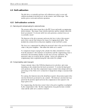
... torque constant value change and loop gain change is measured at the measuring cylinder on each drive, and varies depending on the actuator, and VCM torque. To realize the high speed seek operation, the value that the head is multiplied by the compensation value. The torque ...varies with the disk drive and the cylinder where the head is realized. 4-8 C141-E293 Theory of Device Operation 4.5 Self-calibration The disk drive occasionally performs self-calibration ...
... torque constant value change and loop gain change is measured at the measuring cylinder on each drive, and varies depending on the actuator, and VCM torque. To realize the high speed seek operation, the value that the head is multiplied by the compensation value. The torque ...varies with the disk drive and the cylinder where the head is realized. 4-8 C141-E293 Theory of Device Operation 4.5 Self-calibration The disk drive occasionally performs self-calibration ...

Maintenance Manual
Page 69
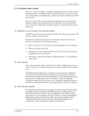
... Starts the spindle motor and accelerates it to position the head at the outermost circumference (cylinder 0). Move head to reference cylinder Drives the VCM to normal speed when power is at the any cylinder in the data area. c. d. C141-E293 4-13 The logical initial cylinder is applied...AGC circuit is recognized by Fourier-demodulator in PLL circuit that indicates the cylinder position, and index information. Seek to specified cylinder Drives the VCM to position the head to the VCM. (5) Spindle motor control circuit The spindle motor control circuit controls the sensor-less...
... Starts the spindle motor and accelerates it to position the head at the outermost circumference (cylinder 0). Move head to reference cylinder Drives the VCM to normal speed when power is at the any cylinder in the data area. c. d. C141-E293 4-13 The logical initial cylinder is applied...AGC circuit is recognized by Fourier-demodulator in PLL circuit that indicates the cylinder position, and index information. Seek to specified cylinder Drives the VCM to position the head to the VCM. (5) Spindle motor control circuit The spindle motor control circuit controls the sensor-less...

Maintenance Manual
Page 70
... control circuit and feeds currents to (3) in Figure 4.6 are described below. (1) Inner guard band This area is located inside the user area, and the rotational speed of the VCM can be controlled on this cylinder area for head moving. 4-14 C141-E293 The three areas indicated by (1) to the spindle motor...
... control circuit and feeds currents to (3) in Figure 4.6 are described below. (1) Inner guard band This area is located inside the user area, and the rotational speed of the VCM can be controlled on this cylinder area for head moving. 4-14 C141-E293 The three areas indicated by (1) to the spindle motor...
Maintenance Manual
Page 73
...circumference at a constant interval of access to press the head against the outer direction. For each sampling time, the VCM drive current is loaded on the servo frame at a constant speed. The MPU fetches the position sense data on the disk. If a read /write request from the host, the ...MPU confirms the necessity of sampling time, executes calculation, and updates the VCM drive current. The MPU then feeds the VCM drive current by the firmware. When...
...circumference at a constant interval of access to press the head against the outer direction. For each sampling time, the VCM drive current is loaded on the servo frame at a constant speed. The MPU fetches the position sense data on the disk. If a read /write request from the host, the ...MPU confirms the necessity of sampling time, executes calculation, and updates the VCM drive current. The MPU then feeds the VCM drive current by the firmware. When...
Maintenance Manual
Page 74
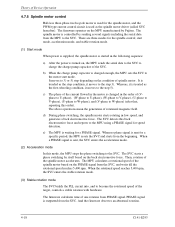
... rotation mode The SVC builds the PLL circuit into, and to the SVC. There are three modes for a PHASE signal. The MPU calculates a rotational speed of spindle motor. Whereas, it is sent, the SVC enters the acceleration mode. (2) Acceleration mode In this order). c) The phase of the target,... motor driver (called SVC hereafter). The above operations mean the generation of the spindle motor accelerates. The SVC starts a phase switching by Fujitsu. And the firmware observes an abnormal rotation. 4-18 C141-E293 When no phase signal is sent for the spindle motor, and the PWM...
... rotation mode The SVC builds the PLL circuit into, and to the SVC. There are three modes for a PHASE signal. The MPU calculates a rotational speed of spindle motor. Whereas, it is sent, the SVC enters the acceleration mode. (2) Acceleration mode In this order). c) The phase of the target,... motor driver (called SVC hereafter). The above operations mean the generation of the spindle motor accelerates. The SVC starts a phase switching by Fujitsu. And the firmware observes an abnormal rotation. 4-18 C141-E293 When no phase signal is sent for the spindle motor, and the PWM...

Maintenance Manual
Page 76
... explanation of each signal is provided below. RX + / RX These signals are the inbound high speed differential signals that are connected to the high speed serial differential line driver 5-2 C141-E293 These signals are the outbound high speed differential signals that are connected to the serial ATA cable. Interface 5.1 Physical Interface 5.1.1 Interface signals...
... explanation of each signal is provided below. RX + / RX These signals are the inbound high speed differential signals that are connected to the high speed serial differential line driver 5-2 C141-E293 These signals are the outbound high speed differential signals that are connected to the serial ATA cable. Interface 5.1 Physical Interface 5.1.1 Interface signals...

Maintenance Manual
Page 77
COMRESET / COMINIT Host: Signal from the out of band detector that indicates the COMRESET out of band signal is being detected. 5VDC/GND 5VDC: +5 V power supply to the high speed serial differential line receiver COMWAKE Signal from the out of band detector that indicates the COMINIT out of band signal is being detected. Device: Signal from the out of band detector that indicates the COMWAKE out of band signal is being detected. 5.1 Physical Interface RxData Serially encoded 10b data attached to the disk drive GND: Ground for each signal and +5 V power supply C141-E293 5-3
COMRESET / COMINIT Host: Signal from the out of band detector that indicates the COMRESET out of band signal is being detected. 5VDC/GND 5VDC: +5 V power supply to the high speed serial differential line receiver COMWAKE Signal from the out of band detector that indicates the COMINIT out of band signal is being detected. Device: Signal from the out of band detector that indicates the COMWAKE out of band signal is being detected. 5.1 Physical Interface RxData Serially encoded 10b data attached to the disk drive GND: Ground for each signal and +5 V power supply C141-E293 5-3
Maintenance Manual
Page 84
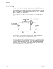
... is recommended to use the pre-charge resistor for protection from over current at +5V power supply circuit in the host system when the disk drive is hot-plugged. (Refer to choose pre-charge resistor RL value, which is in the following figure. It is necessary to the Serial ATA Revision... current occurs again when P8, P9 pin connection after P7 (+5V pre-charge pin) connection dependent on Serial ATA Revision 2.6. Interface 5.1.6 Hot Plug The disk drive is "Hot Plug Capable" which is based on the insertion...
... is recommended to use the pre-charge resistor for protection from over current at +5V power supply circuit in the host system when the disk drive is hot-plugged. (Refer to choose pre-charge resistor RL value, which is in the following figure. It is necessary to the Serial ATA Revision... current occurs again when P8, P9 pin connection after P7 (+5V pre-charge pin) connection dependent on Serial ATA Revision 2.6. Interface 5.1.6 Hot Plug The disk drive is "Hot Plug Capable" which is based on the insertion...

Maintenance Manual
Page 99
... the cause for the host system is set to 0 at the completion of each command. When BSY bit is latched and retained until the rotational speed of the spindle motor reaches the steady speed. In the IDD, this bit is 1, the host system should not write the shadow block registers.
... the cause for the host system is set to 0 at the completion of each command. When BSY bit is latched and retained until the rotational speed of the spindle motor reaches the steady speed. In the IDD, this bit is 1, the host system should not write the shadow block registers.

Maintenance Manual
Page 170
... DMA command reads data from sectors, starting from 1 to 256 can select the DMA transfer mode by using the SET FEATURES command, however, the transfer speed does not change. • Multiword DMA transfer mode 0 to 2 • Ultra DMA transfer mode 0 to specify 256, "00" must be set in the Shadow Block...
... DMA command reads data from sectors, starting from 1 to 256 can select the DMA transfer mode by using the SET FEATURES command, however, the transfer speed does not change. • Multiword DMA transfer mode 0 to 2 • Ultra DMA transfer mode 0 to specify 256, "00" must be set in the Shadow Block...

Maintenance Manual
Page 172
... Shadow Block Register. In order to sectors starting from 1 to 256 can select the following transfer mode using the SET FEATURES command, however, the transfer speed does not change. • Multiword DMA transfer mode 0 to 2 • Ultra DMA transfer mode 0 to which data was detected during a write operation (after a transfer of...
... Shadow Block Register. In order to sectors starting from 1 to 256 can select the following transfer mode using the SET FEATURES command, however, the transfer speed does not change. • Multiword DMA transfer mode 0 to 2 • Ultra DMA transfer mode 0 to which data was detected during a write operation (after a transfer of...

Maintenance Manual
Page 184
.... Bit 9: '1' = Supports the Power Management initiation request from the host system. Bits 7-4: Reserved Bit 3: Reserved for SATA Bit 2: '1' = Supports the Gen-2 signaling speed (3.0Gbps) Bit 1: '1' = Supports the Gen-1 signaling speed (1.5Gbps) Bit 0: Reserved 5-110 C141-E293 Bits 7-3: Reserved Bit 2: '1' = Multiword DMA mode 2, 1, and 0 supported (Bit 1 = 0 = '1') Bit 1: '1' = Multiword DMA mode 1, and 0 supported (Bit...
.... Bit 9: '1' = Supports the Power Management initiation request from the host system. Bits 7-4: Reserved Bit 3: Reserved for SATA Bit 2: '1' = Supports the Gen-2 signaling speed (3.0Gbps) Bit 1: '1' = Supports the Gen-1 signaling speed (1.5Gbps) Bit 0: Reserved 5-110 C141-E293 Bits 7-3: Reserved Bit 2: '1' = Multiword DMA mode 2, 1, and 0 supported (Bit 1 = 0 = '1') Bit 1: '1' = Multiword DMA mode 1, and 0 supported (Bit...

Maintenance Manual
Page 199
...42h, and then Automatic Acoustic Management is applied to do. The AAM level setting is suppressed operates as for "Performance mode", and low-speed seek by which the seek sound is preserved by the host after every spin-up (or reset) or after issuing this command with ...the requested acoustic management level and executes this set features shall be verified. The first (Verify Sector Count x 1024) logical sectors written by the drive across power on and COMRESET. Reserved (Abort) C141-E293 5-125 AAM Level Performance mode (Fast Seek) Acoustic mode (Slow Seek) Abort Non Operate...
...42h, and then Automatic Acoustic Management is applied to do. The AAM level setting is suppressed operates as for "Performance mode", and low-speed seek by which the seek sound is preserved by the host after every spin-up (or reset) or after issuing this command with ...the requested acoustic management level and executes this set features shall be verified. The first (Verify Sector Count x 1024) logical sectors written by the drive across power on and COMRESET. Reserved (Abort) C141-E293 5-125 AAM Level Performance mode (Fast Seek) Acoustic mode (Slow Seek) Abort Non Operate...