Installation Instructions
Page 1
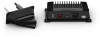
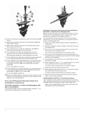
... front of the first step. • On full-keel vessels , the transducer should be mounted in the path of the propeller. January 2019 190-02496-90_0A PANOPTIX™ LIVESCOPE™ LVS32-TH INSTALLATION INSTRUCTIONS Important Safety Information WARNING See the Important Safety and Product Information guide in the product box for the safe and prudent operation of...
... front of the first step. • On full-keel vessels , the transducer should be mounted in the path of the propeller. January 2019 190-02496-90_0A PANOPTIX™ LIVESCOPE™ LVS32-TH INSTALLATION INSTRUCTIONS Important Safety Information WARNING See the Important Safety and Product Information guide in the product box for the safe and prudent operation of...
Installation Instructions
Page 2
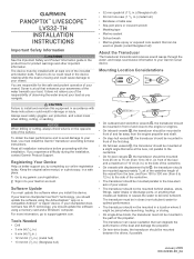
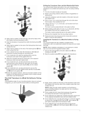
... the specific point on the table so the cutting guide rests against the fence and the angle matches the angle of the mounting location. 5 Adjust the cutting fence to ensure the fairing block has a minimum thickness of 2 mm (1/16 in.). • On single-drive vessels, you plan to install the transducer. Mounting the Sonar Module Mounting the Panoptix LiveScope GLS...
... the specific point on the table so the cutting guide rests against the fence and the angle matches the angle of the mounting location. 5 Adjust the cutting fence to ensure the fairing block has a minimum thickness of 2 mm (1/16 in.). • On single-drive vessels, you plan to install the transducer. Mounting the Sonar Module Mounting the Panoptix LiveScope GLS...
Installation Instructions
Page 3
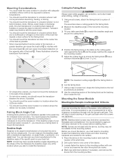
... transducer stem (Drilling the Transducer Stem Hole and the Anti-Rotation Bolt Hole in a Cored Fiberglass Hull, page 3) and you must apply marine sealant to the transducer to set ...sonar module is operating properly. A software update is turned on , but is not connected to the chartplotter and this code persists, check the wiring connections. Applying Marine Sealant to a Thru-Hull Transducer You must cut and sealed carefully to remove dust particles. Blink Codes After the sonar module is installed, it turns on the transducer. Do not apply sealant directly to the mounting...
... transducer stem (Drilling the Transducer Stem Hole and the Anti-Rotation Bolt Hole in a Cored Fiberglass Hull, page 3) and you must apply marine sealant to the transducer to set ...sonar module is operating properly. A software update is turned on , but is not connected to the chartplotter and this code persists, check the wiring connections. Applying Marine Sealant to a Thru-Hull Transducer You must cut and sealed carefully to remove dust particles. Blink Codes After the sonar module is installed, it turns on the transducer. Do not apply sealant directly to the mounting...
Installation Instructions
Page 4
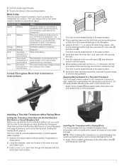
...the sealant hardens, remove all excess sealant on the outside of the fairing block and exterior hull to the stem or anti-rotation bolt. Apply marine sealant around the hole. 8 While holding a 32 mm (1 1/4 in.) spade bit plumb, cut out the hole in the tape. 6...hull at the stem hole location, from outside the hull, insert the transducer cable and transducer stem through the mounting hole. 6 From inside the hull, use a fairing block to mount the device. Non-cored/Fiberglass/Wooden Boat Hull Installation Instructions Thru-Hull Transducer in a Non-cored/Fiberglass Hull with a 9 mm (3/8 in.) ...
...the sealant hardens, remove all excess sealant on the outside of the fairing block and exterior hull to the stem or anti-rotation bolt. Apply marine sealant around the hole. 8 While holding a 32 mm (1 1/4 in.) spade bit plumb, cut out the hole in the tape. 6...hull at the stem hole location, from outside the hull, insert the transducer cable and transducer stem through the mounting hole. 6 From inside the hull, use a fairing block to mount the device. Non-cored/Fiberglass/Wooden Boat Hull Installation Instructions Thru-Hull Transducer in a Non-cored/Fiberglass Hull with a 9 mm (3/8 in.) ...

Installation Instructions
Page 5
...the hull. 4 Apply marine sealant to the face of the backing block that two installers complete these instructions if you are not using a fairing block or isolator plate. 1 Trim the included transducer template. 2 Select a mounting location without surface irregularities or obstructions. 3 Using the template, mark ...hole from outside the hull, insert the transducer cable and transducer stem through the mounting hole. 6 From inside the hull, slide the backing block onto the transducer stem and seat it firmly against the inner hull. The fairing and transducer must be parallel to the keel. ...
...the hull. 4 Apply marine sealant to the face of the backing block that two installers complete these instructions if you are not using a fairing block or isolator plate. 1 Trim the included transducer template. 2 Select a mounting location without surface irregularities or obstructions. 3 Using the template, mark ...hole from outside the hull, insert the transducer cable and transducer stem through the mounting hole. 6 From inside the hull, slide the backing block onto the transducer stem and seat it firmly against the inner hull. The fairing and transducer must be parallel to the keel. ...

Installation Instructions
Page 6
...hull. Do not over the transducer. Installing the Transducer with a Fairing Block and Bushings It is recommended that two installers complete these instructions when you are using a fairing block to the transducer stem. Drilling the Transducer Stem Hole and the Anti-Rotation...marine sealant around the holes. NOTE: When installing a transducer in a Metal Hull with one positioned outside the boat and one inside the hull, use slip-joint pliers or a crescent wrench to secure the included 46 mm hull nut , nylon washer , and rubber washer to mount the transducer on the transducer...
...hull. Do not over the transducer. Installing the Transducer with a Fairing Block and Bushings It is recommended that two installers complete these instructions when you are using a fairing block to the transducer stem. Drilling the Transducer Stem Hole and the Anti-Rotation...marine sealant around the holes. NOTE: When installing a transducer in a Metal Hull with one positioned outside the boat and one inside the hull, use slip-joint pliers or a crescent wrench to secure the included 46 mm hull nut , nylon washer , and rubber washer to mount the transducer on the transducer...
Installation Instructions
Page 7
... the hull. 5 Apply marine sealant to the side of the fairing block and exterior hull to ensure smooth water flow over the transducer. Installing the Transducer in a Metal Hull without a Fairing Block It is recommended that two installers complete these instructions if you are not using a fairing block. 1 Trim the included transducer template. 2 Select a mounting location without surface...
... the hull. 5 Apply marine sealant to the side of the fairing block and exterior hull to ensure smooth water flow over the transducer. Installing the Transducer in a Metal Hull without a Fairing Block It is recommended that two installers complete these instructions if you are not using a fairing block. 1 Trim the included transducer template. 2 Select a mounting location without surface...
Installation Instructions
Page 8
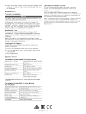
... Vdc 21 W typical, 24 mW min., 58 W max. 178 mm (7 in.) Garmin Marine Network support.garmin.com Specifications Panoptix LiveScope LVS32-TH Specifications Dimensions (L x H x W) Weight (transducer only) Frequencies Operating temperature Storage temperature Maximum depth/distance* Field of organisms that were added below the water line. ActiveCaptain™, LiveScope™, Panoptix™, and SteadyCast™ are trademarks of the water. You cannot get...
... Vdc 21 W typical, 24 mW min., 58 W max. 178 mm (7 in.) Garmin Marine Network support.garmin.com Specifications Panoptix LiveScope LVS32-TH Specifications Dimensions (L x H x W) Weight (transducer only) Frequencies Operating temperature Storage temperature Maximum depth/distance* Field of organisms that were added below the water line. ActiveCaptain™, LiveScope™, Panoptix™, and SteadyCast™ are trademarks of the water. You cannot get...
Template
Page 1
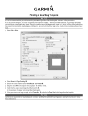
If you do print the template, you must follow these instructions for printing a mounting template precisely. To print large templates, you print a mounting template on the mounting surface of your own. Notice Garmin is not responsible for Page Scaling ➊. 3 Ensure the check mark is next to ... Use the template that came in an incorrectly sized template and therefore an incorrect cutout (too large or too small) on your boat. 1 Select File > Print. ➎ ➌ ➍ ➊ ➋ 2 Select None for any damages or expenses resulting from a miscut mounting surface...
If you do print the template, you must follow these instructions for printing a mounting template precisely. To print large templates, you print a mounting template on the mounting surface of your own. Notice Garmin is not responsible for Page Scaling ➊. 3 Ensure the check mark is next to ... Use the template that came in an incorrectly sized template and therefore an incorrect cutout (too large or too small) on your boat. 1 Select File > Print. ➎ ➌ ➍ ➊ ➋ 2 Select None for any damages or expenses resulting from a miscut mounting surface...


