
Flush Mount Template
Page 1
...correct orientation. Properties: Select the paper size. Select Auto-Rotate and Center to None. Notice After printing and before cutting the mounting surface, measure the printed template to ensure both the length and the width printed at the correct size and to follow these instructions...and Center: Select with a check mark for correct orientation Paper size (example): Use appropriate size paper. Garmin is not responsible for any damages or expenses resulting from a miscut mounting surface arising from a failure to ensure that the dimensions of the printed template match the actual size of...
...correct orientation. Properties: Select the paper size. Select Auto-Rotate and Center to None. Notice After printing and before cutting the mounting surface, measure the printed template to ensure both the length and the width printed at the correct size and to follow these instructions...and Center: Select with a check mark for correct orientation Paper size (example): Use appropriate size paper. Garmin is not responsible for any damages or expenses resulting from a miscut mounting surface arising from a failure to ensure that the dimensions of the printed template match the actual size of...

Flush Mount Template
Page 2
141.5 mm (5.57 in.) GMR™ 18/24 Mounting Template 9.5 mm (3/8 in.) February 2014 233.0 mm (9.17 in.) 190-00831-05_0B Printed in Taiwan
141.5 mm (5.57 in.) GMR™ 18/24 Mounting Template 9.5 mm (3/8 in.) February 2014 233.0 mm (9.17 in.) 190-00831-05_0B Printed in Taiwan

Installation Instructions
Page 3
...of anti-seize compound • Mounting template • Grommet for marine cable Garmin Radome Installation Instructions 1 Introduction Thank you by phone: (913) 397-8200 or (800) 800-1020 or go to an authorized Garmin NMEA dealer or contact Garmin Product Support for repairs. Product Registration... • Power cable • Marine network cable • Field install RJ-45 network cable connector • Mounting kit hardware • Packet of Garmin radar and provides overlay and color information when combined with your unit, check that your package includes the following items....
...of anti-seize compound • Mounting template • Grommet for marine cable Garmin Radome Installation Instructions 1 Introduction Thank you by phone: (913) 397-8200 or (800) 800-1020 or go to an authorized Garmin NMEA dealer or contact Garmin Product Support for repairs. Product Registration... • Power cable • Marine network cable • Field install RJ-45 network cable connector • Mounting kit hardware • Packet of Garmin radar and provides overlay and color information when combined with your unit, check that your package includes the following items....
Installation Instructions
Page 4
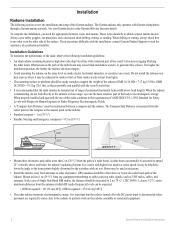
...installation, you experience difficulty with the installation, contact Garmin Product Support or seek the assistance of the Garmin radome. eyes are required to come close range; A radar beam can detect targets. • Avoid mounting the radome on the same level as VHF ...or crosstrees on the radome assembly or associated equipment. 2 Garmin Radome Installation Instructions These items should be increased to 2 m (78 3/4" ). It is important that the radar radome be mounted out of range of a radar beam. Installation Radome Installation The following installation guidelines: &#...
...installation, you experience difficulty with the installation, contact Garmin Product Support or seek the assistance of the Garmin radome. eyes are required to come close range; A radar beam can detect targets. • Avoid mounting the radome on the same level as VHF ...or crosstrees on the radome assembly or associated equipment. 2 Garmin Radome Installation Instructions These items should be increased to 2 m (78 3/4" ). It is important that the radar radome be mounted out of range of a radar beam. Installation Radome Installation The following installation guidelines: &#...

Installation Instructions
Page 5
... locations are aligned fore and aft, and use the included mounting template or reference Figure 1 to the mounting surface using a pre-drilled Garmin compatible or Raymarine® mount.) 2. Fasten the radome to drill four 9.5 mm (7/16") mounting holes. (This step is firmly sealed. 3. Mounting the Radome 1. Press the 2-pin power cable to the power connector and...
... locations are aligned fore and aft, and use the included mounting template or reference Figure 1 to the mounting surface using a pre-drilled Garmin compatible or Raymarine® mount.) 2. Fasten the radome to drill four 9.5 mm (7/16") mounting holes. (This step is firmly sealed. 3. Mounting the Radome 1. Press the 2-pin power cable to the power connector and...

Installation Instructions
Page 6
...on the GMS 10 network port expander. This diagram only illustrates the network data connections. 4 Garmin Radome Installation Instructions Cable Runs Route the cables as needed, depending on the type of mount you are connected to the new RJ-45 connector the same way. • To ensure... wiring connections 1. Removing the inline fuse holder may be necessary to drill 31.7 mm (1.25") holes for the Garmin radome to function correctly. For an expanded network (chartplotter, radar, GMS 10, etc.), attach the RJ-45 marine network cable to the vessel's negative power terminal. 2. Note:...
...on the GMS 10 network port expander. This diagram only illustrates the network data connections. 4 Garmin Radome Installation Instructions Cable Runs Route the cables as needed, depending on the type of mount you are connected to the new RJ-45 connector the same way. • To ensure... wiring connections 1. Removing the inline fuse holder may be necessary to drill 31.7 mm (1.25") holes for the Garmin radome to function correctly. For an expanded network (chartplotter, radar, GMS 10, etc.), attach the RJ-45 marine network cable to the vessel's negative power terminal. 2. Note:...

