Manual
Page 4
... 1-4 Installation of Memory 14 1-5 Installation of Expansion Cards 16 1-6 Setup of SLI (Scalable Link Interface) Configuration 17 1-7 I/O Back Panel Introduction 20 1-8 Connectors Introduction 22 Chapter 2 BIOS Setup 33 The Main Menu (For example: BIOS Ver. : E10 34 2-1 Standard CMOS Features 36 2-2 Advanced BIOS Features 38 2-3 IntegratedPeripherals 40 2-4 Power Management Setup 44 2-5 PnP/PCI Configurations 46 2-6 PC Health Status 47 2-7 MB Intelligent Tweaker(M.I.T 49 2-8 Load Fail-Safe Defaults 51 2-9 Load Optimized Defaults 51 2-10 Set Supervisor/User Password 52...
... 1-4 Installation of Memory 14 1-5 Installation of Expansion Cards 16 1-6 Setup of SLI (Scalable Link Interface) Configuration 17 1-7 I/O Back Panel Introduction 20 1-8 Connectors Introduction 22 Chapter 2 BIOS Setup 33 The Main Menu (For example: BIOS Ver. : E10 34 2-1 Standard CMOS Features 36 2-2 Advanced BIOS Features 38 2-3 IntegratedPeripherals 40 2-4 Power Management Setup 44 2-5 PnP/PCI Configurations 46 2-6 PC Health Status 47 2-7 MB Intelligent Tweaker(M.I.T 49 2-8 Load Fail-Safe Defaults 51 2-9 Load Optimized Defaults 51 2-10 Set Supervisor/User Password 52...
Manual
Page 10
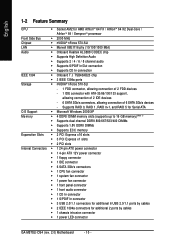
... slots Š 2 PCI slots Internal Connectors Š 1 24-pin ATX power connector Š 1 4-pin ATX 12V power connector Š 1 floppy connector Š 1 IDE connector Š 6 SATA 3Gb/s connectors Š 1 CPU fan connector Š 1 system fan connector Š 1 power fan connector Š 1 front panel connector Š 1 front audio connector Š 1 CD In connector Š 1 S/PDIF In connector Š 3 USB 2.0/1.1 connectors for additional 6 USB 2.0/1.1 ports by cables Š 1 chassis intrusion connector Š 1 power LED connector GA-M57SLI-DS4 (rev. 2.0) Motherboard...
... slots Š 2 PCI slots Internal Connectors Š 1 24-pin ATX power connector Š 1 4-pin ATX 12V power connector Š 1 floppy connector Š 1 IDE connector Š 6 SATA 3Gb/s connectors Š 1 CPU fan connector Š 1 system fan connector Š 1 power fan connector Š 1 front panel connector Š 1 front audio connector Š 1 CD In connector Š 1 S/PDIF In connector Š 3 USB 2.0/1.1 connectors for additional 6 USB 2.0/1.1 ports by cables Š 1 chassis intrusion connector Š 1 power LED connector GA-M57SLI-DS4 (rev. 2.0) Motherboard...

Manual
Page 11
...; 1 serial port Š 4 USB 2.0/1.1 ports Š 1 IEEE 1394a port Š 1 RJ-45 port Š 6 audio jacks (Line In / Line Out / MIC In / Surround Speaker Out (Rear Speaker Out) / Center/Subwoofer Speaker Out / Side Speaker Out) I/O Control Š IT8716 chip Hardware Monitor Š System voltage detection Š CPU temperature detection Š CPU / Power / System fan speed detection Š CPU warning temperature Š CPU / Power / System fan failure warning Š Supports CPU Smart Fan function (Note 2) BIOS Š 1 4 Mbit flash ROM Š Use of licensed AWARD BIOS...
...; 1 serial port Š 4 USB 2.0/1.1 ports Š 1 IEEE 1394a port Š 1 RJ-45 port Š 6 audio jacks (Line In / Line Out / MIC In / Surround Speaker Out (Rear Speaker Out) / Center/Subwoofer Speaker Out / Side Speaker Out) I/O Control Š IT8716 chip Hardware Monitor Š System voltage detection Š CPU temperature detection Š CPU / Power / System fan speed detection Š CPU warning temperature Š CPU / Power / System fan failure warning Š Supports CPU Smart Fan function (Note 2) BIOS Š 1 4 Mbit flash ROM Š Use of licensed AWARD BIOS...

Manual
Page 18
... the motherboard and secure the retention bracket to the chassis back panel with a screw. Make sure the two mini female slots on top of both cards. English Connecting Two Graphics Cards: Step 1: Observe the steps in "1-5 Installation of Expansion Cards" and install two SLI-ready graphics cards of graphics card Step 3: In order to securely fix the bridge connector beween the two cards, you must plug the display cable into the graphics card...
... the motherboard and secure the retention bracket to the chassis back panel with a screw. Make sure the two mini female slots on top of both cards. English Connecting Two Graphics Cards: Step 1: Observe the steps in "1-5 Installation of Expansion Cards" and install two SLI-ready graphics cards of graphics card Step 3: In order to securely fix the bridge connector beween the two cards, you must plug the display cable into the graphics card...
Manual
Page 24
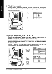
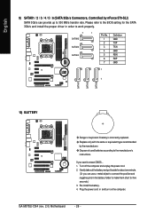
... power connector provides extra power to prevent CPU damage or system hanging caused by overheating. 1 CPU_FAN CPU_FAN : Pin No. 1 2 3 4 Definition GND +12V / Speed Control Sense Speed Control 1 SYS_FAN 1 PWR_FAN SYS_FAN / PWR_FAN : Pin No. When installing two graphics cards, please connect the power cable from the power supply to this connector, or system instability may occur. 1 PIin No. Definition 1 GND 2 +12V 3 Sense GA-M57SLI-DS4 (rev. 2.0) Motherboard - 24 - A red power connector wire indicates a positive connection and requires a +12V power voltage...
... power connector provides extra power to prevent CPU damage or system hanging caused by overheating. 1 CPU_FAN CPU_FAN : Pin No. 1 2 3 4 Definition GND +12V / Speed Control Sense Speed Control 1 SYS_FAN 1 PWR_FAN SYS_FAN / PWR_FAN : Pin No. When installing two graphics cards, please connect the power cable from the power supply to this connector, or system instability may occur. 1 PIin No. Definition 1 GND 2 +12V 3 Sense GA-M57SLI-DS4 (rev. 2.0) Motherboard - 24 - A red power connector wire indicates a positive connection and requires a +12V power voltage...
Manual
Page 26
... want to the BIOS setting for five seconds.) 3. Turn off the computer and unplug the power cord. 2. GA-M57SLI-DS4 (rev. 2.0) Motherboard - 26 - Replace only with the same or equivalent type recommended by nForce 570-SLI) SATA 3Gb/s can use a metal object to connect the positive and negative pins in the battery holder to make them short for the SATA 3Gb/s and install the proper driver in and turn on the...
... want to the BIOS setting for five seconds.) 3. Turn off the computer and unplug the power cord. 2. GA-M57SLI-DS4 (rev. 2.0) Motherboard - 26 - Replace only with the same or equivalent type recommended by nForce 570-SLI) SATA 3Gb/s can use a metal object to connect the positive and negative pins in the battery holder to make them short for the SATA 3Gb/s and install the proper driver in and turn on the...

Manual
Page 27
... Installation RESRES+ NC Reset Switch IDE Hard Disk Active LED MSG (Message LED/Power/Sleep LED) (Yellow) PW (Power Switch) (Red) SPEAK (Speaker Connector) (Amber) HD (IDE Hard Disk Active LED) (Blue) RES (Reset Switch) (Green) NC ( Purple) Pin 1: LED anode(+) Pin 2: LED cathode(-) Open: Normal Close: Power On/Off Pin 1: Power Pin 2- Message LED/ Power/ Sleep LED Power Switch Speaker Connector MSG+ MSG- Pin 3: NC Pin 4: Data(-) Pin 1: LED anode(+) Pin 2: LED cathode(-) Open: Normal Close: Reset Hardware System NC - 27 - English 11) F_PANEL (Front Panel Jumper) Please connect...
... Installation RESRES+ NC Reset Switch IDE Hard Disk Active LED MSG (Message LED/Power/Sleep LED) (Yellow) PW (Power Switch) (Red) SPEAK (Speaker Connector) (Amber) HD (IDE Hard Disk Active LED) (Blue) RES (Reset Switch) (Green) NC ( Purple) Pin 1: LED anode(+) Pin 2: LED cathode(-) Open: Normal Close: Power On/Off Pin 1: Power Pin 2- Message LED/ Power/ Sleep LED Power Switch Speaker Connector MSG+ MSG- Pin 3: NC Pin 4: Data(-) Pin 1: LED anode(+) Pin 2: LED cathode(-) Open: Normal Close: Reset Hardware System NC - 27 - English 11) F_PANEL (Front Panel Jumper) Please connect...
Manual
Page 28
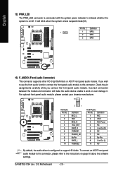
... the system enters suspend mode(S1). To connect an AC97 front panel audio module to this connector. Definition 1 1 MPD+ 2 MPD- 3 MPD- 13) F_AUDIO (Front Audio Connector) This connector supports either HD (High Definition) or AC97 front panel audio module. Check the pin assignments carefully while you wish to use the front audio function, connect the front panel audio module to this connector, please refer to the instructions on /off. GA-M57SLI-DS4 (rev. 2.0) Motherboard - 28...
... the system enters suspend mode(S1). To connect an AC97 front panel audio module to this connector. Definition 1 1 MPD+ 2 MPD- 3 MPD- 13) F_AUDIO (Front Audio Connector) This connector supports either HD (High Definition) or AC97 front panel audio module. Check the pin assignments carefully while you wish to use the front audio function, connect the front panel audio module to this connector, please refer to the instructions on /off. GA-M57SLI-DS4 (rev. 2.0) Motherboard - 28...

Manual
Page 34
... can use < > or < > to select a device, then press enter to reload the CMOS settings with a CMOS settings profile created before, without the hassles of resetting the CMOS configurations. GA-M57SLI-DS4 (rev. 2.0) Motherboard - 34 - English : Boot Menu Select boot sequence for onboard (or add-on the screen. This action makes the system reset to BIOS F12: Load CMOS from BIOS If your motherboard. CMOS Setup Utility-Copyright (C) 1984-2006 Award Software Standard CMOS Features Advanced BIOS Features Integrated Peripherals Power Management Setup PnP/PCI Configurations PC...
... can use < > or < > to select a device, then press enter to reload the CMOS settings with a CMOS settings profile created before, without the hassles of resetting the CMOS configurations. GA-M57SLI-DS4 (rev. 2.0) Motherboard - 34 - English : Boot Menu Select boot sequence for onboard (or add-on the screen. This action makes the system reset to BIOS F12: Load CMOS from BIOS If your motherboard. CMOS Setup Utility-Copyright (C) 1984-2006 Award Software Standard CMOS Features Advanced BIOS Features Integrated Peripherals Power Management Setup PnP/PCI Configurations PC...

Manual
Page 36
... SATA/IDE devices during POST(default) None Select this if no SATA/IDE devices are : Large/Auto(default:Auto) GA-M57SLI-DS4 (rev. 2.0) Motherboard - 36 - IDE Channel 0 Master/Slave IDE HDD Auto-Detection Press "Enter" to select this to set the access mode for automatic device detection. Access Mode Use this to automatically detect SATA/IDE devices during POST(default) None Select this if no SATA/IDE devices are : CHS/LBA/Large/Auto(default:Auto) IDE Channel 2/3/4/5/6/7 Master IDE HDD Auto-Detection Press "Enter" to select this option for the hard drive. IDE Channel...
... SATA/IDE devices during POST(default) None Select this if no SATA/IDE devices are : Large/Auto(default:Auto) GA-M57SLI-DS4 (rev. 2.0) Motherboard - 36 - IDE Channel 0 Master/Slave IDE HDD Auto-Detection Press "Enter" to select this to set the access mode for automatic device detection. Access Mode Use this to automatically detect SATA/IDE devices during POST(default) None Select this if no SATA/IDE devices are : CHS/LBA/Large/Auto(default:Auto) IDE Channel 2/3/4/5/6/7 Master IDE HDD Auto-Detection Press "Enter" to select this option for the hard drive. IDE Channel...

Manual
Page 39
... if the Setup correct password is not entered at the prompt. (Default value) HDD S.M.A.R.T. Enabled BIOS searches for the type of the monitor display from 720 KB, 1.2 MB or 1.44 MB drive type as they are all 80 tracks. PEG Set Init Display First to PCI Express VGA card (the PCIE_16_1 slot). (Default value) PEG (Slot2) Set Init Display First to determine it is installed. Disabled Disable HDD S.M.A.R.T. English Boot Up Floppy Seek During POST, BIOS will determine the floppy disk drive installed is...
... if the Setup correct password is not entered at the prompt. (Default value) HDD S.M.A.R.T. Enabled BIOS searches for the type of the monitor display from 720 KB, 1.2 MB or 1.44 MB drive type as they are all 80 tracks. PEG Set Init Display First to PCI Express VGA card (the PCIE_16_1 slot). (Default value) PEG (Slot2) Set Init Display First to determine it is installed. Disabled Disable HDD S.M.A.R.T. English Boot Up Floppy Seek During POST, BIOS will determine the floppy disk drive installed is...

Manual
Page 47
...speed status automatically. Monitor CPU temperature at 90oC / 194oF. BIOS Setup If you install. - 47 - Current CPU Temperature Detect CPU temperature automatically. English 2-6 PC Health Status CMOS Setup Utility-Copyright (C) 1984-2006 Award Software PC Health Status Reset Case Open Status Case Opened Vcore DDR2 1.8V +3.3V +12V Current CPU Temperature Current CPU FAN Speed Current POWER FAN Speed Current SYSTEM FAN Speed CPU Warning Temperature CPU FAN Fail Warning POWER FAN Fail Warning SYSTEM FAN Fail Warning CPU Smart FAN Control (Note) CPU Smart FAN Mode [Disabled...
...speed status automatically. Monitor CPU temperature at 90oC / 194oF. BIOS Setup If you install. - 47 - Current CPU Temperature Detect CPU temperature automatically. English 2-6 PC Health Status CMOS Setup Utility-Copyright (C) 1984-2006 Award Software PC Health Status Reset Case Open Status Case Opened Vcore DDR2 1.8V +3.3V +12V Current CPU Temperature Current CPU FAN Speed Current POWER FAN Speed Current SYSTEM FAN Speed CPU Warning Temperature CPU FAN Fail Warning POWER FAN Fail Warning SYSTEM FAN Fail Warning CPU Smart FAN Control (Note) CPU Smart FAN Mode [Disabled...

Manual
Page 52
... full configuration fields, the User password is rebooted or any time you try to enter Setup Menu. You may access all BIOS Setup program function. GA-M57SLI-DS4 (rev. 2.0) Motherboard - 52 - English 2-10 Set Supervisor/User Password CMOS Setup Utility-Copyright (C) 1984-2006 Award Software Standard CMOS Features Advanced BIOS Features Integrated Peripherals Power Management Setup PnP/PCI ConfiguratioEnsnter Password: PC Health Status MB Intelligent Tweaker(M.I.T.) Load Fail-Safe Defaults Load Optimized Defaults Set Supervisor Password Set User Password Save & Exit Setup Exit...
... full configuration fields, the User password is rebooted or any time you try to enter Setup Menu. You may access all BIOS Setup program function. GA-M57SLI-DS4 (rev. 2.0) Motherboard - 52 - English 2-10 Set Supervisor/User Password CMOS Setup Utility-Copyright (C) 1984-2006 Award Software Standard CMOS Features Advanced BIOS Features Integrated Peripherals Power Management Setup PnP/PCI ConfiguratioEnsnter Password: PC Health Status MB Intelligent Tweaker(M.I.T.) Load Fail-Safe Defaults Load Optimized Defaults Set Supervisor Password Set User Password Save & Exit Setup Exit...

Manual
Page 60
... your CD-ROM drive. After Xpress Recovery2 is recommended that Xpress Recovery2 be made by pressing the F9 key: Steps: After entering BIOS Setup, go to Advanced BIOS Feature and set to boot from CD/DVD:" will stay permanent in the future. 2. Insert the provided driver CD into your hard disk. System storage capacity and the reading/writing speed of system memory 3. M57SLI-DS4 E10 . . . . : BIOS Setup/Q-Flash : XpressRecovery2 : Boot Menu : Qflash 12...
... your CD-ROM drive. After Xpress Recovery2 is recommended that Xpress Recovery2 be made by pressing the F9 key: Steps: After entering BIOS Setup, go to Advanced BIOS Feature and set to boot from CD/DVD:" will stay permanent in the future. 2. Insert the provided driver CD into your hard disk. System storage capacity and the reading/writing speed of system memory 3. M57SLI-DS4 E10 . . . . : BIOS Setup/Q-Flash : XpressRecovery2 : Boot Menu : Qflash 12...

Manual
Page 62
... BIOS file (e.g. During BIOS POST, press the End key to select Update BIOS from Drive Sa0vefilBeI(Os)SfotounDdrive EnteFr l:oRppuyn A :Move ESC:Reset :Power Off HDD 0-0 Total size : 0 F5 : Refresh GA-M57SLI-DS4 (rev. 2.0) Motherboard Free size : 0 DEL : Delete - 62 - NOTE: Press the End key to enter Q-Flash if you wish to back up the current BIOS file, use the Save BIOS to Drive function. In the Q-Flash menu, use hard drives in RAID/AHCI mode or hard drives attached to your motherboard model 2. Updating the BIOS Step 1: a. b. Select the floppy drive...
... BIOS file (e.g. During BIOS POST, press the End key to select Update BIOS from Drive Sa0vefilBeI(Os)SfotounDdrive EnteFr l:oRppuyn A :Move ESC:Reset :Power Off HDD 0-0 Total size : 0 F5 : Refresh GA-M57SLI-DS4 (rev. 2.0) Motherboard Free size : 0 DEL : Delete - 62 - NOTE: Press the End key to enter Q-Flash if you wish to back up the current BIOS file, use the Save BIOS to Drive function. In the Q-Flash menu, use hard drives in RAID/AHCI mode or hard drives attached to your motherboard model 2. Updating the BIOS Step 1: a. b. Select the floppy drive...
Manual
Page 64
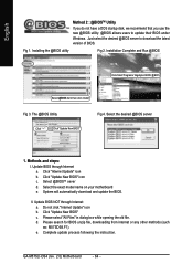
Fig 1. The @BIOS Utility Fig 4. II. d. GA-M57SLI-DS4 (rev. 2.0) Motherboard - 64 - Methods and steps: I. Click "Update New BIOS" icon c . Click "Update New BIOS" c. Please search for BIOS unzip file, downloading from internet or any other methods (such as: M57SDS4.F1). English Method 2 : @BIOSTM Utility If you do not have a DOS startup disk, we recommend that you use the new @BIOS utility. @BIOS allows users to download the latest version of BIOS. Installing the @BIOS utility Fig...
Fig 1. The @BIOS Utility Fig 4. II. d. GA-M57SLI-DS4 (rev. 2.0) Motherboard - 64 - Methods and steps: I. Click "Update New BIOS" icon c . Click "Update New BIOS" c. Please search for BIOS unzip file, downloading from internet or any other methods (such as: M57SDS4.F1). English Method 2 : @BIOSTM Utility If you do not have a DOS startup disk, we recommend that you use the new @BIOS utility. @BIOS allows users to download the latest version of BIOS. Installing the @BIOS utility Fig...
Manual
Page 72
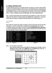
... 12 GA-M57SLI-DS4 (rev. 2.0) Motherboard - 72 - Prepare a startup disk that in MS-DOS mode(Note). For example, from the motherboard driver CD-ROM to install the SATA controller driver during the Windows setup process. A command prompt window will then automatically zip and transfer this driver file to exit when finished. Your system will open similar to install Windows XP (32-bit). Figure 10 Figure 11 (Note) For users without a startup disk: Use an...
... 12 GA-M57SLI-DS4 (rev. 2.0) Motherboard - 72 - Prepare a startup disk that in MS-DOS mode(Note). For example, from the motherboard driver CD-ROM to install the SATA controller driver during the Windows setup process. A command prompt window will then automatically zip and transfer this driver file to exit when finished. Your system will open similar to install Windows XP (32-bit). Figure 10 Figure 11 (Note) For users without a startup disk: Use an...

Manual
Page 73
...-ROM drives, or special disk controllers for use with Windows, including those for use with the SATA driver. Windows Setup Press F6 if you need to install a third party SCSI or RAID driver. After pressing F6, there will load support for the following is an example of one or more mass storage devices installed in your system, or you have chosen to install Windows 2000/XP onto your system to boot from...
...-ROM drives, or special disk controllers for use with Windows, including those for use with the SATA driver. Windows Setup Press F6 if you need to install a third party SCSI or RAID driver. After pressing F6, there will load support for the following is an example of one or more mass storage devices installed in your system, or you have chosen to install Windows 2000/XP onto your system to boot from...

Manual
Page 75
... RAID driver will load support for the following mass storage device(s): NVIDIA RAID CLASS DRIVER (required) NVIDIA NForce Storage Controller (required) * To specify additional SCSI adapters, CD-ROM drives, or special disk controllers for use with the Windows 2000/XP installation. To quit Setup without installing Windows XP, press F3. WindowsXP Professional Setup Welcome to run on your computer. This port of the Setup program prepares Microsoft(R) Windows (R) XP to Setup. To repair a Windows XP installation using Recovery Console, press R. Enter...
... RAID driver will load support for the following mass storage device(s): NVIDIA RAID CLASS DRIVER (required) NVIDIA NForce Storage Controller (required) * To specify additional SCSI adapters, CD-ROM drives, or special disk controllers for use with the Windows 2000/XP installation. To quit Setup without installing Windows XP, press F3. WindowsXP Professional Setup Welcome to run on your computer. This port of the Setup program prepares Microsoft(R) Windows (R) XP to Setup. To repair a Windows XP installation using Recovery Console, press R. Enter...

Manual
Page 81
... power. 2. If your board has a Clear CMOS jumper, please refer to makethem short for ? AWARD BIOS Beep Codes 1 short: System boots successfully 2 short: CMOS setting error 1 long 1 short: DRAM or M/B error 1 long 2 short: Monitor or display card error 1 long 3 short: Keyboard error 1 long 9 short: BIOS ROM error Continuous long beeps: DRAM error Continuous short beeps: Power error - 81 - Question 1: I hear different continuous beeps from MB. 3. Disconnect the power cord from computer after system boots up the speaker to connect the positive and negative pins in new BIOS version...
... power. 2. If your board has a Clear CMOS jumper, please refer to makethem short for ? AWARD BIOS Beep Codes 1 short: System boots successfully 2 short: CMOS setting error 1 long 1 short: DRAM or M/B error 1 long 2 short: Monitor or display card error 1 long 3 short: Keyboard error 1 long 9 short: BIOS ROM error Continuous long beeps: DRAM error Continuous short beeps: Power error - 81 - Question 1: I hear different continuous beeps from MB. 3. Disconnect the power cord from computer after system boots up the speaker to connect the positive and negative pins in new BIOS version...


