H250FDN Parts - Hayward
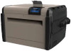
H250FDN Parts
Related Manual Pages


Related Videos

$3149 Hayward H250FDN Cost in Canada Visit www.poolproductscanada.ca
Duration: :58
Total Views: 16
Duration: :58
Total Views: 16
Similar Questions

Replacement Part Purchase
How do I order a needed part. Ref# 6 SPX1485C Gasket
How do I order a needed part. Ref# 6 SPX1485C Gasket
(Posted by raybrown76543 9 months ago)

How Do I Replace Manual Relief Valve? I Have The New Part.
My hayward xstream cartridge filter is leaking. the relief valve is dripping or sucking air when pum...
My hayward xstream cartridge filter is leaking. the relief valve is dripping or sucking air when pum...
(Posted by dalerbrown 11 years ago)

Interlock Switch Part No Idx Ils 1930 Please
Where can I buy this part ASAP?
Where can I buy this part ASAP?
(Posted by daniloarias 12 years ago)