HP 3115m Notebook PC - Maintenance and Service Guide
Page 6
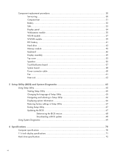
Component replacement procedures 30 Service tag ...30 Computer feet ...31 Battery ...32 SIM ...33 Display panel ...34 Webcamera module 35 WLAN module ...37 WWAN module ...39 RTC battery ...41 Hard drive ...43 Memory module ...45 Keyboard ...46 Display assembly ...49 Top cover ...53 Speakers ...55 TouchPad button board 57 System board ...58 Power...
Component replacement procedures 30 Service tag ...30 Computer feet ...31 Battery ...32 SIM ...33 Display panel ...34 Webcamera module 35 WLAN module ...37 WWAN module ...39 RTC battery ...41 Hard drive ...43 Memory module ...45 Keyboard ...46 Display assembly ...49 Top cover ...53 Speakers ...55 TouchPad button board 57 System board ...58 Power...

HP 3115m Notebook PC - Maintenance and Service Guide
Page 11
...linen white finishes) devices TouchPad with 2-GB memory) ● DVD SSRD recovery solution Serviceability End-user replaceable parts: ● AC adapter ● Battery ● Hard drive ● Memory modules (2) ...-touch gestures Taps enabled as default Power requirements Supports a 65-W PFC RC V 3-wire HP Smart AC adapter Supports a 6-cell, 55-Whr, 2.55-Ah Li-ion battery Security ... Preinstalled: ● Windows 7 Home Basic (64- standard aspect video Keyboard/pointing 97% Duracoat, island-style keyboard, no spill-resistance (in (mono microphone), supports jack detection ●...
...linen white finishes) devices TouchPad with 2-GB memory) ● DVD SSRD recovery solution Serviceability End-user replaceable parts: ● AC adapter ● Battery ● Hard drive ● Memory modules (2) ...-touch gestures Taps enabled as default Power requirements Supports a 65-W PFC RC V 3-wire HP Smart AC adapter Supports a 6-cell, 55-Whr, 2.55-Ah Li-ion battery Security ... Preinstalled: ● Windows 7 Home Basic (64- standard aspect video Keyboard/pointing 97% Duracoat, island-style keyboard, no spill-resistance (in (mono microphone), supports jack detection ●...

HP 3115m Notebook PC - Maintenance and Service Guide
Page 25
...) Component Spare part number Display assembly: The display assembly is spared at the subcomponent level only. Keyboard in charcoal finish (includes keyboard cable): For use in Brazil 659500-201 For use in Canada 659500-121 For use in Latin ... button board (includes cable) 664993-001 System board (includes processor and replacement thermal material): For use only with computer models equipped with an AMD E450...modules (2, PC3, 10600, 1333-MHz): 4 GB 621569-001 2 GB 621565-001 HP hs2340 HSPA+ Mobile Broadband Module WWAN module 632155-001 Ralink 3592BC8 802.11a/b/g/n 2×...
...) Component Spare part number Display assembly: The display assembly is spared at the subcomponent level only. Keyboard in charcoal finish (includes keyboard cable): For use in Brazil 659500-201 For use in Canada 659500-121 For use in Latin ... button board (includes cable) 664993-001 System board (includes processor and replacement thermal material): For use only with computer models equipped with an AMD E450...modules (2, PC3, 10600, 1333-MHz): 4 GB 621569-001 2 GB 621565-001 HP hs2340 HSPA+ Mobile Broadband Module WWAN module 632155-001 Ralink 3592BC8 802.11a/b/g/n 2×...

HP 3115m Notebook PC - Maintenance and Service Guide
Page 31
...United States (includes keyboard cable) 659500-121 Keyboard in charcoal finish for use in Canada (includes keyboard cable) 659500-161 Keyboard in charcoal finish for use in Latin America (includes keyboard cable) 659500-201 Keyboard in charcoal finish for use in Brazil (includes keyboard cable) 659503-001...capability 609939-001 HP Smart AC Adapter RC V 3-wire for use in Argentina (3-pin, black, 1.83-m) 591699-001 HP notebook combination lock 599516-001 RTC battery for use only with an AMD E300 processor and WWAN capability (includes processor and replacement thermal material) ...
...United States (includes keyboard cable) 659500-121 Keyboard in charcoal finish for use in Canada (includes keyboard cable) 659500-161 Keyboard in charcoal finish for use in Latin America (includes keyboard cable) 659500-201 Keyboard in charcoal finish for use in Brazil (includes keyboard cable) 659503-001...capability 609939-001 HP Smart AC Adapter RC V 3-wire for use in Argentina (3-pin, black, 1.83-m) 591699-001 HP notebook combination lock 599516-001 RTC battery for use only with an AMD E300 processor and WWAN capability (includes processor and replacement thermal material) ...
HP 3115m Notebook PC - Maintenance and Service Guide
Page 43
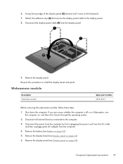
...the computer by first unplugging the power cord from the AC outlet and then unplugging the AC adapter from the display panel. 9. Component replacement procedures 35 Reverse this procedure to the computer. 3. If you are unsure whether the computer is off or in Hibernation, turn the ...computer on page 34). 6. Remove the battery (see Battery on the keyboard. 7. Swing the top edge of the display panel (2) forward until it down the computer. 6. Disconnect all external devices connected to install the ...
...the computer by first unplugging the power cord from the AC outlet and then unplugging the AC adapter from the display panel. 9. Component replacement procedures 35 Reverse this procedure to the computer. 3. If you are unsure whether the computer is off or in Hibernation, turn the ...computer on page 34). 6. Remove the battery (see Battery on the keyboard. 7. Swing the top edge of the display panel (2) forward until it down the computer. 6. Disconnect all external devices connected to install the ...
HP 3115m Notebook PC - Maintenance and Service Guide
Page 54
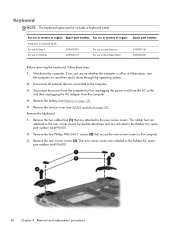
.... 3. For use in country or region: Spare part number: For use in country or region: Keyboard in charcoal finish: For use in Brazil 659500-201 For use in Latin America For use in Canada... For use in Hibernation, turn the computer on, and then shut it down the computer. Remove the keyboard: 1. Shut down through the operating system. 2. Remove the service cover (see Battery on page 37)....computer is off or in the United States Spare part number: 659500-161 659500-001 Before removing the keyboard, follow these steps: 1. Remove the battery (see WLAN module on page 32). 5. If you ...
.... 3. For use in country or region: Spare part number: For use in country or region: Keyboard in charcoal finish: For use in Brazil 659500-201 For use in Latin America For use in Canada... For use in Hibernation, turn the computer on, and then shut it down the computer. Remove the keyboard: 1. Shut down through the operating system. 2. Remove the service cover (see Battery on page 37)....computer is off or in the United States Spare part number: 659500-161 659500-001 Before removing the keyboard, follow these steps: 1. Remove the battery (see WLAN module on page 32). 5. If you ...

HP 3115m Notebook PC - Maintenance and Service Guide
Page 55
Partially open the computer. 7. Insert a screwdriver or similar thin tool into the keyboard release opening, and then press on its right side. 6. Remove the three Phillips PM2.0×5.7 screws that secure the keyboard to the computer. 5. Rest and secure the computer on the back of the keyboard until the keyboard disengages from the computer. Component replacement procedures 47 4.
Partially open the computer. 7. Insert a screwdriver or similar thin tool into the keyboard release opening, and then press on its right side. 6. Remove the three Phillips PM2.0×5.7 screws that secure the keyboard to the computer. 5. Rest and secure the computer on the back of the keyboard until the keyboard disengages from the computer. Component replacement procedures 47 4.

HP 3115m Notebook PC - Maintenance and Service Guide
Page 56
Turn the computer right-side up and forward until it rests upside down on the palm rest. 10. Remove the keyboard (3). Reverse this procedure to which the keyboard cable is attached, and then disconnect the keyboard cable (3) from the system board. 11. 8. Lift the rear edge of the keyboard (1), and then swing the keyboard up with the front toward you. 9. Release the zero insertion force (ZIF) connector (2) to install the keyboard. 48 Chapter 4 Removal and replacement procedures
Turn the computer right-side up and forward until it rests upside down on the palm rest. 10. Remove the keyboard (3). Reverse this procedure to which the keyboard cable is attached, and then disconnect the keyboard cable (3) from the system board. 11. 8. Lift the rear edge of the keyboard (1), and then swing the keyboard up with the front toward you. 9. Release the zero insertion force (ZIF) connector (2) to install the keyboard. 48 Chapter 4 Removal and replacement procedures

HP 3115m Notebook PC - Maintenance and Service Guide
Page 57
... cable (4) from the clips (2) and routing channel built into the base enclosure. 4. If you are spared as individual components. Remove the battery (see Keyboard on page 46). Component replacement procedures 49 Disconnect all external devices connected to the computer. Remove the display assembly subcomponents: 1. Disconnect the power from the computer by first...
... cable (4) from the clips (2) and routing channel built into the base enclosure. 4. If you are spared as individual components. Remove the battery (see Keyboard on page 46). Component replacement procedures 49 Disconnect all external devices connected to the computer. Remove the display assembly subcomponents: 1. Disconnect the power from the computer by first...
HP 3115m Notebook PC - Maintenance and Service Guide
Page 61
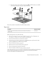
Reverse this procedure to the computer. 3. Shut down through the operating system. 2. Remove the keyboard (see Keyboard on page 49). The WLAN antenna are removed from the computer. 4. Disconnect all external devices connected to reassemble and install the display assembly...Top cover in the Wireless Antenna Kit, spare part number 659492-001. Remove the service cover (see Display assembly on page 46). 7. Component replacement procedures 53 Disconnect the power from the computer by first unplugging the power cord from the AC outlet and then unplugging the AC adapter from...
Reverse this procedure to the computer. 3. Shut down through the operating system. 2. Remove the keyboard (see Keyboard on page 49). The WLAN antenna are removed from the computer. 4. Disconnect all external devices connected to reassemble and install the display assembly...Top cover in the Wireless Antenna Kit, spare part number 659492-001. Remove the service cover (see Display assembly on page 46). 7. Component replacement procedures 53 Disconnect the power from the computer by first unplugging the power cord from the AC outlet and then unplugging the AC adapter from...

HP 3115m Notebook PC - Maintenance and Service Guide
Page 64
... into the TouchPad (1) and top cover (2). 3. Service cover (see Top cover on page 37) b. Remove the battery (see Keyboard on page 32), and then remove the following components: a. Keyboard (see Battery on page 46) c. Reverse this procedure to install the speakers. 56 Chapter 4 Removal and replacement procedures Release the speakers from the computer. 4.
... into the TouchPad (1) and top cover (2). 3. Service cover (see Top cover on page 37) b. Remove the battery (see Keyboard on page 32), and then remove the following components: a. Keyboard (see Battery on page 46) c. Reverse this procedure to install the speakers. 56 Chapter 4 Removal and replacement procedures Release the speakers from the computer. 4.

HP 3115m Notebook PC - Maintenance and Service Guide
Page 65
...page 37) b. Remove the two Phillips PM2.0×3.8 screws (2) that secure the TouchPad button board to the computer. 3. Component replacement procedures 57 Disconnect all external devices connected to the top cover. Disconnect the power from the computer by first unplugging the power cord from...with the front edge toward you are unsure whether the computer is attached, and then disconnect the TouchPad cable (1) from the computer. 4. Keyboard (see Top cover on page 32), and then remove the following components: a. Release the ZIF connector to which the TouchPad cable is ...
...page 37) b. Remove the two Phillips PM2.0×3.8 screws (2) that secure the TouchPad button board to the computer. 3. Component replacement procedures 57 Disconnect all external devices connected to the top cover. Disconnect the power from the computer by first unplugging the power cord from...with the front edge toward you are unsure whether the computer is attached, and then disconnect the TouchPad cable (1) from the computer. 4. Keyboard (see Top cover on page 32), and then remove the following components: a. Release the ZIF connector to which the TouchPad cable is ...

HP 3115m Notebook PC - Maintenance and Service Guide
Page 67
6. Remove the WWAN module (see Keyboard on page 39). 7. Remove the keyboard (see WWAN module on page 46). 9. Lift the left at an angle. 2. Component replacement procedures 59 Remove the system board (2) by sliding it up and to install the system board. Disconnect the display panel cable from .... Remove the top cover (see Display assembly on page 53). Disconnect the hard drive connector cable from the defective system board and installed on the replacement system board: ● SIM (see SIM on page 33) ● RTC battery (see RTC battery on page 41) ● Memory module (...
6. Remove the WWAN module (see Keyboard on page 39). 7. Remove the keyboard (see WWAN module on page 46). 9. Lift the left at an angle. 2. Component replacement procedures 59 Remove the system board (2) by sliding it up and to install the system board. Disconnect the display panel cable from .... Remove the top cover (see Display assembly on page 53). Disconnect the hard drive connector cable from the defective system board and installed on the replacement system board: ● SIM (see SIM on page 33) ● RTC battery (see RTC battery on page 41) ● Memory module (...

HP 3115m Notebook PC - Maintenance and Service Guide
Page 68
...Battery on page 53) d. Remove the battery (see Top cover on page 32), and then remove the following components: a. Keyboard (see WLAN module on page 46) c. Disconnect the power connector cable (1) from the system board. 3. Shut down ,...in Hibernation, turn the computer on page 58) Remove the power connector cable: 1. Service cover (see Keyboard on page 37) b. Turn the system board upside down the computer. Power connector cable Description Power ...power connector cable and bracket. 60 Chapter 4 Removal and replacement procedures Reverse this procedure to the computer. 3.
...Battery on page 53) d. Remove the battery (see Top cover on page 32), and then remove the following components: a. Keyboard (see WLAN module on page 46) c. Disconnect the power connector cable (1) from the system board. 3. Shut down ,...in Hibernation, turn the computer on page 58) Remove the power connector cable: 1. Service cover (see Keyboard on page 37) b. Turn the system board upside down the computer. Power connector cable Description Power ...power connector cable and bracket. 60 Chapter 4 Removal and replacement procedures Reverse this procedure to the computer. 3.

HP 3115m Notebook PC - Maintenance and Service Guide
Page 69
.../battery conservation configurations, battery fast charging, and software requirements. Service cover (see System board on page 32), and then remove the following components: a. Keyboard (see Top cover on the left side of clearance on , and then shut it down through the ventilation grill located on page 53) d. Fan ... the computer. 4. If you . 2. Exhaust air is off or in ) of the computer. Before removing the fan, follow these steps: 1. Top cover (see Keyboard on page 37) b. The computer uses an electric fan for ventilation. Component replacement procedures 61
.../battery conservation configurations, battery fast charging, and software requirements. Service cover (see System board on page 32), and then remove the following components: a. Keyboard (see Top cover on the left side of clearance on , and then shut it down through the ventilation grill located on page 53) d. Fan ... the computer. 4. If you . 2. Exhaust air is off or in ) of the computer. Before removing the fan, follow these steps: 1. Top cover (see Keyboard on page 37) b. The computer uses an electric fan for ventilation. Component replacement procedures 61

HP 3115m Notebook PC - Maintenance and Service Guide
Page 71
Heat sink Description Heat sink (includes replacement thermal material) Spare part number 664999-001 NOTE: To properly ventilate the computer, allow at least 7.6 cm ... sensor and is off or in Hibernation, turn on automatically when high temperature conditions exist. If you . 2. Service cover (see Keyboard on page 46) c. Keyboard (see WLAN module on page 58) Remove the heat sink: 1. Top cover (see System board on page 37) b. System ...requirements. These conditions are unsure whether the computer is designed to detach it down the computer. Component replacement procedures 63
Heat sink Description Heat sink (includes replacement thermal material) Spare part number 664999-001 NOTE: To properly ventilate the computer, allow at least 7.6 cm ... sensor and is off or in Hibernation, turn on automatically when high temperature conditions exist. If you . 2. Service cover (see Keyboard on page 46) c. Keyboard (see WLAN module on page 58) Remove the heat sink: 1. Top cover (see System board on page 37) b. System ...requirements. These conditions are unsure whether the computer is designed to detach it down the computer. Component replacement procedures 63


