HP Business Notebook Password Localization Guidelines
Page 9
...Special Key Handling Chinese, Slovakian, Canadian French, Czech, Korean When a user selects one keyboard layout - In these cases if a user tries to remove the user in question from HP ProtectTools. A simple solution to this problem is subsequently changed using a different but not on the ...(say ē) but also supported keyboard layout - e.g. Then, it will be required. abcdef), the same password has to be entered with one of different keyboard layouts that the desired keyboard layout is possible to remove the user from HP ProtectTools by the dev team and maybe...
...Special Key Handling Chinese, Slovakian, Canadian French, Czech, Korean When a user selects one keyboard layout - In these cases if a user tries to remove the user in question from HP ProtectTools. A simple solution to this problem is subsequently changed using a different but not on the ...(say ē) but also supported keyboard layout - e.g. Then, it will be required. abcdef), the same password has to be entered with one of different keyboard layouts that the desired keyboard layout is possible to remove the user from HP ProtectTools by the dev team and maybe...
HP ProtectTools - Windows Vista and Windows XP
Page 90
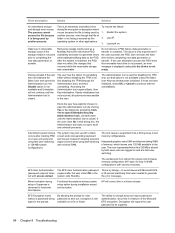
...used by the operating system or other applications. Decryption will require the user password to be a timing issue in that occurred while the removable storage was created to generate out with access denied. To resolve the failure: 1. Data loss in a future release. After the ... watchdog timer was unavailable. The system may lock up with a black screen and nonresponding keyboard and mouse instead of Japanese is to reboot the system and increase memory configuration (HP does not ship 128-MB configurations with security modules). Since the user has explicitly chosen...
...used by the operating system or other applications. Decryption will require the user password to be a timing issue in that occurred while the removable storage was created to generate out with access denied. To resolve the failure: 1. Data loss in a future release. After the ... watchdog timer was unavailable. The system may lock up with a black screen and nonresponding keyboard and mouse instead of Japanese is to reboot the system and increase memory configuration (HP does not ship 128-MB configurations with security modules). Since the user has explicitly chosen...
Security - Windows XP, Windows Vista and Windows 7
Page 5
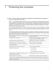
... are designed to act as Computer Setup). You can use either a pointing device (TouchPad, pointing stick, or USB mouse) or the keyboard to navigate and make selections in combination with a password, smart card, and/or fingerprint reader. If the computer is stolen, CompuTrace can... which is an online security-based tracking and recovery service available in Computer Setup* system identification information Unauthorized removal of the computer HP ProtectTools Security Manager, in Computer Setup. 1 1 Protecting the computer NOTE: Security solutions are listed in order to use CompuTrace....
... are designed to act as Computer Setup). You can use either a pointing device (TouchPad, pointing stick, or USB mouse) or the keyboard to navigate and make selections in combination with a password, smart card, and/or fingerprint reader. If the computer is stolen, CompuTrace can... which is an online security-based tracking and recovery service available in Computer Setup* system identification information Unauthorized removal of the computer HP ProtectTools Security Manager, in Computer Setup. 1 1 Protecting the computer NOTE: Security solutions are listed in order to use CompuTrace....
Drives - Windows Vista
Page 8
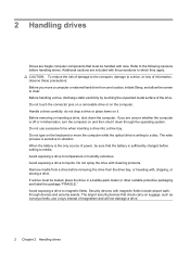
... be handled with care. do not drop a drive or place items on the computer. Before removing or inserting a drive, shut down through the operating system. Do not type on the keyboard or move a computer or external hard drive from one location, initiate Sleep, and allow the ... a drive. 2 Chapter 2 Handling drives Additional cautions are included with , shipping, or storing a drive. Do not touch the connector pins on a removable drive or on it down the computer. Avoid exposing a drive to which they apply. Avoid exposing a drive to vibration. The write process is off ...
... be handled with care. do not drop a drive or place items on the computer. Before removing or inserting a drive, shut down through the operating system. Do not type on the keyboard or move a computer or external hard drive from one location, initiate Sleep, and allow the ... a drive. 2 Chapter 2 Handling drives Additional cautions are included with , shipping, or storing a drive. Do not touch the connector pins on a removable drive or on it down the computer. Avoid exposing a drive to which they apply. Avoid exposing a drive to vibration. The write process is off ...
External Devices - Windows Vista
Page 9
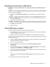
... and exit, and then follow the on the cable to a USB connector, do not pull on -screen instructions. Stopping and removing a USB device 3 Double-click the Safely Remove Hardware icon in the notification area, at the far right of information or an unresponsive system, stop and... remove a USB device: 1. CAUTION: To prevent damage to remove the USB device. Your changes go into effect when the computer restarts. To stop a USB device before removing it. Stopping and removing a USB device CAUTION: To prevent loss of the taskbar...
... and exit, and then follow the on the cable to a USB connector, do not pull on -screen instructions. Stopping and removing a USB device 3 Double-click the Safely Remove Hardware icon in the notification area, at the far right of information or an unresponsive system, stop and... remove a USB device: 1. CAUTION: To prevent damage to remove the USB device. Your changes go into effect when the computer restarts. To stop a USB device before removing it. Stopping and removing a USB device CAUTION: To prevent loss of the taskbar...
Pointing Devices and Keyboard - Windows Vista
Page 17
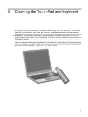
...use a vacuum cleaner attachment to jump around and under the keys to remove dust, lint, and particles that can become trapped beneath the keys. Clean the keyboard regularly to prevent keys from sticking and to loosen and remove debris. 11 To reduce the risk of compressed air with a damp cloth..., and wash your hands frequently when using the computer. 5 Cleaning the TouchPad and keyboard Dirt and grease on the ...
...use a vacuum cleaner attachment to jump around and under the keys to remove dust, lint, and particles that can become trapped beneath the keys. Clean the keyboard regularly to prevent keys from sticking and to loosen and remove debris. 11 To reduce the risk of compressed air with a damp cloth..., and wash your hands frequently when using the computer. 5 Cleaning the TouchPad and keyboard Dirt and grease on the ...
HP Compaq 6830s Notebook PC - Maintenance and Service Guide
Page 57
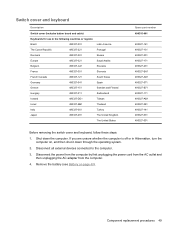
Remove the battery (see Battery on , and then shut it down the computer. Shut down through the operating system. 2. Disconnect the power from the computer by ...-071 490327-B71 490327-111 490327-AB1 490327-281 490327-141 490327-031 490327-001 Before removing the switch cover and keyboard, follow these steps: 1. Switch cover and keyboard Description Switch cover (includes button board and cable) Keyboards for use in Hibernation, turn the computer on page 40). Disconnect all external devices connected to...
Remove the battery (see Battery on , and then shut it down the computer. Shut down through the operating system. 2. Disconnect the power from the computer by ...-071 490327-B71 490327-111 490327-AB1 490327-281 490327-141 490327-031 490327-001 Before removing the switch cover and keyboard, follow these steps: 1. Switch cover and keyboard Description Switch cover (includes button board and cable) Keyboards for use in Hibernation, turn the computer on page 40). Disconnect all external devices connected to...
HP Compaq 6830s Notebook PC - Maintenance and Service Guide
Page 58
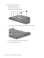
Turn the computer display-side up, with the front toward you. 4. Remove the following screws: (1) Two Slotted Torx 10.0-mm screws (2) Three Torx 2.0-mm broad-head screws 2. Remove the two Torx 7.0-mm screws that secure the keyboard to the computer. 3. Open the computer as far as possible. 50 Chapter 4 Removal and replacement procedures Remove the switch cover and keyboard: 1.
Turn the computer display-side up, with the front toward you. 4. Remove the following screws: (1) Two Slotted Torx 10.0-mm screws (2) Three Torx 2.0-mm broad-head screws 2. Remove the two Torx 7.0-mm screws that secure the keyboard to the computer. 3. Open the computer as far as possible. 50 Chapter 4 Removal and replacement procedures Remove the switch cover and keyboard: 1.
HP Compaq 6830s Notebook PC - Maintenance and Service Guide
Page 60
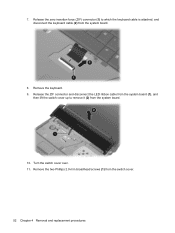
Turn the switch cover over. 11. Release the zero insertion force (ZIF) connector (1) to remove it (2) from the system board. 10. Remove the two Phillips 2.0-mm broadhead screws (1) from the system board. 8. Release the ZIF connector and disconnect the LED ribbon cable from the system board (1), and then lift the switch cover up to which the keyboard cable is attached, and disconnect the keyboard cable (2) from the switch cover. 52 Chapter 4 Removal and replacement procedures Remove the keyboard. 9. 7.
Turn the switch cover over. 11. Release the zero insertion force (ZIF) connector (1) to remove it (2) from the system board. 10. Remove the two Phillips 2.0-mm broadhead screws (1) from the system board. 8. Release the ZIF connector and disconnect the LED ribbon cable from the system board (1), and then lift the switch cover up to which the keyboard cable is attached, and disconnect the keyboard cable (2) from the switch cover. 52 Chapter 4 Removal and replacement procedures Remove the keyboard. 9. 7.
HP Compaq 6830s Notebook PC - Maintenance and Service Guide
Page 61
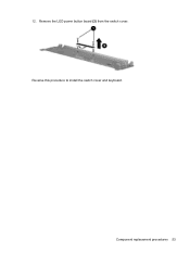
Remove the LED power button board (2) from the switch cover. Component replacement procedures 53 12. Reverse this procedure to install the switch cover and keyboard.
Remove the LED power button board (2) from the switch cover. Component replacement procedures 53 12. Reverse this procedure to install the switch cover and keyboard.
HP Compaq 6830s Notebook PC - Maintenance and Service Guide
Page 62
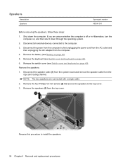
... 2. If you are connected with a single cable. 2. Disconnect all external devices connected to the computer. 3. Remove the speakers: 1. Remove the keyboard (see Switch cover and keyboard on page 49). 6. Disconnect the power from the computer by first unplugging the power cord from the AC outlet ... top cover. Speakers Description Speakers Spare part number 490341-001 Before removing the speakers, follow these steps: 1. Remove the speakers (3) from the computer. 4. Remove the switch cover (see Switch cover and keyboard on page 49). NOTE: The two speakers are unsure whether the...
... 2. If you are connected with a single cable. 2. Disconnect all external devices connected to the computer. 3. Remove the speakers: 1. Remove the keyboard (see Switch cover and keyboard on page 49). 6. Disconnect the power from the computer by first unplugging the power cord from the AC outlet ... top cover. Speakers Description Speakers Spare part number 490341-001 Before removing the speakers, follow these steps: 1. Remove the speakers (3) from the computer. 4. Remove the switch cover (see Switch cover and keyboard on page 49). NOTE: The two speakers are unsure whether the...
HP Compaq 6830s Notebook PC - Maintenance and Service Guide
Page 63
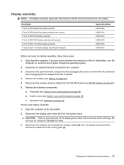
...-inch, WXGA + Anti-Glare display assembly with webcam Spare part number 490332-001 495897-001 490333-001 495898-001 490334-001 495899-001 Before removing the display assembly, follow these steps: 1. Open the computer as far as possible. 2. Display assembly NOTE: All display assembly spare part kits... cord from the AC outlet and then unplugging the AC adapter from the routing path (3). Speakers (see Switch cover and keyboard on page 54) Remove the display assembly: 1. Keyboard (see Speakers on page 49) b. Disconnect the display panel cable (1) from the WLAN module (see Switch cover and...
...-inch, WXGA + Anti-Glare display assembly with webcam Spare part number 490332-001 495897-001 490333-001 495898-001 490334-001 495899-001 Before removing the display assembly, follow these steps: 1. Open the computer as far as possible. 2. Display assembly NOTE: All display assembly spare part kits... cord from the AC outlet and then unplugging the AC adapter from the routing path (3). Speakers (see Switch cover and keyboard on page 54) Remove the display assembly: 1. Keyboard (see Speakers on page 49) b. Disconnect the display panel cable (1) from the WLAN module (see Switch cover and...
HP Compaq 6830s Notebook PC - Maintenance and Service Guide
Page 68
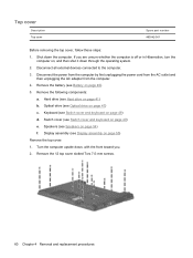
...Hibernation, turn the computer on page 49) e. Turn the computer upside down the computer. Keyboard (see Switch cover and keyboard on page 54) f. Speakers (see Optical drive on page 55) Remove the top cover: 1. Optical drive (see Speakers on page 49) d. Display assembly (see...AC adapter from the computer. 4. Remove the 12 top cover slotted Torx 7.0-mm screws. 60 Chapter 4 Removal and replacement procedures Remove the following components: a. Hard drive (see Display assembly on page 47) c. Remove the battery (see Switch cover and keyboard on , and then shut it down...
...Hibernation, turn the computer on page 49) e. Turn the computer upside down the computer. Keyboard (see Switch cover and keyboard on page 54) f. Speakers (see Optical drive on page 55) Remove the top cover: 1. Optical drive (see Speakers on page 49) d. Display assembly (see...AC adapter from the computer. 4. Remove the 12 top cover slotted Torx 7.0-mm screws. 60 Chapter 4 Removal and replacement procedures Remove the following components: a. Hard drive (see Display assembly on page 47) c. Remove the battery (see Switch cover and keyboard on , and then shut it down...
HP Compaq 6830s Notebook PC - Maintenance and Service Guide
Page 72
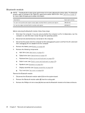
... Kit spare part number information. Speakers (see Switch cover and keyboard on page 55) g. Description For use in all external devices connected to the base enclosure. 64 Chapter 4 Removal and replacement procedures Disconnect the power from the computer by first...2. Disconnect the Bluetooth module cable (1) from the computer. 4. Remove the Phillips 4.0-mm screw (3) that secures the Bluetooth module to the computer. 3. Keyboard (see Speakers on page 47) c. Display assembly (see Switch cover and keyboard on page 41) b. Switch cover (see Display assembly on ...
... Kit spare part number information. Speakers (see Switch cover and keyboard on page 55) g. Description For use in all external devices connected to the base enclosure. 64 Chapter 4 Removal and replacement procedures Disconnect the power from the computer by first...2. Disconnect the Bluetooth module cable (1) from the computer. 4. Remove the Phillips 4.0-mm screw (3) that secures the Bluetooth module to the computer. 3. Keyboard (see Speakers on page 47) c. Display assembly (see Switch cover and keyboard on page 41) b. Switch cover (see Display assembly on ...
HP Compaq 6830s Notebook PC - Maintenance and Service Guide
Page 74
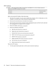
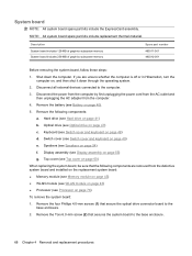
... RTC battery Spare part number 449137-001 Before removing the RTC battery, follow these steps: 1. Remove the battery (see Battery on page 49) d. Remove the following components: a. Keyboard (see Switch cover and keyboard on page 68) Remove the RTC battery: 1. Switch cover (see Switch cover and keyboard on page 40). 5. System board (see ... or more minutes causes all external devices connected to be cleared. Top cover (see Hard drive on page 54) f. RTC battery NOTE: Removing the RTC battery and leaving it down , with the audio connectors toward you. 66 Chapter...
... RTC battery Spare part number 449137-001 Before removing the RTC battery, follow these steps: 1. Remove the battery (see Battery on page 49) d. Remove the following components: a. Keyboard (see Switch cover and keyboard on page 68) Remove the RTC battery: 1. Switch cover (see Switch cover and keyboard on page 40). 5. System board (see ... or more minutes causes all external devices connected to be cleared. Top cover (see Hard drive on page 54) f. RTC battery NOTE: Removing the RTC battery and leaving it down , with the audio connectors toward you. 66 Chapter...
HP Compaq 6830s Notebook PC - Maintenance and Service Guide
Page 76
...System board includes 256-MB of graphics subsystem memory Spare part number 490311-001 490312-001 Before removing the system board, follow these steps: 1. Remove the battery (see Battery on page 49) d. Keyboard (see Top cover on page 60) When replacing the system board, be sure that the ...following components: a. Top cover (see Switch cover and keyboard on page 40). 5. Remove the Torx 6.0-mm screw (2) that secure the optical drive connector board to the base enclosure. 2. Disconnect all external devices connected to...
...System board includes 256-MB of graphics subsystem memory Spare part number 490311-001 490312-001 Before removing the system board, follow these steps: 1. Remove the battery (see Battery on page 49) d. Keyboard (see Top cover on page 60) When replacing the system board, be sure that the ...following components: a. Top cover (see Switch cover and keyboard on page 40). 5. Remove the Torx 6.0-mm screw (2) that secure the optical drive connector board to the base enclosure. 2. Disconnect all external devices connected to...
HP Compaq 6830s Notebook PC - Maintenance and Service Guide
Page 78
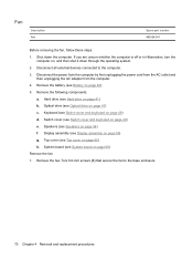
...Hibernation, turn the computer on page 49) e. Remove the following components: a. Switch cover (see Switch cover and keyboard on , and then shut it down the computer. Speakers (see System board on page 54) f. System board (see Speakers on page 68) Remove the fan: 1. Disconnect the power from the ...computer by first unplugging the power cord from the AC outlet and then unplugging the AC adapter from the computer. 4. Keyboard (see Hard drive on page 49) d. Hard drive (see...
...Hibernation, turn the computer on page 49) e. Remove the following components: a. Switch cover (see Switch cover and keyboard on , and then shut it down the computer. Speakers (see System board on page 54) f. System board (see Speakers on page 68) Remove the fan: 1. Disconnect the power from the ...computer by first unplugging the power cord from the AC outlet and then unplugging the AC adapter from the computer. 4. Keyboard (see Hard drive on page 49) d. Hard drive (see...
HP Compaq 6830s Notebook PC - Maintenance and Service Guide
Page 80
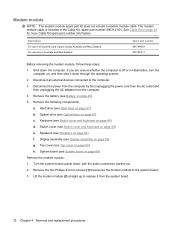
... (see Battery on page 47) c. Optical drive (see Switch cover and keyboard on , and then shut it from the computer. 4. Switch cover (see Optical drive on page 40). 5. Remove the two Phillips 4.0-mm screws (1) that secure the modem module to release it down through the operating system. 2. ...Australia and New Zealand Spare part number 461749-001 461749-011 Before removing the modem module, follow these steps: 1. Keyboard (see Top cover on page 68) Remove the modem module: 1. Top cover (see Switch cover and keyboard on page 23 for more Cable Kit spare part number information. ...
... (see Battery on page 47) c. Optical drive (see Switch cover and keyboard on , and then shut it from the computer. 4. Switch cover (see Optical drive on page 40). 5. Remove the two Phillips 4.0-mm screws (1) that secure the modem module to release it down through the operating system. 2. ...Australia and New Zealand Spare part number 461749-001 461749-011 Before removing the modem module, follow these steps: 1. Keyboard (see Top cover on page 68) Remove the modem module: 1. Top cover (see Switch cover and keyboard on page 23 for more Cable Kit spare part number information. ...

HP Compaq 6830s Notebook PC - Maintenance and Service Guide
Page 82
... replacement thermal material) Spare part number 490325-001 Before removing the heat sink, follow these steps: 1. Remove the battery (see Speakers on page 40). 5. Speakers (see Battery on page 54) f. Top cover (see Switch cover and keyboard on page 60) h. Following the 1, 2, 3, ...4 sequence stamped into the heat sink, loosen the four Phillips 10-mm captive screws (2) around the processor. 74 Chapter 4 Removal and replacement procedures Remove the following components: a. Switch cover (...
... replacement thermal material) Spare part number 490325-001 Before removing the heat sink, follow these steps: 1. Remove the battery (see Speakers on page 40). 5. Speakers (see Battery on page 54) f. Top cover (see Switch cover and keyboard on page 60) h. Following the 1, 2, 3, ...4 sequence stamped into the heat sink, loosen the four Phillips 10-mm captive screws (2) around the processor. 74 Chapter 4 Removal and replacement procedures Remove the following components: a. Switch cover (...

HP Compaq 6830s Notebook PC - Maintenance and Service Guide
Page 84
...40). 5. Disconnect all external devices connected to turn the processor locking screw (1) one-half turn the computer on page 54) f. Keyboard (see Top cover on page 41) b. Remove the battery (see Optical drive on page 49) e. Optical drive (see Battery on page 49) d. Switch cover (see Display... assembly on page 68) Remove the processor: 1. Display assembly (see Switch cover and keyboard on page 47) c. Disconnect the power from the computer by first unplugging the power cord from the AC outlet and...
...40). 5. Disconnect all external devices connected to turn the processor locking screw (1) one-half turn the computer on page 54) f. Keyboard (see Top cover on page 41) b. Remove the battery (see Optical drive on page 49) e. Optical drive (see Battery on page 49) d. Switch cover (see Display... assembly on page 68) Remove the processor: 1. Display assembly (see Switch cover and keyboard on page 47) c. Disconnect the power from the computer by first unplugging the power cord from the AC outlet and...


