Service Guide
Page 6
... module ...45 WLAN module ...47 Keyboard ...50 Top cover ...53 Fan ...55 Bluetooth module ...57 System board ...59 Speaker assembly ...63 LED board ...64 RTC battery ...66 Display assembly ...68 Webcam/microphone module 72 Power connector cable ...74 Heat sink ...76 5 Setup Utility Starting the Setup Utility ...80 Using the Setup...
... module ...45 WLAN module ...47 Keyboard ...50 Top cover ...53 Fan ...55 Bluetooth module ...57 System board ...59 Speaker assembly ...63 LED board ...64 RTC battery ...66 Display assembly ...68 Webcam/microphone module 72 Power connector cable ...74 Heat sink ...76 5 Setup Utility Starting the Setup Utility ...80 Using the Setup...

Service Guide
Page 8
Universal Serial Bus ...126 10 Power cord set requirements Requirements for all countries or regions 127 Requirements for specific countries or regions 128 11 Recycling Battery ...129 Display ...129 Index ...135 viii
Universal Serial Bus ...126 10 Power cord set requirements Requirements for all countries or regions 127 Requirements for specific countries or regions 128 11 Recycling Battery ...129 Display ...129 Index ...135 viii

Service Guide
Page 11
... TouchPad supports 2-way scrolling √ √ Taps enabled as default √ √ Power 4-cell, 40.32-Wh, 2.8-Ah Li-ion battery √ √ requirements 6-cell, 55-Wh, 2.55-Ah Li-ion battery √ √ 3 supports √ √ all worldwide standards External media Digital Media Slot √ √ card Supports Memory Stick (MS...
... TouchPad supports 2-way scrolling √ √ Taps enabled as default √ √ Power 4-cell, 40.32-Wh, 2.8-Ah Li-ion battery √ √ requirements 6-cell, 55-Wh, 2.55-Ah Li-ion battery √ √ 3 supports √ √ all worldwide standards External media Digital Media Slot √ √ card Supports Memory Stick (MS...

Service Guide
Page 12
... (32-bit) √ √ Windows Vista Home Premium (32-bit) √ √ Windows Vista Home Premium (64-bit) √ √ Serviceability AC adapter √ √ Battery (system) √ √ Hard drive (1) √ √ Memory module √ √ Mini-Card components √ √ 4 Chapter 1 Product description
... (32-bit) √ √ Windows Vista Home Premium (32-bit) √ √ Windows Vista Home Premium (64-bit) √ √ Serviceability AC adapter √ √ Battery (system) √ √ Hard drive (1) √ √ Memory module √ √ Mini-Card components √ √ 4 Chapter 1 Product description

Service Guide
Page 16
...fully charged. Blinking: The hard drive or optical drive is disabled. When the battery reaches a critical battery level, the battery light begins blinking rapidly. ● Off: If the computer is turned off when all batteries in the computer are off. ● On: The computer is on. ●...: The computer is in the Sleep state. ● Off: The computer is off or in Hibernation. ● On: A battery is charging. ● Blinking: A battery that is enabled. 8 Chapter 2 External component identification If the computer is not plugged into an external power source, the light is...
...fully charged. Blinking: The hard drive or optical drive is disabled. When the battery reaches a critical battery level, the battery light begins blinking rapidly. ● Off: If the computer is turned off when all batteries in the computer are off. ● On: The computer is on. ●...: The computer is in the Sleep state. ● Off: The computer is off or in Hibernation. ● On: A battery is charging. ● Blinking: A battery that is enabled. 8 Chapter 2 External component identification If the computer is not plugged into an external power source, the light is...

Service Guide
Page 17
... power source, the light stays off or in the Sleep state. ● Off: The computer is off until the battery reaches a low battery level. Front components 9 Front components Component (1) Speakers (2) (2) Wireless light (3) Power light (4) Battery light (5) Drive light Description Produce sound. ● On: An integrated wireless device, such as a WLAN device and/or...
... power source, the light stays off or in the Sleep state. ● Off: The computer is off until the battery reaches a low battery level. Front components 9 Front components Component (1) Speakers (2) (2) Wireless light (3) Power light (4) Battery light (5) Drive light Description Produce sound. ● On: An integrated wireless device, such as a WLAN device and/or...

Service Guide
Page 21
... (8) Bluetooth compartment (select models only) Description Holds the hard drive. Contains the memory module and WWAN module. Release the battery from the battery bay. If you replace the module and then receive a warning message, remove the module to cool internal components and prevent ...the governmental agency that regulates wireless devices in your country or region. Bottom components 13 It is located inside the battery bay. Holds the battery. NOTE: To prevent an unresponsive system, replace the wireless module only with a wireless module authorized for the internal...
... (8) Bluetooth compartment (select models only) Description Holds the hard drive. Contains the memory module and WWAN module. Release the battery from the battery bay. If you replace the module and then receive a warning message, remove the module to cool internal components and prevent ...the governmental agency that regulates wireless devices in your country or region. Bottom components 13 It is located inside the battery bay. Holds the battery. NOTE: To prevent an unresponsive system, replace the wireless module only with a wireless module authorized for the internal...
Service Guide
Page 27
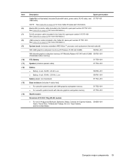
... Cable Kit, spare part number 517757-001. See Cable Kit on page 23 for more information.) System board (includes embedded AMD Athlon™ processor and replacement thermal material) With UMA graphics subsystem memory (ATI Radeon X1250 with 64MB) 506762-001 With discrete graphics ...with 512MB 506763-001 of dedicated video memory) RTC Battery 517759-001 Speaker (includes speaker cable) 517754-001 Battery ● Battery, 4-cell, 32-Wh, 2.8-Ah Li-on ● Battery, 6-cell, 55-Wh, 2.55-Ah, Li-on 506780-001 506781-001 Battery cover (not illustrated) 517744-001 Base enclosure (...
... Cable Kit, spare part number 517757-001. See Cable Kit on page 23 for more information.) System board (includes embedded AMD Athlon™ processor and replacement thermal material) With UMA graphics subsystem memory (ATI Radeon X1250 with 64MB) 506762-001 With discrete graphics ...with 512MB 506763-001 of dedicated video memory) RTC Battery 517759-001 Speaker (includes speaker cable) 517754-001 Battery ● Battery, 4-cell, 32-Wh, 2.8-Ah Li-on ● Battery, 6-cell, 55-Wh, 2.55-Ah, Li-on 506780-001 506781-001 Battery cover (not illustrated) 517744-001 Base enclosure (...

Service Guide
Page 36
...±RW SuperMulti Double-Layer Combo Drive with LightScribe External Blu-ray ROM with LightScribe DVD±R/RW SuperMulti DL Drive 4-cell Battery, 32-Wh. 2.80-Ah Li-on 6-cell Battery, 55-Wh, 2.55-Ah Li-on Espresso Black keyboard for use in the United States Espresso Black keyboard for use in...
...±RW SuperMulti Double-Layer Combo Drive with LightScribe External Blu-ray ROM with LightScribe DVD±R/RW SuperMulti DL Drive 4-cell Battery, 32-Wh. 2.80-Ah Li-on 6-cell Battery, 55-Wh, 2.55-Ah Li-on Espresso Black keyboard for use in the United States Espresso Black keyboard for use in...

Service Guide
Page 38
...517753-001 517754-001 517756-001 517757-001 517758-001 517759-001 517760-001 517761-001 517762-001 519533-001 Description Display screw kit Battery cover Top cover, Espresso Black (includes TouchPad, TouchPad cable, and TouchPad buttons) Thermal module, UMA (includes heat sink and thermal material... subsystem memory Base enclosure for use with system boards with discrete graphics subsystem memory Speaker Power switch board Cable Kit DC in cable RTC battery Antennas Rubber Kit (includes 4 base enclosure rubber feet and 2 display bezel screw covers) Screw Kit Top cover, Moonlight White (includes ...
...517753-001 517754-001 517756-001 517757-001 517758-001 517759-001 517760-001 517761-001 517762-001 519533-001 Description Display screw kit Battery cover Top cover, Espresso Black (includes TouchPad, TouchPad cable, and TouchPad buttons) Thermal module, UMA (includes heat sink and thermal material... subsystem memory Base enclosure for use with system boards with discrete graphics subsystem memory Speaker Power switch board Cable Kit DC in cable RTC battery Antennas Rubber Kit (includes 4 base enclosure rubber feet and 2 display bezel screw covers) Screw Kit Top cover, Moonlight White (includes ...

Service Guide
Page 44
...AC power to clear the password. NOTE: These steps also clear CMOS. Remove the battery (see RTC battery on page 39). 5. Shut down through the operating system. 2. Remove the RTC battery (see Battery on page 66). 6. Unknown user password If the computer you are servicing has an...devices connected to the computer. 3. Disconnect all CMOS settings have been cleared. 36 Chapter 4 Removal and replacement procedures Do not reinsert any batteries at this time. 9. Wait approximately 10 seconds. 7. Before disassembling the computer, follow these steps: 1. If you are unsure whether ...
...AC power to clear the password. NOTE: These steps also clear CMOS. Remove the battery (see RTC battery on page 39). 5. Shut down through the operating system. 2. Remove the RTC battery (see Battery on page 66). 6. Unknown user password If the computer you are servicing has an...devices connected to the computer. 3. Disconnect all CMOS settings have been cleared. 36 Chapter 4 Removal and replacement procedures Do not reinsert any batteries at this time. 9. Wait approximately 10 seconds. 7. Before disassembling the computer, follow these steps: 1. If you are unsure whether ...

Service Guide
Page 47
...Disconnect all external devices connected to the right (2) and hold it is seated. On the battery pack, slide the right battery release latch to the left (1), then slide the left battery release latch to the computer. 3. Turn the computer upside down the computer. Disconnect the power... adapter from the computer. The battery release latches automatically lock the battery into the battery bay and push in Hibernation, turn the computer on a flat surface. 2. To insert the battery, insert the rear edge of the battery into place. Slide the battery pack (3) away from the computer...
...Disconnect all external devices connected to the right (2) and hold it is seated. On the battery pack, slide the right battery release latch to the left (1), then slide the left battery release latch to the computer. 3. Turn the computer upside down the computer. Disconnect the power... adapter from the computer. The battery release latches automatically lock the battery into the battery bay and push in Hibernation, turn the computer on a flat surface. 2. To insert the battery, insert the rear edge of the battery into place. Slide the battery pack (3) away from the computer...

Service Guide
Page 48
... secure the hard drive bay cover to the computer. 3. Disconnect all external devices connected to the computer. 40 Chapter 4 Removal and replacement procedures Remove the battery (see Battery on , and then shut it down through the operating system. 2. Shut down with 506777-001 tab, and 4 rubber isolators) Before removing the hard drive...
... secure the hard drive bay cover to the computer. 3. Disconnect all external devices connected to the computer. 40 Chapter 4 Removal and replacement procedures Remove the battery (see Battery on , and then shut it down through the operating system. 2. Shut down with 506777-001 tab, and 4 rubber isolators) Before removing the hard drive...

Service Guide
Page 51
... shut it up and to release the memory module. (The edge of the module opposite the slot rises away from the computer. 4. Remove the battery (see Battery on each side of the cover, swing it down through the operating system. 2. Lift the front edge of the memory module slot to the left...
... shut it up and to release the memory module. (The edge of the module opposite the slot rises away from the computer. 4. Remove the battery (see Battery on each side of the cover, swing it down through the operating system. 2. Lift the front edge of the memory module slot to the left...
Service Guide
Page 53
... the computer on page 39). Disconnect all external devices connected to restore computer functionality, and then contact technical support through the operating system. 2. Remove the battery (see Battery on , and then shut it up and to the computer. 3. The memory module compartment cover is off or in Access doors, spare part number...
... the computer on page 39). Disconnect all external devices connected to restore computer functionality, and then contact technical support through the operating system. 2. Remove the battery (see Battery on , and then shut it up and to the computer. 3. The memory module compartment cover is off or in Access doors, spare part number...
Service Guide
Page 56
... unplugging the power cord from the AC outlet and then unplugging the AC adapter from the computer. 4. Shut down through Help and Support. 1. Remove the battery (see Battery on , and then shut it up and to restore computer functionality, and then contact technical support through the operating system. 2.
... unplugging the power cord from the AC outlet and then unplugging the AC adapter from the computer. 4. Shut down through Help and Support. 1. Remove the battery (see Battery on , and then shut it up and to restore computer functionality, and then contact technical support through the operating system. 2.

Service Guide
Page 59
... page 39). 5. Open the computer as far as possible. 5. Component replacement procedures 51 3. Remove the battery (see Hard drive on page 47) Remove the keyboard: 1. Memory module (see WLAN module on page 40) b. Turn the computer upside down with the front ...
... page 39). 5. Open the computer as far as possible. 5. Component replacement procedures 51 3. Remove the battery (see Hard drive on page 47) Remove the keyboard: 1. Memory module (see WLAN module on page 40) b. Turn the computer upside down with the front ...

Service Guide
Page 61
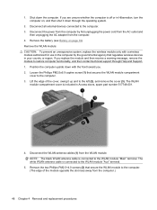
If you are unsure whether the computer is off or in Hibernation, turn the computer on page 47) e. WLAN module (see Battery on page 50) Remove the top cover: 1. Remove the battery (see WLAN module on , and then shut it down through the operating system. 2. Remove the two Phillips PM2.5x9.0 screws (1) and...
If you are unsure whether the computer is off or in Hibernation, turn the computer on page 47) e. WLAN module (see Battery on page 50) Remove the top cover: 1. Remove the battery (see WLAN module on , and then shut it down through the operating system. 2. Remove the two Phillips PM2.5x9.0 screws (1) and...

Service Guide
Page 63
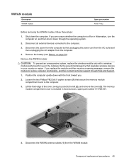
... fan: 1. Remove the three Phillips PM2.0x5.0 screws (1) that secure the fan to the computer. 3. Remove the following components: a. WWAN module (see Battery on page 45) d. Remove the battery (see WWAN module on page 39). 5. Shut down through the operating system. 2. Fan Description Fan Spare part number 517749-001 Before removing the...
... fan: 1. Remove the three Phillips PM2.0x5.0 screws (1) that secure the fan to the computer. 3. Remove the following components: a. WWAN module (see Battery on page 45) d. Remove the battery (see WWAN module on page 39). 5. Shut down through the operating system. 2. Fan Description Fan Spare part number 517749-001 Before removing the...

Service Guide
Page 64
... least a 7.6-cm (3-inch) clearance on automatically when high temperature conditions exist. The fan is controlled by high external temperatures, system power consumption, power management/battery conservation configurations, battery fast charging, and software requirements. Lift the fan (3) up from the base enclosure. Exhaust air is designed to install the fan. 3. The computer uses...
... least a 7.6-cm (3-inch) clearance on automatically when high temperature conditions exist. The fan is controlled by high external temperatures, system power consumption, power management/battery conservation configurations, battery fast charging, and software requirements. Lift the fan (3) up from the base enclosure. Exhaust air is designed to install the fan. 3. The computer uses...


