Service Guide
Page 6
... Service tag ...37 Computer feet ...38 Battery ...39 Hard drive ...40 Memory module ...43 WWAN module ...45 WLAN module ...47 Keyboard ...50 Top cover ...53 Fan ...55 Bluetooth module ...57 System board ...59 Speaker assembly ...63 LED board ...64 RTC battery ...66 Display assembly ...68 Webcam/microphone module 72 Power connector...
... Service tag ...37 Computer feet ...38 Battery ...39 Hard drive ...40 Memory module ...43 WWAN module ...45 WLAN module ...47 Keyboard ...50 Top cover ...53 Fan ...55 Bluetooth module ...57 System board ...59 Speaker assembly ...63 LED board ...64 RTC battery ...66 Display assembly ...68 Webcam/microphone module 72 Power connector...

Service Guide
Page 20
... up automatically to cycle on and off during routine operation. 12 Chapter 2 External component identification It is normal for the internal fan to cool internal components and prevent overheating. Left-side components Component (1) RJ-45 (network) jack (2) External monitor port (3) HDMI port (select models only) (4) USB ports (2) (5) ...
... up automatically to cycle on and off during routine operation. 12 Chapter 2 External component identification It is normal for the internal fan to cool internal components and prevent overheating. Left-side components Component (1) RJ-45 (network) jack (2) External monitor port (3) HDMI port (select models only) (4) USB ports (2) (5) ...

Service Guide
Page 21
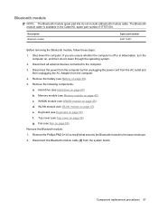
...the module to cool internal components and prevent overheating. Holds the battery. Contains a Bluetooth device. NOTE: The computer fan starts up automatically to restore computer functionality, and then contact technical support through Help and Support. Contains a subscriber identity... and WWAN module. NOTE: To prevent an unresponsive system, replace the wireless module only with a wireless module authorized for the internal fan to cool internal components. Bottom components Component (1) Hard drive bay (2) Vents (4) (3) Memory module compartment (4) SIM slot (select models...
...the module to cool internal components and prevent overheating. Holds the battery. Contains a Bluetooth device. NOTE: The computer fan starts up automatically to restore computer functionality, and then contact technical support through Help and Support. Contains a subscriber identity... and WWAN module. NOTE: To prevent an unresponsive system, replace the wireless module only with a wireless module authorized for the internal fan to cool internal components. Bottom components Component (1) Hard drive bay (2) Vents (4) (3) Memory module compartment (4) SIM slot (select models...

Service Guide
Page 26
..., TouchPad cable, and TouchPad buttons) Top cover, Espresso Black Top cover, Moonlight White Thermal module Thermal module, UMA (heat sink) Thermal module, discrete (heat sink) Fan 18 Chapter 3 Illustrated parts catalog Spare part number 506782-281 506782-141 506782-031 506782-001 517584-A41 517584-201 517584-DH1 517584-051 517584...
..., TouchPad cable, and TouchPad buttons) Top cover, Espresso Black Top cover, Moonlight White Thermal module Thermal module, UMA (heat sink) Thermal module, discrete (heat sink) Fan 18 Chapter 3 Illustrated parts catalog Spare part number 506782-281 506782-141 506782-031 506782-001 517584-A41 517584-201 517584-DH1 517584-051 517584...

Service Guide
Page 38
... (includes heat sink and thermal material) Access doors (includes digital media slot bezel, WLAN module compartment cover, memory module compartment cover, hard drive bay cover) Fan Base enclosure for use with system boards with UMA graphics subsystem memory Base enclosure for use with system boards with discrete graphics subsystem memory Speaker...
... (includes heat sink and thermal material) Access doors (includes digital media slot bezel, WLAN module compartment cover, memory module compartment cover, hard drive bay cover) Fan Base enclosure for use with system boards with UMA graphics subsystem memory Base enclosure for use with system boards with discrete graphics subsystem memory Speaker...

Service Guide
Page 63
... by first unplugging the power cord from the AC outlet and then unplugging the AC adapter from the system board. Fan Description Fan Spare part number 517749-001 Before removing the fan, follow these steps: 1. If you are unsure whether is off or in Hibernation, turn the computer on page 45...) d. Top cover (see Battery on page 53) Remove the fan: 1. Remove the battery (see Top cover on page 39). 5. Memory module (see Keyboard on page 43) c. Keyboard (see Memory module on page 50)...
... by first unplugging the power cord from the AC outlet and then unplugging the AC adapter from the system board. Fan Description Fan Spare part number 517749-001 Before removing the fan, follow these steps: 1. If you are unsure whether is off or in Hibernation, turn the computer on page 45...) d. Top cover (see Battery on page 53) Remove the fan: 1. Remove the battery (see Top cover on page 39). 5. Memory module (see Keyboard on page 43) c. Keyboard (see Memory module on page 50)...

Service Guide
Page 64
...the ventilation grill on the left side of the computer. 56 Chapter 4 Removal and replacement procedures The computer uses an electric fan for ventilation. 3. Reverse this procedure to turn on the left side of the computer. These conditions are affected by a temperature... is controlled by high external temperatures, system power consumption, power management/battery conservation configurations, battery fast charging, and software requirements. Lift the fan (3) up from the base enclosure. NOTE: To properly ventilate the computer, allow at least a 7.6-cm (3-inch) clearance on automatically when...
...the ventilation grill on the left side of the computer. 56 Chapter 4 Removal and replacement procedures The computer uses an electric fan for ventilation. 3. Reverse this procedure to turn on the left side of the computer. These conditions are affected by a temperature... is controlled by high external temperatures, system power consumption, power management/battery conservation configurations, battery fast charging, and software requirements. Lift the fan (3) up from the base enclosure. NOTE: To properly ventilate the computer, allow at least a 7.6-cm (3-inch) clearance on automatically when...
Service Guide
Page 65
...power cord from the AC outlet and then unplugging the AC Adapter from the system board. Remove the battery (see WLAN module on page 45) d. Fan (see WWAN module on page 47) e. If you are unsure whether the computer is available in Hibernation, turn the computer on page 50) f. ...WWAN module (see Fan on page 40) b. Top cover (see Hard drive on page 55) Remove the Bluetooth module: 1. Hard drive (see Top cover on page 43) c. ...
...power cord from the AC outlet and then unplugging the AC Adapter from the system board. Remove the battery (see WLAN module on page 45) d. Fan (see WWAN module on page 47) e. If you are unsure whether the computer is available in Hibernation, turn the computer on page 50) f. ...WWAN module (see Fan on page 40) b. Top cover (see Hard drive on page 55) Remove the Bluetooth module: 1. Hard drive (see Top cover on page 43) c. ...

Service Guide
Page 67
... board, be sure that the following components: a. Description Spare part number With embedded processor, MV40, 1.6-Ghz, RX781 Northbridge and ATI-M82-S discrete graphics 506763-001 subsystem memory With embedded processor, MV40, 1.6-Ghz, RS780 Northbridge and ATI-M UMA graphics subsystem memory 506762-001 Before removing the system board, follow these ... module on page 43) ● WWAN module (see WWAN module on page 45) ● WLAN module (see Bluetooth module on page 57) ● Fan (see Fan on page 55) ● Heat sink (see Battery on page 59) Component replacement procedures 59...
... board, be sure that the following components: a. Description Spare part number With embedded processor, MV40, 1.6-Ghz, RX781 Northbridge and ATI-M82-S discrete graphics 506763-001 subsystem memory With embedded processor, MV40, 1.6-Ghz, RS780 Northbridge and ATI-M UMA graphics subsystem memory 506762-001 Before removing the system board, follow these ... module on page 43) ● WWAN module (see WWAN module on page 45) ● WLAN module (see Bluetooth module on page 57) ● Fan (see Fan on page 55) ● Heat sink (see Battery on page 59) Component replacement procedures 59...

Service Guide
Page 71
... on page 43) c. Remove the following components: a. Memory module (see Memory module on , and then shut it down the computer. Fan (see System board on page 55) h. System board (see Fan on page 59) Remove the speaker assembly: 1. Disconnect all external devices connected to the base enclosure. Hard drive (see Keyboard on...
... on page 43) c. Remove the following components: a. Memory module (see Memory module on , and then shut it down the computer. Fan (see System board on page 55) h. System board (see Fan on page 59) Remove the speaker assembly: 1. Disconnect all external devices connected to the base enclosure. Hard drive (see Keyboard on...

Service Guide
Page 72
... assembly. Hard drive (see Memory module on page 40) b. Memory module (see Hard drive on page 43) c. For information on page 39). 5. Fan (see Battery on the base enclosure with a discrete heat sink, see spare part number 517752-001. If you are unsure whether the computer is included... with the base enclosure. Remove the battery (see Fan on page 50) f. WLAN module (see Keyboard on page 55) 64 Chapter 4 Removal and replacement procedures Shut down through the operating system. 2. ...
... assembly. Hard drive (see Memory module on page 40) b. Memory module (see Hard drive on page 43) c. For information on page 39). 5. Fan (see Battery on the base enclosure with a discrete heat sink, see spare part number 517752-001. If you are unsure whether the computer is included... with the base enclosure. Remove the battery (see Fan on page 50) f. WLAN module (see Keyboard on page 55) 64 Chapter 4 Removal and replacement procedures Shut down through the operating system. 2. ...

Service Guide
Page 74
... outlet and then unplugging the AC adapter from the connector on page 45) d. Remove the battery (see Battery on page 55) h. Fan (see WLAN module on page 43) c. WLAN module (see Fan on page 39). 5. Description RTC battery Spare part number 517759-001 Before removing the RTC battery, follow these steps: 1. Memory...
... outlet and then unplugging the AC adapter from the connector on page 45) d. Remove the battery (see Battery on page 55) h. Fan (see WLAN module on page 43) c. WLAN module (see Fan on page 39). 5. Description RTC battery Spare part number 517759-001 Before removing the RTC battery, follow these steps: 1. Memory...
Service Guide
Page 76
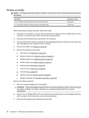
... the AC adapter from each hinge that secures the display assembly to the computer. WLAN module (see Top cover on page 47) e. Fan (see Memory module on page 55) h. Open the computer display as far as possible. Failure to support the display assembly can result in...computer on, and then shut it down the computer. Disconnect all external devices connected to the display assembly and other computer components. 2. Memory module (see Fan on page 43) c. Remove the two Phillips PM2.0×5.0 screws (1) from the computer. 4. Remove the battery (see Keyboard on page 39). 5....
... the AC adapter from each hinge that secures the display assembly to the computer. WLAN module (see Top cover on page 47) e. Fan (see Memory module on page 55) h. Open the computer display as far as possible. Failure to support the display assembly can result in...computer on, and then shut it down the computer. Disconnect all external devices connected to the display assembly and other computer components. 2. Memory module (see Fan on page 43) c. Remove the two Phillips PM2.0×5.0 screws (1) from the computer. 4. Remove the battery (see Keyboard on page 39). 5....

Service Guide
Page 82
...) h. Disconnect all external devices connected to the computer. 3. Remove the battery (see Top cover on page 47) e. f. Fan (see Hard drive on page 50). Shut down through the operating system. 2. Hard drive (see Fan on page 39). 5. Keyboard (see System board on page 59) Remove the power connector cable: 1. Disconnect the power...
...) h. Disconnect all external devices connected to the computer. 3. Remove the battery (see Top cover on page 47) e. f. Fan (see Hard drive on page 50). Shut down through the operating system. 2. Hard drive (see Fan on page 39). 5. Keyboard (see System board on page 59) Remove the power connector cable: 1. Disconnect the power...

Service Guide
Page 84
...-001 517746-001 NOTE: To properly ventilate the computer, allow at least a 7.6-cm (3-inch) clearance on page 40). The computer uses an electric fan for ventilation. The fan is controlled by high external temperatures, system power consumption, power management/battery conservation configurations, battery fast charging, and software requirements. Disconnect the power from... components: a. Hard drive (see Memory module on page 47) e. b. WWAN module (see WLAN module on page 43) c. WLAN module (see WWAN module on page 55) h. Fan (see Fan on page 45) d.
...-001 517746-001 NOTE: To properly ventilate the computer, allow at least a 7.6-cm (3-inch) clearance on page 40). The computer uses an electric fan for ventilation. The fan is controlled by high external temperatures, system power consumption, power management/battery conservation configurations, battery fast charging, and software requirements. Disconnect the power from... components: a. Hard drive (see Memory module on page 47) e. b. WWAN module (see WLAN module on page 43) c. WLAN module (see WWAN module on page 55) h. Fan (see Fan on page 45) d.
Service Guide
Page 93
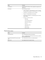
... Self Test Secondary Hard Disk Self Test (select models only) Memory Test To do this Enabled/disable Fan Always On. Setup Utility menus 85 Run a comprehensive self-test on the system memory. Select Fan Always On Boot Options To do this Run a comprehensive self-test on the hard drive. NOTE: ...On models with two hard drives, this menu option is called the Primary Hard Disk Self Test. Run a diagnostic test on a secondary hard drive. When enabled, the computer fan will always be...
... Self Test Secondary Hard Disk Self Test (select models only) Memory Test To do this Enabled/disable Fan Always On. Setup Utility menus 85 Run a comprehensive self-test on the system memory. Select Fan Always On Boot Options To do this Run a comprehensive self-test on the hard drive. NOTE: ...On models with two hard drives, this menu option is called the Primary Hard Disk Self Test. Run a diagnostic test on a secondary hard drive. When enabled, the computer fan will always be...

Service Guide
Page 114
Phillips PM2.0×5.0 screw Color Black Quantity 16 Length 5.0 mm Thread 2.0 mm Head diameter 5.0 mm Where used: 4 screws that secure the top cover to the computer Where used: 3 screws that secure the fan to the system board 106 Chapter 7 Screw listing
Phillips PM2.0×5.0 screw Color Black Quantity 16 Length 5.0 mm Thread 2.0 mm Head diameter 5.0 mm Where used: 4 screws that secure the top cover to the computer Where used: 3 screws that secure the fan to the system board 106 Chapter 7 Screw listing

Service Guide
Page 144
... cards, product description 3 external monitor port identifying 12 pin assignments 123 external optical drives, spare part numbers 24 F f11 recovery 122 fan removal 55 spare part number 18, 30, 55 fan always on 85 feet locations 38 spare part number 38 fingerprint reader 80 fn key, identifying 7 full system recovery 118 function...
... cards, product description 3 external monitor port identifying 12 pin assignments 123 external optical drives, spare part numbers 24 F f11 recovery 122 fan removal 55 spare part number 18, 30, 55 fan always on 85 feet locations 38 spare part number 38 fingerprint reader 80 fn key, identifying 7 full system recovery 118 function...


