Service Guide
Page 6
Equipment guidelines 35 Unknown user password 36 Component replacement procedures 37 Service tag ...37 Computer feet ...38 Battery ...39 Hard drive ...40 Memory module ...43 WWAN module ...45 WLAN module ...47 Keyboard ...50 Top cover ...53 Fan ...55 Bluetooth module ...57 System board ...59 Speaker assembly ...63 LED board ...64 RTC battery ...66...
Equipment guidelines 35 Unknown user password 36 Component replacement procedures 37 Service tag ...37 Computer feet ...38 Battery ...39 Hard drive ...40 Memory module ...43 WWAN module ...45 WLAN module ...47 Keyboard ...50 Top cover ...53 Fan ...55 Bluetooth module ...57 System board ...59 Speaker assembly ...63 LED board ...64 RTC battery ...66...

Service Guide
Page 58
... Turkey The United Kingdom The United States 506782-AD1 506782-071 506782-111 506782-AB1 506782-281 506782-141 506782-031 506782-001 Keyboards-Moonlight White For use in country or region Spare part number Belgium 517584-A41 Brazil 517584-201 Denmark, Norway, and Sweden France ... United States 517584-AD1 517584-071 517584-111 517584-AB1 517584-281 517584-141 517584-031 517584-001 Before removing the keyboard, follow these steps: 1. Disconnect all external devices connected to the computer. 50 Chapter 4 Removal and replacement procedures Shut down through the operating system. 2.
... Turkey The United Kingdom The United States 506782-AD1 506782-071 506782-111 506782-AB1 506782-281 506782-141 506782-031 506782-001 Keyboards-Moonlight White For use in country or region Spare part number Belgium 517584-A41 Brazil 517584-201 Denmark, Norway, and Sweden France ... United States 517584-AD1 517584-071 517584-111 517584-AB1 517584-281 517584-141 517584-031 517584-001 Before removing the keyboard, follow these steps: 1. Disconnect all external devices connected to the computer. 50 Chapter 4 Removal and replacement procedures Shut down through the operating system. 2.

Service Guide
Page 59
...Lift the rear edge of the keyboard (1) until it rests at an angle. 3. Disconnect the power from the computer. 4. Turn the computer display-side up, with the front toward you . 2. Hard drive (see WWAN module on page 39). 5. Component replacement procedures 51 Memory module (see ...Battery on page 45) d. Open the computer as far as possible. 5. Remove the battery (see Memory module on page 47) Remove the keyboard: 1. Remove one Phillips PM2.5×10.0 screw located ...
...Lift the rear edge of the keyboard (1) until it rests at an angle. 3. Disconnect the power from the computer. 4. Turn the computer display-side up, with the front toward you . 2. Hard drive (see WWAN module on page 39). 5. Component replacement procedures 51 Memory module (see ...Battery on page 45) d. Open the computer as far as possible. 5. Remove the battery (see Memory module on page 47) Remove the keyboard: 1. Remove one Phillips PM2.5×10.0 screw located ...

Service Guide
Page 60
Remove the keyboard. Reverse this procedure to which the keyboard cable is accessible. 7. Slide the keyboard (2) back until the keyboard connector on the system board is connected and disconnect the cable (2) from the system board. 8. Release the zero insertion force (ZIF) connector (1) to install the keyboard. 52 Chapter 4 Removal and replacement procedures 6.
Remove the keyboard. Reverse this procedure to which the keyboard cable is accessible. 7. Slide the keyboard (2) back until the keyboard connector on the system board is connected and disconnect the cable (2) from the system board. 8. Release the zero insertion force (ZIF) connector (1) to install the keyboard. 52 Chapter 4 Removal and replacement procedures 6.

Service Guide
Page 61
...the power from the computer by first unplugging the power cord from the AC outlet and then unplugging the AC adapter from the computer. 4. Keyboard (see WWAN module on page 50) Remove the top cover: 1. Remove the following components: a. Remove the two Phillips PM2.5x9.0 screws... (1) and the four Phillips PM2.0×5.0 screws (2) that secure the top cover to the computer. 3. Component replacement procedures 53 Top cover Description Top cover with TouchPad, TouchPad cable, and TouchPad buttons, Espresso Black Top cover with TouchPad, TouchPad cable, and ...
...the power from the computer by first unplugging the power cord from the AC outlet and then unplugging the AC adapter from the computer. 4. Keyboard (see WWAN module on page 50) Remove the top cover: 1. Remove the following components: a. Remove the two Phillips PM2.5x9.0 screws... (1) and the four Phillips PM2.0×5.0 screws (2) that secure the top cover to the computer. 3. Component replacement procedures 53 Top cover Description Top cover with TouchPad, TouchPad cable, and TouchPad buttons, Espresso Black Top cover with TouchPad, TouchPad cable, and ...

Service Guide
Page 63
Remove the following components: a. Disconnect the fan cable (2) from the computer. 4. Component replacement procedures 55 Disconnect the power from the computer by first unplugging the power cord from the AC outlet and then unplugging the AC adapter ...Phillips PM2.0x5.0 screws (1) that secure the fan to the computer. 3. Disconnect all external devices connected to the base enclosure. 2. WWAN module (see Keyboard on page 45) d. Keyboard (see WWAN module on page 50) f. Memory module (see Top cover on page 43) c. Fan Description Fan Spare part number 517749-001 Before ...
Remove the following components: a. Disconnect the fan cable (2) from the computer. 4. Component replacement procedures 55 Disconnect the power from the computer by first unplugging the power cord from the AC outlet and then unplugging the AC adapter ...Phillips PM2.0x5.0 screws (1) that secure the fan to the computer. 3. Disconnect all external devices connected to the base enclosure. 2. WWAN module (see Keyboard on page 45) d. Keyboard (see WWAN module on page 50) f. Memory module (see Top cover on page 43) c. Fan Description Fan Spare part number 517749-001 Before ...
Service Guide
Page 65
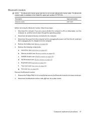
If you are unsure whether the computer is available in Hibernation, turn the computer on page 45) d. Component replacement procedures 57 Remove the following components: a. WWAN module (see Fan on page 55) Remove the Bluetooth module: 1. Fan (see WWAN ... 39). 5. Disconnect the Bluetooth module cable (2) from the computer. 4. Memory module (see Battery on page 43) c. Hard drive (see Keyboard on page 40) b. Keyboard (see Hard drive on page 50) f. Bluetooth module NOTE: The Bluetooth module spare part kits do not include a Bluetooth module cable. Description...
If you are unsure whether the computer is available in Hibernation, turn the computer on page 45) d. Component replacement procedures 57 Remove the following components: a. WWAN module (see Fan on page 55) Remove the Bluetooth module: 1. Fan (see WWAN ... 39). 5. Disconnect the Bluetooth module cable (2) from the computer. 4. Memory module (see Battery on page 43) c. Hard drive (see Keyboard on page 40) b. Keyboard (see Hard drive on page 50) f. Bluetooth module NOTE: The Bluetooth module spare part kits do not include a Bluetooth module cable. Description...

Service Guide
Page 67
...module on page 57) When replacing the system board, be sure that the following components: a. If you are removed from the computer. 4. Remove the battery (see System board on page 53) g. Hard drive (see Keyboard on page 55) h. Keyboard (see Hard drive on page...see Battery on page 40) b. Description Spare part number With embedded processor, MV40, 1.6-Ghz, RX781 Northbridge and ATI-M82-S discrete graphics 506763-001 subsystem memory With embedded processor, MV40, 1.6-Ghz, RS780 Northbridge and ATI-M UMA graphics subsystem memory 506762-001 Before removing the system board...
...module on page 57) When replacing the system board, be sure that the following components: a. If you are removed from the computer. 4. Remove the battery (see System board on page 53) g. Hard drive (see Keyboard on page 55) h. Keyboard (see Hard drive on page...see Battery on page 40) b. Description Spare part number With embedded processor, MV40, 1.6-Ghz, RX781 Northbridge and ATI-M82-S discrete graphics 506763-001 subsystem memory With embedded processor, MV40, 1.6-Ghz, RS780 Northbridge and ATI-M UMA graphics subsystem memory 506762-001 Before removing the system board...

Service Guide
Page 71
...see System board on page 39). 5. WWAN module (see Top cover on page 45) d. Top cover (see WWAN module on page 53) g. Component replacement procedures 63 Fan (see WLAN module on page 55) h. Shut down through the operating system. 2. Remove the two PM2.5x4.0 screws (1) that secure ... steps: 1. If you are unsure whether the computer is off or in Hibernation, turn the computer on page 43) c. Hard drive (see Keyboard on page 40) b. Keyboard (see Hard drive on page 50) f. Remove the following components: a. Memory module (see Memory module on , and then shut it down ...
...see System board on page 39). 5. WWAN module (see Top cover on page 45) d. Top cover (see WWAN module on page 53) g. Component replacement procedures 63 Fan (see WLAN module on page 55) h. Shut down through the operating system. 2. Remove the two PM2.5x4.0 screws (1) that secure ... steps: 1. If you are unsure whether the computer is off or in Hibernation, turn the computer on page 43) c. Hard drive (see Keyboard on page 40) b. Keyboard (see Hard drive on page 50) f. Remove the following components: a. Memory module (see Memory module on , and then shut it down ...

Service Guide
Page 72
... computer is included with the base enclosure. WLAN module (see Fan on page 55) 64 Chapter 4 Removal and replacement procedures Fan (see WLAN module on page 50) f. WWAN module (see Keyboard on page 47) e. Keyboard (see WWAN module on page 40) b. Before removing the LED board, follow these steps: 1. Remove the speaker assembly...
... computer is included with the base enclosure. WLAN module (see Fan on page 55) 64 Chapter 4 Removal and replacement procedures Fan (see WLAN module on page 50) f. WWAN module (see Keyboard on page 47) e. Keyboard (see WWAN module on page 40) b. Before removing the LED board, follow these steps: 1. Remove the speaker assembly...

Service Guide
Page 74
...see Top cover on page 45) d. Disconnect the RTC battery cable (1) from the computer. 4. WLAN module (see Keyboard on page 47) e. Keyboard (see WLAN module on page 50) f. Description RTC battery Spare part number 517759-001 Before removing the RTC battery..., follow these steps: 1. Memory module (see Fan on page 43) c. Fan (see Memory module on page 55) h. System board (see Battery on the system board. 66 Chapter 4 Removal and replacement...
...see Top cover on page 45) d. Disconnect the RTC battery cable (1) from the computer. 4. WLAN module (see Keyboard on page 47) e. Keyboard (see WLAN module on page 50) f. Description RTC battery Spare part number 517759-001 Before removing the RTC battery..., follow these steps: 1. Memory module (see Fan on page 43) c. Fan (see Memory module on page 55) h. System board (see Battery on the system board. 66 Chapter 4 Removal and replacement...
Service Guide
Page 76
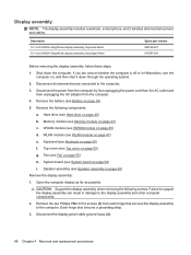
... Hard drive (see WLAN module on page 40) b. WLAN module (see Hard drive on page 47) e. Speaker assembly (see Keyboard on page 63) Remove the display assembly: 1. Display assembly NOTE: The display assembly includes a webcam, a microphone, and 2 wireless antenna transceivers ...2. Remove the two Phillips PM2.0×5.0 screws (1) from the computer. 4. Disconnect the display panel cable ground loops (2). 68 Chapter 4 Removal and replacement procedures Remove the following screws. Memory module (see Battery on page 43) c. System board (see Fan on page 59) i. Each hinge also ...
... Hard drive (see WLAN module on page 40) b. WLAN module (see Hard drive on page 47) e. Speaker assembly (see Keyboard on page 63) Remove the display assembly: 1. Display assembly NOTE: The display assembly includes a webcam, a microphone, and 2 wireless antenna transceivers ...2. Remove the two Phillips PM2.0×5.0 screws (1) from the computer. 4. Disconnect the display panel cable ground loops (2). 68 Chapter 4 Removal and replacement procedures Remove the following screws. Memory module (see Battery on page 43) c. System board (see Fan on page 59) i. Each hinge also ...

Service Guide
Page 82
Shut down through the operating system. 2. Disconnect all external devices connected to the computer. 3. Keyboard (see Hard drive on page 40). Hard drive (see Keyboard on page 50). WWAN module (see Top cover on page 53) g. Top cover (see WWAN module on page 45) d. Remove the battery (see System board ... the power cord from the AC outlet and then unplugging the AC Adapter from the clip built into the base enclosure. 74 Chapter 4 Removal and replacement procedures f. Remove the following components: a.
Shut down through the operating system. 2. Disconnect all external devices connected to the computer. 3. Keyboard (see Hard drive on page 40). Hard drive (see Keyboard on page 50). WWAN module (see Top cover on page 53) g. Top cover (see WWAN module on page 45) d. Remove the battery (see System board ... the power cord from the AC outlet and then unplugging the AC Adapter from the clip built into the base enclosure. 74 Chapter 4 Removal and replacement procedures f. Remove the following components: a.

Service Guide
Page 84
...System board on the right side and rear panel of the computer. Remove the heat sink: 76 Chapter 4 Removal and replacement procedures Description For use only with computer models equipped with discrete graphics subsystem memory For use only with computer models equipped ... temperatures, system power consumption, power management/battery conservation configurations, battery fast charging, and software requirements. Bluetooth module (see Keyboard on page 45) d. Keyboard (see Bluetooth module on page 59) j. The computer uses an electric fan for ventilation. WWAN module (see Hard...
...System board on the right side and rear panel of the computer. Remove the heat sink: 76 Chapter 4 Removal and replacement procedures Description For use only with computer models equipped with discrete graphics subsystem memory For use only with computer models equipped ... temperatures, system power consumption, power management/battery conservation configurations, battery fast charging, and software requirements. Bluetooth module (see Keyboard on page 45) d. Keyboard (see Bluetooth module on page 59) j. The computer uses an electric fan for ventilation. WWAN module (see Hard...

Service Guide
Page 145
...C6 State 84 processor, product description 1 product description audio 2 chipset 1 display panel 1 docking support 3 Ethernet 2 external media cards 3 graphics 1 hard drives 2 keyboard 3 memory module 1 microphone 2 modem 2 operating system 4 optical drives 2 pointing device 3 ports 3 power requirements 3 processor 1 product name 1 security 4 serviceability ... discs 122 recovery discs 118, 122 Recovery Manager 118 recovery partition 118, 122 recovery, system 118 removal/replacement preliminaries 31 procedures 37 restore points 120 restoring default settings 82 RJ-45 cable, illustrated 23 RJ-45 ...
...C6 State 84 processor, product description 1 product description audio 2 chipset 1 display panel 1 docking support 3 Ethernet 2 external media cards 3 graphics 1 hard drives 2 keyboard 3 memory module 1 microphone 2 modem 2 operating system 4 optical drives 2 pointing device 3 ports 3 power requirements 3 processor 1 product name 1 security 4 serviceability ... discs 122 recovery discs 118, 122 Recovery Manager 118 recovery partition 118, 122 recovery, system 118 removal/replacement preliminaries 31 procedures 37 restore points 120 restoring default settings 82 RJ-45 cable, illustrated 23 RJ-45 ...


