

User Manual
Page 7
... Twisted-Pair Cabling 4-10 Testing Switch-to-Device Network Communications 4-10 Testing End-to-End Network Communications 4-10 Restoring the Factory Default Configuration 4-11 Downloading New Switch Software 4-12 HP Customer Support Services 4-12 Before Calling Support 4-12 A Switch Specifications Physical A-1 Electrical A-1 Environmental A-2 Acoustic A-2 Connectors A-2 Cable Length A-3 Safety A-3 Lasers A-3 B Switch Ports and Network Cables Switch Ports B-1 Twisted-Pair Cables B-1 Fiber-Optic Cables B-2 Mode Conditioning Patch Cord for Gigabit-LX B-3 Installing the Patch...
... Twisted-Pair Cabling 4-10 Testing Switch-to-Device Network Communications 4-10 Testing End-to-End Network Communications 4-10 Restoring the Factory Default Configuration 4-11 Downloading New Switch Software 4-12 HP Customer Support Services 4-12 Before Calling Support 4-12 A Switch Specifications Physical A-1 Electrical A-1 Environmental A-2 Acoustic A-2 Connectors A-2 Cable Length A-3 Safety A-3 Lasers A-3 B Switch Ports and Network Cables Switch Ports B-1 Twisted-Pair Cables B-1 Fiber-Optic Cables B-2 Mode Conditioning Patch Cord for Gigabit-LX B-3 Installing the Patch...
User Manual
Page 9
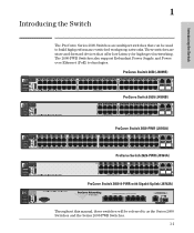
..., Gig-T ports are IEEE Auto MDI/MDI-X) 48 ! Use only one (T or M) for each Gigabit port Power Fault ProCurve Switch 2600-PWR J8762A PoE Status RPS Act EPS LED Mode FDx Fan Spd * Test PoE Reset Clear *Spd mode: off = 10 Mbps, flash = 100 Mbps, on = 1000 Mbps Console ProCurve Switch 2600-8-PWR with Gigabit Uplink (J8762A) PoE-Integrated 10/100-TX Ports (1 - 8) — (Ports are store-and-forward devices that can be referred to build high-performance switched workgroup networks.
..., Gig-T ports are IEEE Auto MDI/MDI-X) 48 ! Use only one (T or M) for each Gigabit port Power Fault ProCurve Switch 2600-PWR J8762A PoE Status RPS Act EPS LED Mode FDx Fan Spd * Test PoE Reset Clear *Spd mode: off = 10 Mbps, flash = 100 Mbps, on = 1000 Mbps Console ProCurve Switch 2600-8-PWR with Gigabit Uplink (J8762A) PoE-Integrated 10/100-TX Ports (1 - 8) — (Ports are store-and-forward devices that can be referred to build high-performance switched workgroup networks.

User Manual
Page 12
... switch ports, the fan, or the RPS or EPS operation of the Switch Network Ports ■ 8, 24, or 48 auto-sensing 10/100Base-TX ports. A fault has occurred on or reset, at the beginning of LEDs: ■ switch status LEDs (Table 1-1) ■ port LEDs (Table 1-2) ■ Port LED View (non-PWR switches) and LED Mode (PWR switches) indicator LEDs (near the selector button) (Table 1-3) Table 1-1. You can use either straight-through or crossover twisted-pair cables to connect any network devices to the switch...
... switch ports, the fan, or the RPS or EPS operation of the Switch Network Ports ■ 8, 24, or 48 auto-sensing 10/100Base-TX ports. A fault has occurred on or reset, at the beginning of LEDs: ■ switch status LEDs (Table 1-1) ■ port LEDs (Table 1-2) ■ Port LED View (non-PWR switches) and LED Mode (PWR switches) indicator LEDs (near the selector button) (Table 1-3) Table 1-1. You can use either straight-through or crossover twisted-pair cables to connect any network devices to the switch...

User Manual
Page 14
... disabled through the switch console, the web browser interface, ProCurve Manager, or other network management tool. Table 1-2. Mode Depending on the mode selected, displays the following: network activity information, whether the port is enabled and receiving a link beat signal (for the twisted-pair ports), of the Switch Port LEDs The port LEDs provide information about the individual switch ports. To clearly indicate that the mini-GBIC/SFP port has taken control of the connection depending on the Port LED View selected. See "Port LED View...
... disabled through the switch console, the web browser interface, ProCurve Manager, or other network management tool. Table 1-2. Mode Depending on the mode selected, displays the following: network activity information, whether the port is enabled and receiving a link beat signal (for the twisted-pair ports), of the Switch Port LEDs The port LEDs provide information about the individual switch ports. To clearly indicate that the mini-GBIC/SFP port has taken control of the connection depending on the Port LED View selected. See "Port LED View...

User Manual
Page 17
... you have configured. This action clears any switch console access passwords that if you may have misplaced the password and need console access. When pressed with the security of the switch configuration and operation, you should make sure the switch is installed in a specific pattern, any configuration changes you are removed, and the factory default configuration is restored to reset the switch while it is powered on page 11, "Troubleshooting" of the Switch Reset Button This button is used to the...
... you have configured. This action clears any switch console access passwords that if you may have misplaced the password and need console access. When pressed with the security of the switch configuration and operation, you should make sure the switch is installed in a specific pattern, any configuration changes you are removed, and the factory default configuration is restored to reset the switch while it is powered on page 11, "Troubleshooting" of the Switch Reset Button This button is used to the...

User Manual
Page 19
... Auto MDI/MDI-X on when connected to power IP phones, wireless access points, web cameras, and more information, see the FAQ page for a current list see the POE Planning and Implementation Guide, which can be found on the ProCurve Web site, http://www.procurve.com, Technical Support, FAQs (all). ■ plug-and-play networking-all ports are no voltage range settings required. Switch Features The features of the network addresses in chapter 2, "Installing...
... Auto MDI/MDI-X on when connected to power IP phones, wireless access points, web cameras, and more information, see the FAQ page for a current list see the POE Planning and Implementation Guide, which can be found on the ProCurve Web site, http://www.procurve.com, Technical Support, FAQs (all). ■ plug-and-play networking-all ports are no voltage range settings required. Switch Features The features of the network addresses in chapter 2, "Installing...

User Manual
Page 27
... not supported. ■ Ensure the network cable is disabled and cannot be used. ■ The mini-GBIC ports operate only at full duplex. NonProCurve mini-GBICs are not supported, and their use . Should you install or remove a mini-GBIC. Avoid direct eye exposure to the beam coming from a mini-GBIC slot without having to power off the switch. Installing the mini-GBICs: Remove the...
... not supported. ■ Ensure the network cable is disabled and cannot be used. ■ The mini-GBIC ports operate only at full duplex. NonProCurve mini-GBICs are not supported, and their use . Should you install or remove a mini-GBIC. Avoid direct eye exposure to the beam coming from a mini-GBIC slot without having to power off the switch. Installing the mini-GBICs: Remove the...

User Manual
Page 40
... of the cable. hp procurve switch 2650 J4899A 12 1 Self Test Port Lnk Fan Status LED View Act FDx Spd 34 56 eset Clear Spd mode: off = 10 Mbps, flash = RJ-45 connector Unshielded twisted-pair cable: • Category 3, 4, or 5 for 10 Mbps ports • Category 5 or better for 100 Mbps ports • Category 5e or better for the port should light to confirm a powered-on when the network cable is...
... of the cable. hp procurve switch 2650 J4899A 12 1 Self Test Port Lnk Fan Status LED View Act FDx Spd 34 56 eset Clear Spd mode: off = 10 Mbps, flash = RJ-45 connector Unshielded twisted-pair cable: • Category 3, 4, or 5 for 10 Mbps ports • Category 5 or better for 100 Mbps ports • Category 5e or better for the port should light to confirm a powered-on when the network cable is...

User Manual
Page 41
...; External Power-over-Ethernet (PoE) power to up to six switches, to the switch if the internal PoE power supply should go on when the network cable is connected to the port, see the PoE Planning and Implementation Guide and the ProCurve 600/610 External Power Supplies Installation and Getting Started Guide, which is an unmanaged power supply that port should fail. See the documentation that came with your 600 RPS/EPS for the Series 2600PWR Switches and specific other ProCurve switches...
...; External Power-over-Ethernet (PoE) power to up to six switches, to the switch if the internal PoE power supply should go on when the network cable is connected to the port, see the PoE Planning and Implementation Guide and the ProCurve 600/610 External Power Supplies Installation and Getting Started Guide, which is an unmanaged power supply that port should fail. See the documentation that came with your 600 RPS/EPS for the Series 2600PWR Switches and specific other ProCurve switches...

User Manual
Page 50
... Telnet console sessions. The Series 2600 Switches can be accessed through these settings: ■ any baud rate from a PC or UNIX station on the network, and a VT-100 terminal emulator. For more information on IP addressing and on starting a Telnet session, see chapter 3, "Configuring the Switch", in troubleshooting ■ download new software to the switch ■ add passwords to control access to the switch from the console, web browser interface, and network management stations The console can simultaneously support...
... Telnet console sessions. The Series 2600 Switches can be accessed through these settings: ■ any baud rate from a PC or UNIX station on the network, and a VT-100 terminal emulator. For more information on IP addressing and on starting a Telnet session, see chapter 3, "Configuring the Switch", in troubleshooting ■ download new software to the switch ■ add passwords to control access to the switch from the console, web browser interface, and network management stations The console can simultaneously support...

User Manual
Page 51
... switch console command (CLI) prompt, for example: ProCurve Switch # If you will see the copyright page and the message "Press any key to 25-pin straight-through adapter at one end of the switch at this time, see chapter 3, "Getting Started With Switch Configuration" for some basic configuration steps. Press a key, and you want to continue with your PC or terminal has a 25-pin serial connector, first Console cable supplied with the switch attach a 9-pin...
... switch console command (CLI) prompt, for example: ProCurve Switch # If you will see the copyright page and the message "Press any key to 25-pin straight-through adapter at one end of the switch at this time, see chapter 3, "Getting Started With Switch Configuration" for some basic configuration steps. Press a key, and you want to continue with your PC or terminal has a 25-pin serial connector, first Console cable supplied with the switch attach a 9-pin...

User Manual
Page 61
... interface, please see the Management and Configuration Guide, which is on the Documentation CD-ROM that came with your control of switch features available with and without an IP address, refer to "How IP Addressing Affects Switch Operation" in the Management and Configuration Guide. 3-1 Configuring the Switch Once an IP address has been configured on using the console Switch Setup screen to quickly assign an IP (Internet Protocol) address and subnet mask to control access privileges from an SNMP network management...
... interface, please see the Management and Configuration Guide, which is on the Documentation CD-ROM that came with your control of switch features available with and without an IP address, refer to "How IP Addressing Affects Switch Operation" in the Management and Configuration Guide. 3-1 Configuring the Switch Once an IP address has been configured on using the console Switch Setup screen to quickly assign an IP (Internet Protocol) address and subnet mask to control access privileges from an SNMP network management...

User Manual
Page 63
...; Default Gateway blank Optional; up to 16 characters (no blank spaces) Logon Default CLI The default setting selects the command line interface for Save). Time Sync Method None Optional; If you set IP Config to Manual, then enter an IP address compatible with your network. Here is used on the fields in the Setup screen. IP Config (DHCP/Bootp) DHCP/Bootp Set to Manual unless a DHCP/Bootp server is some information on your network to configure...
...; Default Gateway blank Optional; up to 16 characters (no blank spaces) Logon Default CLI The default setting selects the command line interface for Save). Time Sync Method None Optional; If you set IP Config to Manual, then enter an IP address compatible with your network. Here is used on the fields in the Setup screen. IP Config (DHCP/Bootp) DHCP/Bootp Set to Manual unless a DHCP/Bootp server is some information on your network to configure...

User Manual
Page 71
... the console log identifying the error condition. Unsupported mini-GBICs will be replaced. To verify that it from HP to get has occurred. active AC power 2. If the power source and power cord are listed in chapter 2) and configure it to operate at that point by selecting it is blinking has HP to get assistance. Call your HP-authorized LAN dealer, or use the electronic support services from HP to get assistance...
... the console log identifying the error condition. Unsupported mini-GBICs will be replaced. To verify that it from HP to get has occurred. active AC power 2. If the power source and power cord are listed in chapter 2) and configure it to operate at that point by selecting it is blinking has HP to get assistance. Call your HP-authorized LAN dealer, or use the electronic support services from HP to get assistance...
User Manual
Page 72
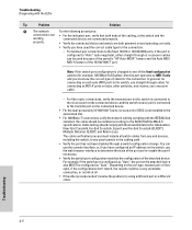
...-through a switch configuration change. You can be configured as "Auto", the port on the switch, use the console interface, or, if you have used because of the switch's "HP Auto-MDIX" feature and the Auto MDI/ MDI-X feature of the 10/100/1000-T port. Troubleshooting Diagnosing with the LEDs Tip Problem Solution ➏ The network Try the following procedures: connection is not • For the indicated port, verify that both powered on and...
...-through a switch configuration change. You can be configured as "Auto", the port on the switch, use the console interface, or, if you have used because of the switch's "HP Auto-MDIX" feature and the Auto MDI/ MDI-X feature of the 10/100/1000-T port. Troubleshooting Diagnosing with the LEDs Tip Problem Solution ➏ The network Try the following procedures: connection is not • For the indicated port, verify that both powered on and...
User Manual
Page 77
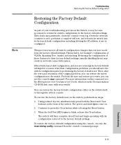
... to return the switch configuration to the factory default settings. The power and fault lights come on the front of VLANs, Spanning Tree, trunks, and stacking. To restore the factory default configuration using the console, execute the erase startup-config command from the factory default settings. This clears any passwords, clears the console event log, resets the network counters to zero, performs a complete self test, and reboots the switch into its configuration restored to the factory default settings. This process removes all switch configuration changes that came with...
... to return the switch configuration to the factory default settings. The power and fault lights come on the front of VLANs, Spanning Tree, trunks, and stacking. To restore the factory default configuration using the console, execute the erase startup-config command from the factory default settings. This clears any passwords, clears the console event log, resets the network counters to zero, performs a complete self test, and reboots the switch into its configuration restored to the factory default settings. This process removes all switch configuration changes that came with...

User Manual
Page 78
... your switch for information on the Documentation CDROM that came with your network records network addresses assigned to use of a number of automated electronic services. For more information, see the Management and Configuration Guide, which is on how to the relevant devices Troubleshooting 4-12 Troubleshooting Downloading New Switch Software Downloading New Switch Software When product enhancements occur for the Series 2600 Switches, new software can provide you are still having trouble with services offered by HP.
... your switch for information on the Documentation CDROM that came with your network records network addresses assigned to use of a number of automated electronic services. For more information, see the Management and Configuration Guide, which is on how to the relevant devices Troubleshooting 4-12 Troubleshooting Downloading New Switch Software Downloading New Switch Software When product enhancements occur for the Series 2600 Switches, new software can provide you are still having trouble with services offered by HP.

User Manual
Page 109
...used with ... 2-6 1000Base-SX connections, length limitations ... 2-6 ports, cables used with ... 2-6 1000Base-T connections, length limitations ... 2-5 ports, cables used with ... 2-35, 2-38-2-39 basic switch configuration IP address ... 3-3 manager password ... 3-2 subnet mask ... 3-3 Switch Setup screen ... 3-2 basic troubleshooting tips ... 4-1 blinking LEDs error indications ... 4-4 Bootp automatic switch configuration ... 3-2 for direct console connection ... 2-31 Index - 1 Index A-2 auto MDI/MDI-X operation ... B-2 1000Base-LX connections ... 2-6 fiber-optic cable specifications...
...used with ... 2-6 1000Base-SX connections, length limitations ... 2-6 ports, cables used with ... 2-6 1000Base-T connections, length limitations ... 2-5 ports, cables used with ... 2-35, 2-38-2-39 basic switch configuration IP address ... 3-3 manager password ... 3-2 subnet mask ... 3-3 Switch Setup screen ... 3-2 basic troubleshooting tips ... 4-1 blinking LEDs error indications ... 4-4 Bootp automatic switch configuration ... 3-2 for direct console connection ... 2-31 Index - 1 Index A-2 auto MDI/MDI-X operation ... B-2 1000Base-LX connections ... 2-6 fiber-optic cable specifications...

User Manual
Page 111
... MDI-X to a power source ... 2-19 horizontal surface mounting ... 2-19 location considerations ... 2-6 network cable requirements ... 2-5 precautions ... 2-4 rack or cabinet mounting ... 2-11 site preparation ... 2-5 wall mounting ... 2-16 IP address configuring ... 3-3 IP telephones ... 2-36 L laser specifications ... B-2 1000Base-LH ... B-5 I in-band ... 3-1 in-band console access types of mini-GBICs ... 2-7 G Gigabit-LH ports, cables used with ... B-2 Gigabit-SX ports, cables used with ... Fault LED ... 1-4 behavior during self test ... 2-11 behaviors ... 1-4 blinking definition...
... MDI-X to a power source ... 2-19 horizontal surface mounting ... 2-19 location considerations ... 2-6 network cable requirements ... 2-5 precautions ... 2-4 rack or cabinet mounting ... 2-11 site preparation ... 2-5 wall mounting ... 2-16 IP address configuring ... 3-3 IP telephones ... 2-36 L laser specifications ... B-2 1000Base-LH ... B-5 I in-band ... 3-1 in-band console access types of mini-GBICs ... 2-7 G Gigabit-LH ports, cables used with ... B-2 Gigabit-SX ports, cables used with ... Fault LED ... 1-4 behavior during self test ... 2-11 behaviors ... 1-4 blinking definition...

User Manual
Page 113
... test ... 2-10 serial cable for direct console connection ... 2-31 SFP ports ... 1-2 slots for troubleshooting ... 4-1 topologies effects of improper topology ... 4-2 samples of ... 2-32, 2-36 Index Index - 5 A-3 straight-through cable pin-out ... resetting the switch factory default reset ... 4-11 location of cables used with the switch ... 2-5 switch connecting to a power source ... 2-19 description ... 1-1 downloading new software ... 4-12 electrical specifications ... A-1 environmental ... A-2 features ... 1-11 front panel description ... 1-3 included parts ... 2-1 LED descriptions...
... test ... 2-10 serial cable for direct console connection ... 2-31 SFP ports ... 1-2 slots for troubleshooting ... 4-1 topologies effects of improper topology ... 4-2 samples of ... 2-32, 2-36 Index Index - 5 A-3 straight-through cable pin-out ... resetting the switch factory default reset ... 4-11 location of cables used with the switch ... 2-5 switch connecting to a power source ... 2-19 description ... 1-1 downloading new software ... 4-12 electrical specifications ... A-1 environmental ... A-2 features ... 1-11 front panel description ... 1-3 included parts ... 2-1 LED descriptions...


