
Data Sheet
Page 1
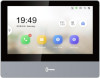
DS-KH8350-WTE1 Indoor Station 7-inch IPS touch screen with 1024 × 600 resolution Reddot award winner Convenient Hik-Connect APP Mobile Control Receive calls, open the door and live view remotely Easy to use without PC Easy wizard for quick set up Configure the whole system on one touch screen Rich functions and extensions Live...
DS-KH8350-WTE1 Indoor Station 7-inch IPS touch screen with 1024 × 600 resolution Reddot award winner Convenient Hik-Connect APP Mobile Control Receive calls, open the door and live view remotely Easy to use without PC Easy wizard for quick set up Configure the whole system on one touch screen Rich functions and extensions Live...
Data Sheet
Page 3
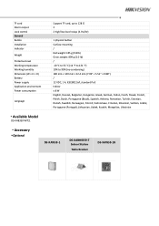
TF card Alarm output Lock control General Button Installation Indicator Weight Protective level Working temperature Working humidity Dimension (W × H × D) Battery Power supply Application environment Power consumption Language Support TF card, up to 128 G 2 2 high/low level relays (3.3V/0V) 1 physical button Surface mounting / Net weight: 355 g (0.8 lb) Gross weight: 899 g (2.0 ... (Portugal), Lithuanian, Uzbek, Kazakh, Mongolian, Ukrainian Available Model DS-KH8350-WTE1 Accessory Optional DS-KAW50-1 DS-KABH8350-T Indoor Station Table Bracket DS-KAW50-1N
TF card Alarm output Lock control General Button Installation Indicator Weight Protective level Working temperature Working humidity Dimension (W × H × D) Battery Power supply Application environment Power consumption Language Support TF card, up to 128 G 2 2 high/low level relays (3.3V/0V) 1 physical button Surface mounting / Net weight: 355 g (0.8 lb) Gross weight: 899 g (2.0 ... (Portugal), Lithuanian, Uzbek, Kazakh, Mongolian, Ukrainian Available Model DS-KH8350-WTE1 Accessory Optional DS-KAW50-1 DS-KABH8350-T Indoor Station Table Bracket DS-KAW50-1N
Quick Start Guide
Page 1
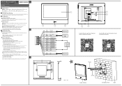
... on Guide (Scan the QR code) for detailed informa on. 2 Terminal and Wiring There are 20 pins in good condi on UD20185B ENGLISH Diagram References 1 Appearance 1 Screen 2 Microphone 3 Unlock Key 4 Loudspeaker 5 SD Card Slot 6 Debugging Port 7 Network Interface 8 Power/Alarm Terminal Note: The appearance of the door sta on . e. a. Tap Finish to save the se ngs. 5. Refers to pop up the Network Se ngs page. Linked...
... on Guide (Scan the QR code) for detailed informa on. 2 Terminal and Wiring There are 20 pins in good condi on UD20185B ENGLISH Diagram References 1 Appearance 1 Screen 2 Microphone 3 Unlock Key 4 Loudspeaker 5 SD Card Slot 6 Debugging Port 7 Network Interface 8 Power/Alarm Terminal Note: The appearance of the door sta on . e. a. Tap Finish to save the se ngs. 5. Refers to pop up the Network Se ngs page. Linked...
Operation Manual
Page 5
... product does not work properly, please contact your local region. ● Please use . Transportation without the original wrapper may result in damage on the device and lead to the factory with the original wrapper. The power consumption cannot be less than the required value. ● Do not connect several devices to direct sun light, low ventilation or...
... product does not work properly, please contact your local region. ● Please use . Transportation without the original wrapper may result in damage on the device and lead to the factory with the original wrapper. The power consumption cannot be less than the required value. ● Do not connect several devices to direct sun light, low ventilation or...
Operation Manual
Page 6
Network Indoor Station Operation Guide ● Improper use or replacement of the battery may result in hazard of used batteries according to the instructions provided by the battery manufacturer. ● Input voltage should meet both the SELV and the Limited Power Source according to 60950-1 standard. ● The power supply must conform to LPS. Replace with the same or equivalent type only. The recommended adaptor models and manufacturers...
Network Indoor Station Operation Guide ● Improper use or replacement of the battery may result in hazard of used batteries according to the instructions provided by the battery manufacturer. ● Input voltage should meet both the SELV and the Limited Power Source according to 60950-1 standard. ● The power supply must conform to LPS. Replace with the same or equivalent type only. The recommended adaptor models and manufacturers...
Operation Manual
Page 7
... the dealer or an experienced radio/TV technician for help This equipment should be determined by turning the equipment off and on a circuit different from that to which the receiver is subject to provide reasonable protection against harmful interference in a particular installation. Network Indoor Station Operation Guide Regulatory Information FCC Information Please take attention that changes or modification not expressly approved by...
... the dealer or an experienced radio/TV technician for help This equipment should be determined by turning the equipment off and on a circuit different from that to which the receiver is subject to provide reasonable protection against harmful interference in a particular installation. Network Indoor Station Operation Guide Regulatory Information FCC Information Please take attention that changes or modification not expressly approved by...
Operation Manual
Page 8
... power (e.i.r.p.) is not more information see : www.recyclethis.info 2006/66/EC (battery directive): This product contains a battery that may only operate using an antenna of a type and maximum (or lesser) gain approved for the transmitter by Industry Canada. L'exploitation est autorisée aux deux conditions suivantes : 1. Under Industry Canada regulations, this radio transmitter may cause undesired operation of the device. Network Indoor Station Operation Guide...
... power (e.i.r.p.) is not more information see : www.recyclethis.info 2006/66/EC (battery directive): This product contains a battery that may only operate using an antenna of a type and maximum (or lesser) gain approved for the transmitter by Industry Canada. L'exploitation est autorisée aux deux conditions suivantes : 1. Under Industry Canada regulations, this radio transmitter may cause undesired operation of the device. Network Indoor Station Operation Guide...

Operation Manual
Page 10
Network Indoor Station Operation Guide Contents Chapter 1 About this Manual ...1 Chapter 2 Local Operation ...2 2.1 Call Settings ...2 2.1.1 Add Contact ...2 2.1.2 Call Resident ...3 2.1.3 Call Indoor Extension/Indoor Station 4 2.1.4 Receive Call ...4 2.1.5 View Call Logs ...4 2.2 Leave Message ...5 2.3 Live View ...6 2.4 Arming Mode Settings ...7 2.5 Arm/Disarm ...8 2.5.1 Arm Room ...8 2.5.2 Disarm Room ...9 2.6 Call Elevator ...9 2.7 Relay Settings ...10 2.8 Information Management ...10 Chapter 3 Remote Operation via the client software 12 3.1 Call Indoor Station ...12 3.2 Receive Call ...
Network Indoor Station Operation Guide Contents Chapter 1 About this Manual ...1 Chapter 2 Local Operation ...2 2.1 Call Settings ...2 2.1.1 Add Contact ...2 2.1.2 Call Resident ...3 2.1.3 Call Indoor Extension/Indoor Station 4 2.1.4 Receive Call ...4 2.1.5 View Call Logs ...4 2.2 Leave Message ...5 2.3 Live View ...6 2.4 Arming Mode Settings ...7 2.5 Arm/Disarm ...8 2.5.1 Arm Room ...8 2.5.2 Disarm Room ...9 2.6 Call Elevator ...9 2.7 Relay Settings ...10 2.8 Information Management ...10 Chapter 3 Remote Operation via the client software 12 3.1 Call Indoor Station ...12 3.2 Receive Call ...

Operation Manual
Page 21
... Station Operation Guide Figure 2-8 Call Elevator 2. Back to start /stop working. 2.8 Information Management You can control the relay manually. Tap Settings → → Output Settings and disable Hide on the home page to start calling the elevator. 3. Steps 1. Tap Message on Main Page function. 2. Select a relay to enable or disable, the control device will start calling the elevator. 2.7 Relay Settings After you set the output parameters and display...
... Station Operation Guide Figure 2-8 Call Elevator 2. Back to start /stop working. 2.8 Information Management You can control the relay manually. Tap Settings → → Output Settings and disable Hide on the home page to start calling the elevator. 3. Steps 1. Tap Message on Main Page function. 2. Select a relay to enable or disable, the control device will start calling the elevator. 2.7 Relay Settings After you set the output parameters and display...
Operation Manual
Page 24
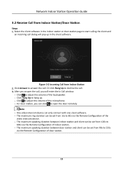
Network Indoor Station Operation Guide 3.2 Receive Call from Indoor Station 2. Figure 3-2 Incoming Call from Indoor Station/Door Station Steps 1. Or click Hang Up to answer the call . 3. Click Answer to decline the call . Select the client software in the client software. After you answer the call dialog will enter the In Call window. ● Click to adjust the volume of the loudspeaker. ● Click...
Network Indoor Station Operation Guide 3.2 Receive Call from Indoor Station 2. Figure 3-2 Incoming Call from Indoor Station/Door Station Steps 1. Or click Hang Up to answer the call . 3. Click Answer to decline the call . Select the client software in the client software. After you answer the call dialog will enter the In Call window. ● Click to adjust the volume of the loudspeaker. ● Click...
Operation Manual
Page 33
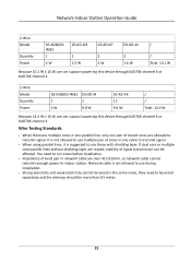
Network Indoor Station Operation Guide 2-Wire Model Quantity Power DS-KD8003IME2 1 4 W DS-KD-DIS 1 2.5 W DS-KD-KP 2 2 W DS-KD-M 2 1.6 W / / Total: 10.1 W Because 10.1 W ≤ 16 W, we can support powering this device through KAD706 channel 6 or KAD704 channel 4. 2-Wire Model Quantity Power DS-KD8003-IME2 1 4 W DS-KD-M 1 0.8 W DS-KD-KK 12 9.6 W / / Total: 14.4 W Because 14.4 W ≤ 16 W, we can be more than 0.5 meter. 22 Wire Testing Standards ● When there are allowed to transmit signal. Network cable is...
Network Indoor Station Operation Guide 2-Wire Model Quantity Power DS-KD8003IME2 1 4 W DS-KD-DIS 1 2.5 W DS-KD-KP 2 2 W DS-KD-M 2 1.6 W / / Total: 10.1 W Because 10.1 W ≤ 16 W, we can support powering this device through KAD706 channel 6 or KAD704 channel 4. 2-Wire Model Quantity Power DS-KD8003-IME2 1 4 W DS-KD-M 1 0.8 W DS-KD-KK 12 9.6 W / / Total: 14.4 W Because 14.4 W ≤ 16 W, we can be more than 0.5 meter. 22 Wire Testing Standards ● When there are allowed to transmit signal. Network cable is...

Configuration Guide
Page 6
... radio peut fonctionner avec une antenne d'un type et d'un gain maximal (ou inférieur) approuvé pour l'émetteur par Industrie Canada. Operation is marked with this symbol, which may only operate using an antenna of a type and maximum (or lesser) gain approved for specific battery information. Network Indoor Station Configuration Guide under the EMC Directive 2014/30/EU, RE Directive...
... radio peut fonctionner avec une antenne d'un type et d'un gain maximal (ou inférieur) approuvé pour l'émetteur par Industrie Canada. Operation is marked with this symbol, which may only operate using an antenna of a type and maximum (or lesser) gain approved for specific battery information. Network Indoor Station Configuration Guide under the EMC Directive 2014/30/EU, RE Directive...
Configuration Guide
Page 8
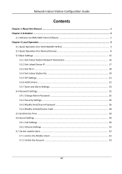
Network Indoor Station Configuration Guide Contents Chapter 1 About this Manual ...1 Chapter 2 Activation ...2 2.1 Activate via iVMS-4200 Client Software 2 Chapter 3 Local Operation ...3 3.1 Quick Operation (For DS-KH6320EY-WTE2 3 3.2 Quick Operation (For Normal Device 8 3.3 Basic Settings ...15 3.3.1 Set Indoor Station Network Parameters 16 3.3.2 Set Linked Device IP ...17 3.3.3 Set Wi-Fi ...18 3.3.4 Set Indoor Station No 19 3.3.5 SIP Settings ...21 3.3.6 Add Camera ...22 3.3.7 Zone and Alarm Settings 23 3.4 Password Settings ...25 3.4.1 Change Admin Password 25 3.4.2 Security Settings...
Network Indoor Station Configuration Guide Contents Chapter 1 About this Manual ...1 Chapter 2 Activation ...2 2.1 Activate via iVMS-4200 Client Software 2 Chapter 3 Local Operation ...3 3.1 Quick Operation (For DS-KH6320EY-WTE2 3 3.2 Quick Operation (For Normal Device 8 3.3 Basic Settings ...15 3.3.1 Set Indoor Station Network Parameters 16 3.3.2 Set Linked Device IP ...17 3.3.3 Set Wi-Fi ...18 3.3.4 Set Indoor Station No 19 3.3.5 SIP Settings ...21 3.3.6 Add Camera ...22 3.3.7 Zone and Alarm Settings 23 3.4 Password Settings ...25 3.4.1 Change Admin Password 25 3.4.2 Security Settings...
Configuration Guide
Page 9
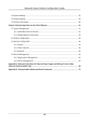
... and Device Command 72 viii Relevant Instructions for External Power Supply and Wiring of 2-wire Video Intercom Products (2020-1-20 69 Appendix B. Network Indoor Station Configuration Guide 3.8 System Settings ...35 3.9 Output Settings ...39 3.10 Device Information ...40 Chapter 4 Remote Operation via the Client Software 41 4.1 Device Management ...41 4.1.1 Add Video Intercom Devices 41 4.1.2 Modify Network Information 43 4.2 System Configuration ...44 4.3 Remote Configuration ...44 4.3.1 System ...44 4.3.2 Video Intercom ...50 4.3.3 Network ...60 4.4 Person Management ...64...
... and Device Command 72 viii Relevant Instructions for External Power Supply and Wiring of 2-wire Video Intercom Products (2020-1-20 69 Appendix B. Network Indoor Station Configuration Guide 3.8 System Settings ...35 3.9 Output Settings ...39 3.10 Device Information ...40 Chapter 4 Remote Operation via the Client Software 41 4.1 Device Management ...41 4.1.1 Add Video Intercom Devices 41 4.1.2 Modify Network Information 43 4.2 System Configuration ...44 4.3 Remote Configuration ...44 4.3.1 System ...44 4.3.2 Video Intercom ...50 4.3.3 Network ...60 4.4 Person Management ...64...

Configuration Guide
Page 16
.... 1) Enable Hik-Connect service. 2) Edit verification code or use the activation password by default. 3) View Hik-Connect Server Status. 4) Scan the first QR Code to connect. The indoor extension with the same LAN as the indoor station will be displayed in the list. 6. Set time and tap Next. 1) Select the Time Zone. 2) Tap Date Format and Time Format to set time manually. 4) Enable DST.Set the DST start time, end time and bias time. 7 Network Indoor Station Configuration Guide 4.
.... 1) Enable Hik-Connect service. 2) Edit verification code or use the activation password by default. 3) View Hik-Connect Server Status. 4) Scan the first QR Code to connect. The indoor extension with the same LAN as the indoor station will be displayed in the list. 6. Set time and tap Next. 1) Select the Time Zone. 2) Tap Date Format and Time Format to set time manually. 4) Enable DST.Set the DST start time, end time and bias time. 7 Network Indoor Station Configuration Guide 4.
Configuration Guide
Page 19
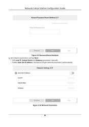
Enable Auto Get IP address, the device will get network parameters automatically. Figure 3-10 Network Parameters 10 Edit Local IP, Subnet Mask and Gateway parameters manually. - Set network parameters and tap Next. - Network Indoor Station Configuration Guide Figure 3-9 Password Reset Methods 3.
Enable Auto Get IP address, the device will get network parameters automatically. Figure 3-10 Network Parameters 10 Edit Local IP, Subnet Mask and Gateway parameters manually. - Set network parameters and tap Next. - Network Indoor Station Configuration Guide Figure 3-9 Password Reset Methods 3.

Configuration Guide
Page 21
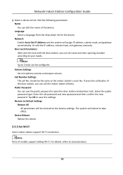
Set time and tap Next. 1) Select the Time Zone. 2) Tap Date Format and Time Format to set the time format. 3) Tap Time to set time manually. 4) Enable DST.Set the DST start time, end time and bias time. 12 Network Indoor Station Configuration Guide Figure 3-12 Wi-Fi 6.
Set time and tap Next. 1) Select the Time Zone. 2) Tap Date Format and Time Format to set the time format. 3) Tap Time to set time manually. 4) Enable DST.Set the DST start time, end time and bias time. 12 Network Indoor Station Configuration Guide Figure 3-12 Wi-Fi 6.
Configuration Guide
Page 27
.... Call Number Settings The call the indoor station directly. Door Lock Parameters After wire the lock with the door station, you can use the public password to your needs. Network Indoor Station Configuration Guide 3. Public Password You can call No. Tap OK to link. Network Enable Auto Get IP Address and the system will reboot to take effect. Restore to the factory settings. Select a device to save the settings. Volume Settings Set microphone volume and output volume. should...
.... Call Number Settings The call the indoor station directly. Door Lock Parameters After wire the lock with the door station, you can use the public password to your needs. Network Indoor Station Configuration Guide 3. Public Password You can call No. Tap OK to link. Network Enable Auto Get IP Address and the system will reboot to take effect. Restore to the factory settings. Select a device to save the settings. Volume Settings Set microphone volume and output volume. should...

Configuration Guide
Page 29
to : SIP Settings Password Settings You can set unlock password and duress code. 3. SIP Settings You can be omitted if there is no such information. ● If there are two indoor stations that are in building 1. can set the duration of live view. directly to set the room information, live view duration, SIP parameters and password. Live View Duration You can set the room information, live view duration, registration password and enable...
to : SIP Settings Password Settings You can set unlock password and duress code. 3. SIP Settings You can be omitted if there is no such information. ● If there are two indoor stations that are in building 1. can set the duration of live view. directly to set the room information, live view duration, SIP parameters and password. Live View Duration You can set the room information, live view duration, registration password and enable...

Configuration Guide
Page 48
... page or not. Steps 1. Select a relay and set and control the connected output devices via the output settings page. Network Indoor Station Configuration Guide Wizard Tap Wizard and set to display the relay button on the Preference page. You can change the relay' name, and open duration. Note ● Supports up to enter the preference page. Refers to Quick Operation (For Normal Device) for the details.
... page or not. Steps 1. Select a relay and set and control the connected output devices via the output settings page. Network Indoor Station Configuration Guide Wizard Tap Wizard and set to display the relay button on the Preference page. You can change the relay' name, and open duration. Note ● Supports up to enter the preference page. Refers to Quick Operation (For Normal Device) for the details.
