
Specifications
Page 5
... 26 Table 14. Drive ready time 21 Table 12. Interface connector pin assignments 39 Figure 4. Mechanical positioning performance 19 Table 6. Operating mode 21 Table 11. Cylinder allocation 17 Table 4. Full stroke seek time 19 Table 7. 5K320 SATA OEM Specification 14.28 Security Erase Prepare (F3h 128 14.29 Security Erase Unit (F4h 129 14.30 Security Freeze Lock (F5h 131 14.31 Security Set Password (F1h 132 14.32 Security Unlock (F2h)...134 14...
... 26 Table 14. Drive ready time 21 Table 12. Interface connector pin assignments 39 Figure 4. Mechanical positioning performance 19 Table 6. Operating mode 21 Table 11. Cylinder allocation 17 Table 4. Full stroke seek time 19 Table 7. 5K320 SATA OEM Specification 14.28 Security Erase Prepare (F3h 128 14.29 Security Erase Unit (F4h 129 14.30 Security Freeze Lock (F5h 131 14.31 Security Set Password (F1h 132 14.32 Security Unlock (F2h)...134 14...

Specifications
Page 6
... Extended comprehensive SMART error Log 112 6 continued 64 Table 37 Set Max Set Password data content 66 Table 38 Preserved Software Setting 70 Table 39 SCT Action Code Supported 71 Table 40 Command set 75 Table 41 Command Set - Continued --- 99 Table 63 Identify device information --- Nonoperating shock 35 Table 22. Continued --- 93 Table 57 Identify device information --- Continued --- 96 Table 60 Identify device information --- 5K320 SATA OEM Specification Table 15. Power consumption efficiency 28...
... Extended comprehensive SMART error Log 112 6 continued 64 Table 37 Set Max Set Password data content 66 Table 38 Preserved Software Setting 70 Table 39 SCT Action Code Supported 71 Table 40 Command set 75 Table 41 Command Set - Continued --- 99 Table 63 Identify device information --- Nonoperating shock 35 Table 22. Continued --- 93 Table 57 Identify device information --- Continued --- 96 Table 60 Identify device information --- 5K320 SATA OEM Specification Table 15. Power consumption efficiency 28...

Specifications
Page 39
In this case, the mating sequences are three power pins for pre-charge in the backplane blind-mate situation. If a device uses 3.3V, then all V33 pins must be terminated. One pin from the host system to the hard disk drive plus circuit pattern length in the host system shall not exceed 1 meter. 7.2 Interface connector The figure below shows the physical pin location...
In this case, the mating sequences are three power pins for pre-charge in the backplane blind-mate situation. If a device uses 3.3V, then all V33 pins must be terminated. One pin from the host system to the hard disk drive plus circuit pattern length in the host system shall not exceed 1 meter. 7.2 Interface connector The figure below shows the physical pin location...

Specifications
Page 51
... tests speed and other case, the device does not change current mode. (*5) According to the initial power mode selection. (*6) See 12.15 Software Setting Preservation Feature Set. o o Aborting Device operation - (*1) (*1) Initialization of hardware O x x Internal diagnostic O x x Starting spindle motor (*5) x x Initialization of sleep mode, the device goes to default O (*6) (*3) - Multiple mode - The device resets the interface circuitry as well as shown in Serial ATA bus. execute X ---- not execute Note. (*1) Execute after the data in write cache...
... tests speed and other case, the device does not change current mode. (*5) According to the initial power mode selection. (*6) See 12.15 Software Setting Preservation Feature Set. o o Aborting Device operation - (*1) (*1) Initialization of hardware O x x Internal diagnostic O x x Starting spindle motor (*5) x x Initialization of sleep mode, the device goes to default O (*6) (*3) - Multiple mode - The device resets the interface circuitry as well as shown in Serial ATA bus. execute X ---- not execute Note. (*1) Execute after the data in write cache...

Specifications
Page 52
... Reset considerations The Set Max password, the Set Max security mode and the Set Max unlock counter don't retain over a Power On Reset but persist over a COMRESET or Soft Reset. 5K320 SATA OEM Specification Register Error Sector Count LBA Low LBA Mid LBA High Device Status Alternate Status Table 30 Default Register Values Default Value Diagnostic Code 01h 01h 00h 00h 00h 50h 50h The meaning of the Error Register diagnostic codes resulting from power on, COMRESET or the Execute Device Diagnostic command...
... Reset considerations The Set Max password, the Set Max security mode and the Set Max unlock counter don't retain over a Power On Reset but persist over a COMRESET or Soft Reset. 5K320 SATA OEM Specification Register Error Sector Count LBA Low LBA Mid LBA High Device Status Alternate Status Table 30 Default Register Values Default Value Diagnostic Code 01h 01h 00h 00h 00h 50h 50h The meaning of the Error Register diagnostic codes resulting from power on, COMRESET or the Execute Device Diagnostic command...

Specifications
Page 54
... selects a CHS translation mode using the L bit in the DEVICE register. The device then computes the number of logical cylinders available in effect, the LBA address of a given logical sector does not change. The current CHS translation mode also is made up of three fields: the cylinder number, the head number and the sector number. Cylinders are the current translation mode values. Device 12.4 Sector Addressing Mode 5K320 SATA OEM Specification All addressing of data sectors...
... selects a CHS translation mode using the L bit in the DEVICE register. The device then computes the number of logical cylinders available in effect, the LBA address of a given logical sector does not change. The current CHS translation mode also is made up of three fields: the cylinder number, the head number and the sector number. Cylinders are the current translation mode values. Device 12.4 Sector Addressing Mode 5K320 SATA OEM Specification All addressing of data sectors...

Specifications
Page 58
.... Each attribute threshold represents the lowest limit to hard disk device even if the device is not enabled. If the attribute auto save feature is removed from 1 through design and reliability testing and analysis. There is enabled, attribute values will be changed in the field. Device Locked mode Device Unlocked mode The device disables media access commands after power on every head unload timing except the emergency unload, even if the attribute...
.... Each attribute threshold represents the lowest limit to hard disk device even if the device is not enabled. If the attribute auto save feature is removed from 1 through design and reliability testing and analysis. There is enabled, attribute values will be changed in the field. Device Locked mode Device Unlocked mode The device disables media access commands after power on every head unload timing except the emergency unload, even if the attribute...

Specifications
Page 59
... Specification entered after power on, otherwise it is entered by a system user. Device Frozen mode The device enables all commands except those which is locked with the master password. Value 0000h and FFFFh is reserved. 12.9.5 Operation example 12.9.5.1 Master Password setting The system manufacturer/dealer can be unlocked via a Security Freeze Lock command. Then user data is FFFEh. User Password The User Password should be given or changed by a security unlock or a security erase unit command. If Software Setting Preservation is disabled, the device...
... Specification entered after power on, otherwise it is entered by a system user. Device Frozen mode The device enables all commands except those which is locked with the master password. Value 0000h and FFFFh is reserved. 12.9.5 Operation example 12.9.5.1 Master Password setting The system manufacturer/dealer can be unlocked via a Security Freeze Lock command. Then user data is FFFEh. User Password The User Password should be given or changed by a security unlock or a security erase unit command. If Software Setting Preservation is disabled, the device...

Specifications
Page 70
... cylinder Capacity Time to fall into standby mode Security freeze lock Security unlock Capacity Write Cache Enable/Disable Set Transfer Mode Advanced Power Management Enable/Disable Read Look-Ahead Reverting to issue a command in ATA8-ACS specification for more detail. Log page E1h is supported. Please refer to issue commands and return status. Action code Description 0002h Write Same command - 70 - Log page E0h is used to Defaults Block size 12.16 Native Command Queuing Native Command Queuing feature (Read / Write FPDMA Queued commands) is used...
... cylinder Capacity Time to fall into standby mode Security freeze lock Security unlock Capacity Write Cache Enable/Disable Set Transfer Mode Advanced Power Management Enable/Disable Read Look-Ahead Reverting to issue a command in ATA8-ACS specification for more detail. Log page E1h is supported. Please refer to issue commands and return status. Action code Description 0002h Write Same command - 70 - Log page E0h is used to Defaults Block size 12.16 Native Command Queuing Native Command Queuing feature (Read / Write FPDMA Queued commands) is used...

Specifications
Page 73
...; Security Unlock Set Max Set Password Set Max Unlock S.M.A.R.T Write Log Sector Write Buffer Write Log Ext Write Multiple Write Multiple Ext Write Sector(s) Write Sector(s) Ext Execution includes the transfer of one or more 512 byte (>512 bytes on Write Long) sectors of Device register on issuing the command. 13.3 Non-Data Commands These commands are: Check Power Mode Device Configuration Freeze Lock Device Configuration Restore Execute Device Diagnostic Flush Cache...
...; Security Unlock Set Max Set Password Set Max Unlock S.M.A.R.T Write Log Sector Write Buffer Write Log Ext Write Multiple Write Multiple Ext Write Sector(s) Write Sector(s) Ext Execution includes the transfer of one or more 512 byte (>512 bytes on Write Long) sectors of Device register on issuing the command. 13.3 Non-Data Commands These commands are: Check Power Mode Device Configuration Freeze Lock Device Configuration Restore Execute Device Diagnostic Flush Cache...

Specifications
Page 75
... 3 Initialize Device Parameters 1 Read Buffer 4 Read DMA 4 Read DMA 4 Read DMA Ext 5 Read FPDMA Queued 1 Read Log Ext 1 Read Multiple 1 Read Multiple Ext 3 Read Native Max Address 3 Read Native Max Address Ext 1 Read Sector(s) 1 Read Sector(s) 1 Read Sector(s) Ext 3 Read Verify Sector(s) 3 Read Verify Sector(s) 3 Read Verify Sector(s) Ext 3 Recalibrate 2 Security Disable Password 3 Security Erase Prepare 2 Security Erase Unit 3 Security Freeze Lock 2 Security Set Password 2 Security Unlock 3 Seek 3 Sense Condition 3 Set Features Table 40 Command set 75 5K320 SATA OEM Specification Code (Hex...
... 3 Initialize Device Parameters 1 Read Buffer 4 Read DMA 4 Read DMA 4 Read DMA Ext 5 Read FPDMA Queued 1 Read Log Ext 1 Read Multiple 1 Read Multiple Ext 3 Read Native Max Address 3 Read Native Max Address Ext 1 Read Sector(s) 1 Read Sector(s) 1 Read Sector(s) Ext 3 Read Verify Sector(s) 3 Read Verify Sector(s) 3 Read Verify Sector(s) Ext 3 Recalibrate 2 Security Disable Password 3 Security Erase Prepare 2 Security Erase Unit 3 Security Freeze Lock 2 Security Set Password 2 Security Unlock 3 Seek 3 Sense Condition 3 Set Features Table 40 Command set 75 5K320 SATA OEM Specification Code (Hex...

Specifications
Page 77
.... Enable/Disable Attribute Autosave S.M.A.R.T. Zero specifies CHS mode and one does LBA addressing mode. (S.M.A.R.T Function) S.M.A.R.T. Read Attribute Values S.M.A.R.T. Read Attribute Thresholds S.M.A.R.T. Enable/Disable Automatic Off-line (Set Features) Enable Write Cache Set Transfer Mode Enable Advanced Power Management feature Enable Power-Up in Standby feature Power-Up in Standby feature device Spin-Up Enable use of Serial ATA feature Disable read look-ahead feature Disable reverting to power on Page 77 shows the sub-commands that the head number part of the Sector Count...
.... Enable/Disable Attribute Autosave S.M.A.R.T. Zero specifies CHS mode and one does LBA addressing mode. (S.M.A.R.T Function) S.M.A.R.T. Read Attribute Values S.M.A.R.T. Read Attribute Thresholds S.M.A.R.T. Enable/Disable Automatic Off-line (Set Features) Enable Write Cache Set Transfer Mode Enable Advanced Power Management feature Enable Power-Up in Standby feature Power-Up in Standby feature device Spin-Up Enable use of Serial ATA feature Disable read look-ahead feature Disable reverting to power on Page 77 shows the sub-commands that the head number part of the Sector Count...

Specifications
Page 82
... supported 1 1 = SMART self-test supported 0 1 = SMART feature set supported 8 SATA feature 15-5 Reserved 4 1 = Software setting preservation supported 3 Reserved 2 1 = Interface power management supported 1 1 = Non-zero buffer offset in DMA Setup FIS supported 0 1 = Native command queuing supported 9-254 Reserved 255 Integrity word 15-8 Checksum 7-0 Signature (A5h) Table 46 Device Configuration Overlay Data structure Note. Bits 7:0 of this word contain the value A5h. Bits 15:8 of this word contain the data structure checksum. 5K320 SATA OEM Specification...
... supported 1 1 = SMART self-test supported 0 1 = SMART feature set supported 8 SATA feature 15-5 Reserved 4 1 = Software setting preservation supported 3 Reserved 2 1 = Interface power management supported 1 1 = Non-zero buffer offset in DMA Setup FIS supported 0 1 = Native command queuing supported 9-254 Reserved 255 Integrity word 15-8 Checksum 7-0 Signature (A5h) Table 46 Device Configuration Overlay Data structure Note. Bits 7:0 of this word contain the value A5h. Bits 15:8 of this word contain the data structure checksum. 5K320 SATA OEM Specification...
Specifications
Page 93
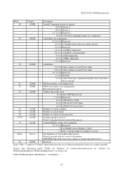
... Valid 54 xxxxH Number of current cylinders 55 xxxxH Number of current heads 56 xxxxH Number of current sectors per track 57-58 xxxxH Current capacity in 'Content' field indicates the use of those parameters that are valid 13- 2 (=0) Reserved 1 (=0) Obsolete 0 (=0) 1=the device has a minimum Standby timer value that is device specific 51 0200H * PIO data transfer cycle timing mode 52 0200H * DMA data transfer cycle timing mode Refer Word...
... Valid 54 xxxxH Number of current cylinders 55 xxxxH Number of current heads 56 xxxxH Number of current sectors per track 57-58 xxxxH Current capacity in 'Content' field indicates the use of those parameters that are valid 13- 2 (=0) Reserved 1 (=0) Obsolete 0 (=0) 1=the device has a minimum Standby timer value that is device specific 51 0200H * PIO data transfer cycle timing mode 52 0200H * DMA data transfer cycle timing mode Refer Word...

Specifications
Page 95
... Setup FIS enabled 0(=0) Reserved 80 01FCH Major version number ATA-2.3 and ATA/ATAPI-4, 5, 6, 7, 8 81 0042H Minor version number-ATA8-ACS revision 3f -- 82 746BH Command set supported 15 (=0) Reserved 14 (=1) 1=NOP command supported 13 (=1) 1=READ BUFFER command supported 12 (=1) 1=WRITE BUFFER command supported 11 (=0) Reserved 10 (=1) 1=Host Protected Area Feature Set supported 9 (=0) 1=DEVICE RESET command supported 8 (=0) 1=SERVICE interrupt supported 7 (=0) 1=release interrupt supported 6 (=1) 1=look-ahead supported 5 (=1) 1=write cache supported 4 (=0) 1=supports...
... Setup FIS enabled 0(=0) Reserved 80 01FCH Major version number ATA-2.3 and ATA/ATAPI-4, 5, 6, 7, 8 81 0042H Minor version number-ATA8-ACS revision 3f -- 82 746BH Command set supported 15 (=0) Reserved 14 (=1) 1=NOP command supported 13 (=1) 1=READ BUFFER command supported 12 (=1) 1=WRITE BUFFER command supported 11 (=0) Reserved 10 (=1) 1=Host Protected Area Feature Set supported 9 (=0) 1=DEVICE RESET command supported 8 (=0) 1=SERVICE interrupt supported 7 (=0) 1=release interrupt supported 6 (=1) 1=look-ahead supported 5 (=1) 1=write cache supported 4 (=0) 1=supports...

Specifications
Page 96
...CACHE EXT command supported 12 (=1) 1=FLUSH CACHE command supported 11 (=1) 1=Device Configuration Overlay command supported 10 (=1) 1=48-bit Address feature set supported 9 (=0) Reserved 8 (=1) 1=SET MAX security extension supported 7 (=0) Reserved 6 (=1) 1=SET FEATURES subcommand required to spin-up 5 (=1) 1=Power-Up In Standby feature set supported 4 (=0) 1=Removable Media Status Notification Feature Set supported 3 (=1) 1=Advanced Power Management Feature Set supported 2 (=0) 1=CFA Feature Set supported 1 (=0) 1=READ/WRITE DMA QUEUED supported 0 (=1) Download Microcode Command...
...CACHE EXT command supported 12 (=1) 1=FLUSH CACHE command supported 11 (=1) 1=Device Configuration Overlay command supported 10 (=1) 1=48-bit Address feature set supported 9 (=0) Reserved 8 (=1) 1=SET MAX security extension supported 7 (=0) Reserved 6 (=1) 1=SET FEATURES subcommand required to spin-up 5 (=1) 1=Power-Up In Standby feature set supported 4 (=0) 1=Removable Media Status Notification Feature Set supported 3 (=1) 1=Advanced Power Management Feature Set supported 2 (=0) 1=CFA Feature Set supported 1 (=0) 1=READ/WRITE DMA QUEUED supported 0 (=1) Download Microcode Command...

Specifications
Page 99
... 5 (=0) 1=Free-fall Control feature set is enabled 4 (=1) 1=Download Microcode with mode 3 is supported 3 (=0) 1=Read and Write DMA Ext GPL is supported 2 (=1) 1=WRITE UNCORRECTABLE is supported 1 (=0) 1=Write Read Verify feature set is enabled 0 (=0) Reserved 121-126 0000H Reserved 127 0000H Removable Media Status Notification feature set by Set Features Command (01h to FEh) 92 xxxxH Current Master Password Revision Codes 93 0000H Reserved 94 0000H Reserved 95 0000H Stream Minimum Request Size 96 0000H Streaming Transfer Time...
... 5 (=0) 1=Free-fall Control feature set is enabled 4 (=1) 1=Download Microcode with mode 3 is supported 3 (=0) 1=Read and Write DMA Ext GPL is supported 2 (=1) 1=WRITE UNCORRECTABLE is supported 1 (=0) 1=Write Read Verify feature set is enabled 0 (=0) Reserved 121-126 0000H Reserved 127 0000H Removable Media Status Notification feature set by Set Features Command (01h to FEh) 92 xxxxH Current Master Password Revision Codes 93 0000H Reserved 94 0000H Reserved 95 0000H Stream Minimum Request Size 96 0000H Streaming Transfer Time...

Specifications
Page 132
... the MASTER password is set by this command, the master password is registered internally, but the device is NOT locked after next COMRESET with Software Setting Preservation disabled or power on reset. Device -------- LBA Low -------- Status ...See Below... The security mode feature (device lock function) is enabled by this command, and the device is locked after next power on reset. One indicates that the device should check the given password against the user password stored internally. The device is not locked immediately. LBA Mid -------- Error...
... the MASTER password is set by this command, the master password is registered internally, but the device is NOT locked after next COMRESET with Software Setting Preservation disabled or power on reset. Device -------- LBA Low -------- Status ...See Below... The security mode feature (device lock function) is enabled by this command, and the device is locked after next power on reset. One indicates that the device should check the given password against the user password stored internally. The device is not locked immediately. LBA Mid -------- Error...

Specifications
Page 138
... type of auto reassigned sectors reaches the device's reassignment capacity, the write cache function will remain disabled. The deepest Power Saving mode is 05h (=Enable Advanced Power Management), the Sector Count Register specifies the Advanced Power Management level. 5K320 SATA OEM Specification When Feature register is set to 10h or 90h, the value set to the Sector Count register specifies the specific Serial ATA feature to the Identify Device Information(129word) by Identify Device command...
... type of auto reassigned sectors reaches the device's reassignment capacity, the write cache function will remain disabled. The deepest Power Saving mode is 05h (=Enable Advanced Power Management), the Sector Count Register specifies the Advanced Power Management level. 5K320 SATA OEM Specification When Feature register is set to 10h or 90h, the value set to the Sector Count register specifies the specific Serial ATA feature to the Identify Device Information(129word) by Identify Device command...

Specifications
Page 139
... accesses beyond that . Sector Count -------- The device receives this LBA as a Set Max security extension command which is supported, the value placed in Identify device information) is interpreted as subcommands. HHHH Status ...See Below... The Read Native Max Address command should be the same as a default value. In LBA mode, the Head number of the device. However, if the device contains greater than 268,435,455 sectors, the capacity addressable with this command 01h SET MAX SET PASSWORD...
... accesses beyond that . Sector Count -------- The device receives this LBA as a Set Max security extension command which is supported, the value placed in Identify device information) is interpreted as subcommands. HHHH Status ...See Below... The Read Native Max Address command should be the same as a default value. In LBA mode, the Head number of the device. However, if the device contains greater than 268,435,455 sectors, the capacity addressable with this command 01h SET MAX SET PASSWORD...


