
Installation Instructions
Page 1
... auxiliary or backup heat. CT87A,B,J Round® Thermostat LOW VOLTAGE (15 TO 30 VAC), THERMOSTAT AND MOUNTING HARDWARE 1 Verify that you have the correct thermostat Using the compatibility chart below, verify that you are unsure which model is compatible with 2-wire cooling-only systems. ® U.S. No No * CT87A is right for your system, visit www.honeywell.com/ yourhome...
... auxiliary or backup heat. CT87A,B,J Round® Thermostat LOW VOLTAGE (15 TO 30 VAC), THERMOSTAT AND MOUNTING HARDWARE 1 Verify that you have the correct thermostat Using the compatibility chart below, verify that you are unsure which model is compatible with 2-wire cooling-only systems. ® U.S. No No * CT87A is right for your system, visit www.honeywell.com/ yourhome...

Installation Instructions
Page 2
... the cover of your type of MERCURY SWITCH IN A THERMOSTAT system when you can be used to unscrew the cover if it is the current (amp) MERCURY SWITCH rating of your new thermostat; OLD THERMOSTAT ANTICIPATOR SCALE Current setting: If you cannot find the heat LEVER anticipator setting on the old thermostat, you reach Step 8 of M20206 this...
... the cover of your type of MERCURY SWITCH IN A THERMOSTAT system when you can be used to unscrew the cover if it is the current (amp) MERCURY SWITCH rating of your new thermostat; OLD THERMOSTAT ANTICIPATOR SCALE Current setting: If you cannot find the heat LEVER anticipator setting on the old thermostat, you reach Step 8 of M20206 this...

Installation Instructions
Page 3
...Label the wires using the letter of an old control containing mercury in the trash. Fig. 2. WIRES THROUGH WALL OPENING If this thermostat is replacing a control that came with the CT87. COVER RING WALLPLATE NO. 4 X 1 INCH SHEET METAL SCREWS (2) 3 THERMOSTAT WIRING OPENING M20188 69-0274-6 Do not label the wires by...sealed tube. 4 Install the cover ring and wallplate or subbase If installing on the wall (wallplate shown). Labeling wires. Fig. 4. stat (Fig. 2). CT87A,B,J ROUND® THERMOSTAT 5. Installing wallplate/subbase on the wall Refer to keep them from the old...
...Label the wires using the letter of an old control containing mercury in the trash. Fig. 2. WIRES THROUGH WALL OPENING If this thermostat is replacing a control that came with the CT87. COVER RING WALLPLATE NO. 4 X 1 INCH SHEET METAL SCREWS (2) 3 THERMOSTAT WIRING OPENING M20188 69-0274-6 Do not label the wires by...sealed tube. 4 Install the cover ring and wallplate or subbase If installing on the wall (wallplate shown). Labeling wires. Fig. 4. stat (Fig. 2). CT87A,B,J ROUND® THERMOSTAT 5. Installing wallplate/subbase on the wall Refer to keep them from the old...

Installation Instructions
Page 4
...box (subbase shown). 1/2 IN. holes at the locations you work. Reposition the cover ring (if used) and wallplate/subbase over the cover ring. ROUND HEAD SCREW (2) A THERMOSTAT WIRING HOLE 1 THE TWO INNER HOLES ARE USED WITH WALLPLATE. 2 IF OUTLET BOX IS HORIZONTAL, MOUNT COVER RING IN POSITION SHOWN, BUT FASTEN .... Position the wallplate or subbase. • If using the cover ring: Position the cover ring against the wall so that the fan and heating/cooling switches are aligned and the two screw holes on the left and right sides of the wallplate/subbase align with the screw holes on...
...box (subbase shown). 1/2 IN. holes at the locations you work. Reposition the cover ring (if used) and wallplate/subbase over the cover ring. ROUND HEAD SCREW (2) A THERMOSTAT WIRING HOLE 1 THE TWO INNER HOLES ARE USED WITH WALLPLATE. 2 IF OUTLET BOX IS HORIZONTAL, MOUNT COVER RING IN POSITION SHOWN, BUT FASTEN .... Position the wallplate or subbase. • If using the cover ring: Position the cover ring against the wall so that the fan and heating/cooling switches are aligned and the two screw holes on the left and right sides of the wallplate/subbase align with the screw holes on...

Installation Instructions
Page 5
...the screw holes on the left side of the cover ring is level. 5 69-0274-6 CT87A,B,J ROUND® THERMOSTAT 1. To level the subbase, use the leveling posts directly below the Heat and Fan indicators. Leveling the wallplate. Tighten the mounting screws after making sure that the wiring holes...The wallplate/subbase must be level to maintain accu- Loosely attach the wallplate/subbase to the outlet box with two 1/4in. Fig. 6. rate thermostat temperature. 1. screws. 4. screws, through the wiring hole on the cover ring with the outlet box screw holes, and attach the cover ring...
...the screw holes on the left side of the cover ring is level. 5 69-0274-6 CT87A,B,J ROUND® THERMOSTAT 1. To level the subbase, use the leveling posts directly below the Heat and Fan indicators. Leveling the wallplate. Tighten the mounting screws after making sure that the wiring holes...The wallplate/subbase must be level to maintain accu- Loosely attach the wallplate/subbase to the outlet box with two 1/4in. Fig. 6. rate thermostat temperature. 1. screws. 4. screws, through the wiring hole on the cover ring with the outlet box screw holes, and attach the cover ring...

Installation Instructions
Page 6
... or subbase. STRIP 5/16 in . [11 mm] BARRIER M1279 3. Push any excess wire back into the wall. 69-0274-6 6 CT87A,B,J ROUND® THERMOSTAT 6 Wire the thermostat 1. Loosen the terminal screws and slip each old thermostat wire with its matching terminal. 4. FOR STRAIGHT CONNECTION- Strip the wire insulation as needed to both the B and O terminals. 2.
... or subbase. STRIP 5/16 in . [11 mm] BARRIER M1279 3. Push any excess wire back into the wall. 69-0274-6 6 CT87A,B,J ROUND® THERMOSTAT 6 Wire the thermostat 1. Loosen the terminal screws and slip each old thermostat wire with its matching terminal. 4. FOR STRAIGHT CONNECTION- Strip the wire insulation as needed to both the B and O terminals. 2.

Installation Instructions
Page 7
CT87A WALLPLATE R Y W POWER HEAT TO SYSTEM M20183 Fig. 9. CT87A for a 4-wire heating/cooling system. R Y W CT87A WALLPLATE WIRE LABELS (LETTERS ON ORIGINAL THERMOSTAT TERMINALS) R 3-WIRE W HOT WATER ZONE VALVE B M20184 Fig. 10. CT87B for a 3-wire hot water heating only system. CT87A for a 2-wire heating only system. COOL • OFF • HEAT FAN ON RH G RC Y W AUTO • CT87B SUBBASE POWER FAN COOL TO SYSTEM HEAT JUMPER RH TO RC M20185 7 69-0274-6 CT87A,B,J ROUND® THERMOSTAT Fig. 8.
CT87A WALLPLATE R Y W POWER HEAT TO SYSTEM M20183 Fig. 9. CT87A for a 4-wire heating/cooling system. R Y W CT87A WALLPLATE WIRE LABELS (LETTERS ON ORIGINAL THERMOSTAT TERMINALS) R 3-WIRE W HOT WATER ZONE VALVE B M20184 Fig. 10. CT87B for a 3-wire hot water heating only system. CT87A for a 2-wire heating only system. COOL • OFF • HEAT FAN ON RH G RC Y W AUTO • CT87B SUBBASE POWER FAN COOL TO SYSTEM HEAT JUMPER RH TO RC M20185 7 69-0274-6 CT87A,B,J ROUND® THERMOSTAT Fig. 8.

Installation Instructions
Page 8
... ON RH G RC Y W AUTO • CT87B SUBBASE HEATING POWER FAN TO SYSTEM COOLING POWER TO SYSTEM COOL HEAT Fig. 12. M20228 69-0274-6 8 CT87A,B,J ROUND® THERMOSTAT Fig. 11. M20225 COOL • OFF • HEAT FAN ON WG Y P R B O JUMPER W TO Y AUTO • CT87J SUBBASE HEAT FAN TO SYSTEM POWER COOL REVERSING VALVE HEAT REVERSING VALVE DO NOT ATTACH WIRES TO...
... ON RH G RC Y W AUTO • CT87B SUBBASE HEATING POWER FAN TO SYSTEM COOLING POWER TO SYSTEM COOL HEAT Fig. 12. M20228 69-0274-6 8 CT87A,B,J ROUND® THERMOSTAT Fig. 11. M20225 COOL • OFF • HEAT FAN ON WG Y P R B O JUMPER W TO Y AUTO • CT87J SUBBASE HEAT FAN TO SYSTEM POWER COOL REVERSING VALVE HEAT REVERSING VALVE DO NOT ATTACH WIRES TO...

Installation Instructions
Page 9
...Place the thermostat over the wallplate or subbase so that holds the mercury switch in place during shipping. 2. Using a pencil point, slide the heat anticipator indicator to 1.2 on the wallplate/subbase. 4. Fig. 14. Adjusting heat anticipator indicator...thermostat cover and discard the red plastic insert that the three captive mounting screws align with the three raised screw holes on the scale as shown in Fig. 14. CT87A,B,J ROUND® THERMOSTAT 7 Mount the thermostat 1. Fig. 15. Tightening mounting screws. NOTE: These screws complete the installation of the thermostat...
...Place the thermostat over the wallplate or subbase so that holds the mercury switch in place during shipping. 2. Using a pencil point, slide the heat anticipator indicator to 1.2 on the wallplate/subbase. 4. Fig. 14. Adjusting heat anticipator indicator...thermostat cover and discard the red plastic insert that the three captive mounting screws align with the three raised screw holes on the scale as shown in Fig. 14. CT87A,B,J ROUND® THERMOSTAT 7 Mount the thermostat 1. Fig. 15. Tightening mounting screws. NOTE: These screws complete the installation of the thermostat...

Installation Instructions
Page 10
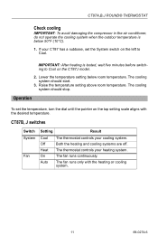
.... If the furnace shuts off before the set the system switch to the number that you could not find the anticipator setting on the thermostat cover. CT87A,B,J ROUND® THERMOSTAT 8 Set the heat anticipator for your type of system shown in Step 3, sub-step 3. NOTE: If ...the furnace stays on the setting scale is below .3 ampere. 9 Check heating/cooling operation Check heating 1. Turn the transparent ...
.... If the furnace shuts off before the set the system switch to the number that you could not find the anticipator setting on the thermostat cover. CT87A,B,J ROUND® THERMOSTAT 8 Set the heat anticipator for your type of system shown in Step 3, sub-step 3. NOTE: If ...the furnace stays on the setting scale is below .3 ampere. 9 Check heating/cooling operation Check heating 1. Turn the transparent ...
Installation Instructions
Page 11
... temperature. Heat On Auto The thermostat controls your cooling system. Both the heating and cooling systems are off. If your CT87 has a subbase, set the temperature, turn the dial until the pointer on the CT87J model. 2. The fan runs only with the desired temperature. Raise the temperature setting above room temperature. CT87A,B,J ROUND® THERMOSTAT Check cooling...
... temperature. Heat On Auto The thermostat controls your cooling system. Both the heating and cooling systems are off. If your CT87 has a subbase, set the temperature, turn the dial until the pointer on the CT87J model. 2. The fan runs only with the desired temperature. Raise the temperature setting above room temperature. CT87A,B,J ROUND® THERMOSTAT Check cooling...
Installation Instructions
Page 12
...02 Printed in the possession of a consumer. In Canada, write Retail Products ON15, Honeywell Limited/Honeywell Limitée, 35 Dynamic Drive, Scarborough, Ontario M1V 4Z9. Honeywell's sole responsibility shall be free from defects in the workmanship or materials, under normal use and service, for a ...purchase) and a short description of the malfunction, and mail it is shown by Honeywell that the defect or malfunction was in U.S.A. CT87A,B,J ROUND® THERMOSTAT Limited One-Year Warranty Honeywell warrants this product, excluding battery, to be to repair or replace the product ...
...02 Printed in the possession of a consumer. In Canada, write Retail Products ON15, Honeywell Limited/Honeywell Limitée, 35 Dynamic Drive, Scarborough, Ontario M1V 4Z9. Honeywell's sole responsibility shall be free from defects in the workmanship or materials, under normal use and service, for a ...purchase) and a short description of the malfunction, and mail it is shown by Honeywell that the defect or malfunction was in U.S.A. CT87A,B,J ROUND® THERMOSTAT Limited One-Year Warranty Honeywell warrants this product, excluding battery, to be to repair or replace the product ...


