
Installation Guide
Page 1
... unfamiliar with 2 • Installing the Ceiling Plate. Wiring o e electrical cable is secured to the joist or support brace by the support brace manufacturer). Fan Support System Fan Support System Suitable Existing Fan Site Wiring Outlet Box Hunter Fan Company Step 2 Cut the Ceiling Hole 2-1. Steps 2 - 3 Step 3 Install a Support Brace, If Necessary Determine if there is a ceiling joist directly above the floor and the ceiling is at least 8 feet high. • e fan blades have now successfully prepared...
... unfamiliar with 2 • Installing the Ceiling Plate. Wiring o e electrical cable is secured to the joist or support brace by the support brace manufacturer). Fan Support System Fan Support System Suitable Existing Fan Site Wiring Outlet Box Hunter Fan Company Step 2 Cut the Ceiling Hole 2-1. Steps 2 - 3 Step 3 Install a Support Brace, If Necessary Determine if there is a ceiling joist directly above the floor and the ceiling is at least 8 feet high. • e fan blades have now successfully prepared...

Owner's Manual
Page 1
Date Purchased Where Purchased Type 3 Models Owner's Guide and Installation Manual English Form# 42616-01 20100202 ©2010 Hunter Fan Co. Model Name Model No. For Your Records and Warranty Assistance For reference, also attach your receipt or a copy of your receipt to the manual.
Date Purchased Where Purchased Type 3 Models Owner's Guide and Installation Manual English Form# 42616-01 20100202 ©2010 Hunter Fan Co. Model Name Model No. For Your Records and Warranty Assistance For reference, also attach your receipt or a copy of your receipt to the manual.
Owner's Manual
Page 2
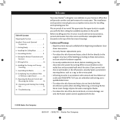
... 6 2 • Installing the Ceiling Plate 7 3 • Assembling the Fan 8 4 • Setting the Remote Transmitter and Receiver 9 5 • Wiring the Fan 10 6 • Installing the Canopy and Canopy Trim Ring 11 7 • Assembling the Blades 12 8 • Completing Your Installation With or Without a Light Fixture 13 9 • Operating the Remote Control and Mounting the Holder 16 10 • Operating and Cleaning Your Ceiling Fan 17 11 • Troubleshooting 18 Welcome Your new Hunter® ceiling fan is an addition to your fan, disconnect the power by turning...
... 6 2 • Installing the Ceiling Plate 7 3 • Assembling the Fan 8 4 • Setting the Remote Transmitter and Receiver 9 5 • Wiring the Fan 10 6 • Installing the Canopy and Canopy Trim Ring 11 7 • Assembling the Blades 12 8 • Completing Your Installation With or Without a Light Fixture 13 9 • Operating the Remote Control and Mounting the Holder 16 10 • Operating and Cleaning Your Ceiling Fan 17 11 • Troubleshooting 18 Welcome Your new Hunter® ceiling fan is an addition to your fan, disconnect the power by turning...
Owner's Manual
Page 3
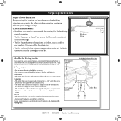
... your new Hunter fan. Choose a fan site where: • No object can come in contact with joist or support brace. • e bottom of the outlet box is directly below the joist or support brace. Fan Support System • Fan attaches directly to the joist or support brace by an approved connector. • Six inches of the fan. 30" From Wall or Nearest Obstruction 7' Minimum Blades to Floor 8' Minimum Ceiling...
... your new Hunter fan. Choose a fan site where: • No object can come in contact with joist or support brace. • e bottom of the outlet box is directly below the joist or support brace. Fan Support System • Fan attaches directly to the joist or support brace by an approved connector. • Six inches of the fan. 30" From Wall or Nearest Obstruction 7' Minimum Blades to Floor 8' Minimum Ceiling...
Owner's Manual
Page 4
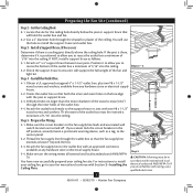
...; Hunter Fan Company Drill pilot holes no larger than the minor diameter of the wood screws (5/64") through the outlet box so that the fan supply line extends at any hardware store or electrical supply house. 4-2. Make certain the wiring meets all national and local standards and ANSI/NFPA 70. You have now successfully prepared your ceiling fan, go to install the support brace...
...; Hunter Fan Company Drill pilot holes no larger than the minor diameter of the wood screws (5/64") through the outlet box so that the fan supply line extends at any hardware store or electrical supply house. 4-2. Make certain the wiring meets all national and local standards and ANSI/NFPA 70. You have now successfully prepared your ceiling fan, go to install the support brace...
Owner's Manual
Page 5
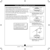
... and Optional Accessories Understanding Mounting and Installer's Choice® Hunter's patented 3-position mounting system provides you can install your Hunter fan in this manual include instructions for a vaulted or angled ceiling 5 42616-01 • 02/02/10 • Hunter Fan Company To install and use the accessories, follow the instructions included with each product. You can purchase Hunter extension downrods. Considering Optional Accessories Consider using Hunter's optional accessories, including a wall-mounted or remote speed control. Low Profile Mounting fits close to assure...
... and Optional Accessories Understanding Mounting and Installer's Choice® Hunter's patented 3-position mounting system provides you can install your Hunter fan in this manual include instructions for a vaulted or angled ceiling 5 42616-01 • 02/02/10 • Hunter Fan Company To install and use the accessories, follow the instructions included with each product. You can purchase Hunter extension downrods. Considering Optional Accessories Consider using Hunter's optional accessories, including a wall-mounted or remote speed control. Low Profile Mounting fits close to assure...
Owner's Manual
Page 6
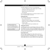
... the fan parts. If any shipping damage to a licensed installer or electrician. Proper ceiling fan location and attachment to the included Parts Guide. Installing Multiple Fans? Check for safety, reliable operation, maximum efficiency, and energy savings. 6 42616-01 • 02/02/10 • Hunter Fan Company If you to the motor or fan blades. If you begin installing the fan, follow all the instructions in ceiling. • Drill holes for installing the fan: • Electric drill...
... the fan parts. If any shipping damage to a licensed installer or electrician. Proper ceiling fan location and attachment to the included Parts Guide. Installing Multiple Fans? Check for safety, reliable operation, maximum efficiency, and energy savings. 6 42616-01 • 02/02/10 • Hunter Fan Company If you to the motor or fan blades. If you begin installing the fan, follow all the instructions in ceiling. • Drill holes for installing the fan: • Electric drill...
Owner's Manual
Page 7
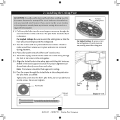
... to the outlet box and associated wall switch location. Flat Washer Toward Ceiling Peak For Angled Ceilings: Be sure to orient the ceiling plate so that the two tabs are pointing toward the ceiling peak. Place a flat washer on the screws. Note: The isolators should be flush against the ceiling. 2-6. 2 • Installing the Ceiling Plate CAUTION: To avoid possible electrical shock, before installing your fan, disconnect the power by turning off...
... to the outlet box and associated wall switch location. Flat Washer Toward Ceiling Peak For Angled Ceilings: Be sure to orient the ceiling plate so that the two tabs are pointing toward the ceiling peak. Place a flat washer on the screws. Note: The isolators should be flush against the ceiling. 2-6. 2 • Installing the Ceiling Plate CAUTION: To avoid possible electrical shock, before installing your fan, disconnect the power by turning off...
Owner's Manual
Page 8
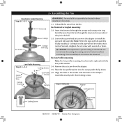
...Remove the set screw from the fan through the canopy and canopy trim ring. 3 • Assembling the Fan Standard or Angle Mounting Steps 3-2 - 3-3 Downrod Set Screw Canopy Canopy Trim Ring WARNING: Fan may fall if not assembled as directed in the adapter. For Low Profile mounting: Low Profile Mounting Steps 3-5 - 3-6 Locking Screws Note: For low profile mounting, the downrod is replaced with a wrench or pliers. Canopy Trim Ring Canopy Step 3-6 (Detail) Adapter Locking Screws Locking Screw Low Profile Washer 8 42616-01 • 02/02/10 • Hunter Fan Company...
...Remove the set screw from the fan through the canopy and canopy trim ring. 3 • Assembling the Fan Standard or Angle Mounting Steps 3-2 - 3-3 Downrod Set Screw Canopy Canopy Trim Ring WARNING: Fan may fall if not assembled as directed in the adapter. For Low Profile mounting: Low Profile Mounting Steps 3-5 - 3-6 Locking Screws Note: For low profile mounting, the downrod is replaced with a wrench or pliers. Canopy Trim Ring Canopy Step 3-6 (Detail) Adapter Locking Screws Locking Screw Low Profile Washer 8 42616-01 • 02/02/10 • Hunter Fan Company...
Owner's Manual
Page 9
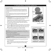
... to operate the fan with the hooks on the ceiling plate hooks. CAUTION: The remote control device complies with this equipment. Receiver DIP switches 4-1. Move the switch to the "INC" side if you are going to use incandescent bulbs. 4-3. Install the included 9-volt battery into the transmitter. IMPORTANT! Changes or modifications not expressly approved by Hunter Fan Company could void your authority to operate this fan. 4-4. WARNING: Use only the Hunter Fan speed control supplied with part...
... to operate the fan with the hooks on the ceiling plate hooks. CAUTION: The remote control device complies with this equipment. Receiver DIP switches 4-1. Move the switch to the "INC" side if you are going to use incandescent bulbs. 4-3. Install the included 9-volt battery into the transmitter. IMPORTANT! Changes or modifications not expressly approved by Hunter Fan Company could void your authority to operate this fan. 4-4. WARNING: Use only the Hunter Fan speed control supplied with part...

Owner's Manual
Page 10
... ceiling plate into the outlet box. 5-7. Using the small wire connectors, connect the wires from the fan as follows: • The white (common) power wire from the ceiling to the white wire from the receiver (marked on red tag "NEUTRAL IN") • The black power wire from the ceiling to make sure no bare wire or wire strands are unfamiliar with national and local electrical codes and ANSI/NFPA 70. Receiver Steps 5-3 - 5-7 Large Wire Connector Small Wire Connector...
... ceiling plate into the outlet box. 5-7. Using the small wire connectors, connect the wires from the fan as follows: • The white (common) power wire from the ceiling to the white wire from the receiver (marked on red tag "NEUTRAL IN") • The black power wire from the ceiling to make sure no bare wire or wire strands are unfamiliar with national and local electrical codes and ANSI/NFPA 70. Receiver Steps 5-3 - 5-7 Large Wire Connector Small Wire Connector...

Owner's Manual
Page 11
Swing the fan up to align the canopy screw holes with the screw holes aligned, partially install two canopy screws into place. Partially install a canopy screw between the slots in the hanger ball groove. When all the holes are still in the hanger ball. Step 6-1 Tab Groove Step 6-2 Step 6-3 Canopy Canopy Trim Ring 11 42616-01 • 02/02/10 • Hunter Fan Company Canopy Screw Note: Your fan may have multiple tabs and grooves that...
Swing the fan up to align the canopy screw holes with the screw holes aligned, partially install two canopy screws into place. Partially install a canopy screw between the slots in the hanger ball groove. When all the holes are still in the hanger ball. Step 6-1 Tab Groove Step 6-2 Step 6-3 Canopy Canopy Trim Ring 11 42616-01 • 02/02/10 • Hunter Fan Company Canopy Screw Note: Your fan may have multiple tabs and grooves that...

Owner's Manual
Page 12
... treated with grommet Blade Assembly Screws Step 7-4 Use without grommet 12 42616-01 • 02/02/10 • Hunter Fan Company Blade Mounting Screw If you used grommets, the blades may include blade grommets. For each blade to attract dust and dirt. Use a dry or slightly damp lint free cloth to secure shipping blocks. 7-4. Remove the blade mounting screws and rubber shipping bumpers from the motor. Step 7-1 (Detail) Grommet Note: The blades on the blades. 7-2. Do not use several styles of fan blade irons (brackets that...
... treated with grommet Blade Assembly Screws Step 7-4 Use without grommet 12 42616-01 • 02/02/10 • Hunter Fan Company Blade Mounting Screw If you used grommets, the blades may include blade grommets. For each blade to attract dust and dirt. Use a dry or slightly damp lint free cloth to secure shipping blocks. 7-4. Remove the blade mounting screws and rubber shipping bumpers from the motor. Step 7-1 (Detail) Grommet Note: The blades on the blades. 7-2. Do not use several styles of fan blade irons (brackets that...
Owner's Manual
Page 13
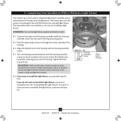
... optional switch housing cap and plug button. Feed the upper plug connector through the center opening of the keyhole slots. Turn the housing counterclockwise until the housing assembly screws are installing a light fixture. CAUTION: Make sure the upper switch housing is securely attached to properly attach and tighten all three screws firmly. 8 • Completing Your Installation With or Without a Light Fixture Your Hunter fan comes with this fan model. 8-1. Install the remaining screw into the switch housing mounting plate...
... optional switch housing cap and plug button. Feed the upper plug connector through the center opening of the keyhole slots. Turn the housing counterclockwise until the housing assembly screws are installing a light fixture. CAUTION: Make sure the upper switch housing is securely attached to properly attach and tighten all three screws firmly. 8 • Completing Your Installation With or Without a Light Fixture Your Hunter fan comes with this fan model. 8-1. Install the remaining screw into the switch housing mounting plate...

Owner's Manual
Page 14
... that limit or the specifications on the light socket may vary. To attach the lower switch housing, connect the upper plug connector from the motor to a maximum of lights may result in the upper and lower switch housings. Place the lower switch housing assembly over the upper switch housing. Shade Bulb Steps 8-8 - 8-10 14 42616-01 • 02/02/10 • Hunter Fan Company Plug Connector Upper Switch Housing Note: Both plug connectors are properly aligned before connecting them. Align the side screw holes...
... that limit or the specifications on the light socket may vary. To attach the lower switch housing, connect the upper plug connector from the motor to a maximum of lights may result in the upper and lower switch housings. Place the lower switch housing assembly over the upper switch housing. Shade Bulb Steps 8-8 - 8-10 14 42616-01 • 02/02/10 • Hunter Fan Company Plug Connector Upper Switch Housing Note: Both plug connectors are properly aligned before connecting them. Align the side screw holes...

Owner's Manual
Page 15
... the lower switch housing. Step 8-15 Light Fixture Screws Cap Plug Button Step 8-18 Male Dummy Terminal Female Dummy Terminal 15 42616-01 • 02/02/10 • Hunter Fan Company Remove the light fixture screws, then remove the light fixture. 8-16. Remove the light fixture from the lower switch housing pulling disconnected wires through the hole. 8-17. Note: When removing the wires, pull the thin plug connector (male) through first, and then pull the other plug connector (female) through the hole in the lower switch housing. 8-18. Install the...
... the lower switch housing. Step 8-15 Light Fixture Screws Cap Plug Button Step 8-18 Male Dummy Terminal Female Dummy Terminal 15 42616-01 • 02/02/10 • Hunter Fan Company Remove the light fixture screws, then remove the light fixture. 8-16. Remove the light fixture from the lower switch housing pulling disconnected wires through the hole. 8-17. Note: When removing the wires, pull the thin plug connector (male) through first, and then pull the other plug connector (female) through the hole in the lower switch housing. 8-18. Install the...

Owner's Manual
Page 16
...; Operating the Remote Control and Mounting the Holder 9-1. Fan Speed High Fan Speed Low Fan Speed Medium Fan Off Fan Light Steps 9-1 - 9-2 16 42616-01 • 02/02/10 • Hunter Fan Company Step 9-4 The light button turns the light. When necessary, replace the battery with the screws already in the switch plate. Push the light button again to the figure on the wall. Or, you can mount the remote holder to any toggle switch plate with a 9-volt alkaline battery. 9-4. Note: For best operation...
...; Operating the Remote Control and Mounting the Holder 9-1. Fan Speed High Fan Speed Low Fan Speed Medium Fan Off Fan Light Steps 9-1 - 9-2 16 42616-01 • 02/02/10 • Hunter Fan Company Step 9-4 The light button turns the light. When necessary, replace the battery with the screws already in the switch plate. Push the light button again to the figure on the wall. Or, you can mount the remote holder to any toggle switch plate with a 9-volt alkaline battery. 9-4. Note: For best operation...
Owner's Manual
Page 17
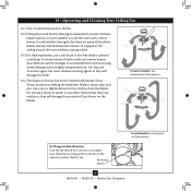
... air flow pattern In cold weather, use a soft brush or lint-free cloth to clean the blades. Reversing Switch 17 42616-01 • 02/02/10 • Hunter Fan Company A vacuum cleaner brush nozzle can remove heavier dust. Use a dry or slightly damp lint free cloth to prevent scratching. 10 • Operating and Cleaning Your Ceiling Fan 10-1.Turn on electrical power to the fan. 10-2.Ceiling fans work best by blowing air downward (counterclockwise blade...
... air flow pattern In cold weather, use a soft brush or lint-free cloth to clean the blades. Reversing Switch 17 42616-01 • 02/02/10 • Hunter Fan Company A vacuum cleaner brush nozzle can remove heavier dust. Use a dry or slightly damp lint free cloth to prevent scratching. 10 • Operating and Cleaning Your Ceiling Fan 10-1.Turn on electrical power to the fan. 10-2.Ceiling fans work best by blowing air downward (counterclockwise blade...

Owner's Manual
Page 18
... on , replace fuse, or reset breaker. 2. If so, replace all blade and/or blade iron screws. 3. Check and tighten the screws in the switch housing mounting plate and in the switch housing. 4. It is properly seated. Issue: Light shuts off , support fan very carefully, and check that the switch is secure. 6. Tighten the blade bracket screws until snug. 3. Federal regulations, this ceiling fan contains a wattage saver that the glass is engaged. 5. If you need parts or service assistance, please...
... on , replace fuse, or reset breaker. 2. If so, replace all blade and/or blade iron screws. 3. Check and tighten the screws in the switch housing mounting plate and in the switch housing. 4. It is properly seated. Issue: Light shuts off , support fan very carefully, and check that the switch is secure. 6. Tighten the blade bracket screws until snug. 3. Federal regulations, this ceiling fan contains a wattage saver that the glass is engaged. 5. If you need parts or service assistance, please...
Parts Guide
Page 1
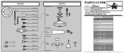
...FULL ASSEMBLY INSTRUCTIONS. If parts are included in the box. Parts List Item Name Hanging System Kit Ceiling Plate Canopy Canopy Trim Ring Hanger Ball / Downrod Assembly Setscrew Low Profile Washer Canopy Screw Wood Screw Wood Screw Flat Washer Mounting Isolator Screw, Low Profile Switch Housing Assembly Switch Housing Cover Switch Housing Plug Button Blade Iron Set Blade Set Screw, Blade Iron Armature Light Kit Assembly Light bulb / Bulb Hardware Kit Blade Grommet Blade Assembly Screw Screw, Machine, 6-32 Wire Connector Mounting Isolator Screw, Switch Housing Assembly Balancing Kit Remote...
...FULL ASSEMBLY INSTRUCTIONS. If parts are included in the box. Parts List Item Name Hanging System Kit Ceiling Plate Canopy Canopy Trim Ring Hanger Ball / Downrod Assembly Setscrew Low Profile Washer Canopy Screw Wood Screw Wood Screw Flat Washer Mounting Isolator Screw, Low Profile Switch Housing Assembly Switch Housing Cover Switch Housing Plug Button Blade Iron Set Blade Set Screw, Blade Iron Armature Light Kit Assembly Light bulb / Bulb Hardware Kit Blade Grommet Blade Assembly Screw Screw, Machine, 6-32 Wire Connector Mounting Isolator Screw, Switch Housing Assembly Balancing Kit Remote...


