
Installation Guide
Page 1
... box • Two #8 x 1-1/2" wood screws and washers • Approved connector for electrical wire Checklist for your new Hunter fan. Locate the site for safety, reliable operation, maximum efficiency, and energy savings. If the joist is there, determine if it to allow you are essential for the ceiling hole directly below the joist or support brace. For instructions to install your ceiling fan, go to your ceiling fan site. Ceiling Hole o e outlet box clearance hole...
... box • Two #8 x 1-1/2" wood screws and washers • Approved connector for electrical wire Checklist for your new Hunter fan. Locate the site for safety, reliable operation, maximum efficiency, and energy savings. If the joist is there, determine if it to allow you are essential for the ceiling hole directly below the joist or support brace. For instructions to install your ceiling fan, go to your ceiling fan site. Ceiling Hole o e outlet box clearance hole...

Owner's Manual
Page 1
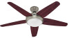
Date Purchased Where Purchased Type 3 Models Owner's Guide and Installation Manual English Español Form# 42797-01 20081113 ©2008 Hunter Fan Co. For Your Records and Warranty Assistance For reference, also attach your receipt or a copy of your receipt to the manual. _W_e_s_t_si_d_e__II Model Name _2_1_6_2_1 Model No.
Date Purchased Where Purchased Type 3 Models Owner's Guide and Installation Manual English Español Form# 42797-01 20081113 ©2008 Hunter Fan Co. For Your Records and Warranty Assistance For reference, also attach your receipt or a copy of your receipt to the manual. _W_e_s_t_si_d_e__II Model Name _2_1_6_2_1 Model No.

Owner's Manual
Page 2
... 4 2 • Installing the Ceiling Plate 5 3 • Assembling the Top Housing 6 4 • Assembling and Hanging the Fan . . . . 7 5 • Setting the Remote Transmitter and Receiver 8 6 • Wiring the Fan 9 7 • Installing the Canopy 11 8 • Assembling the Blades 12 9 • Completing Your Installation 13 10 • Operating the Remote Control and Mounting the Holder 14 11 • Operating and Cleaning Your Ceiling Fan 15 12 • Troubleshooting 16 Welcome Your new Hunter® ceiling fan is an addition to the service panel. • All wiring must...
... 4 2 • Installing the Ceiling Plate 5 3 • Assembling the Top Housing 6 4 • Assembling and Hanging the Fan . . . . 7 5 • Setting the Remote Transmitter and Receiver 8 6 • Wiring the Fan 9 7 • Installing the Canopy 11 8 • Assembling the Blades 12 9 • Completing Your Installation 13 10 • Operating the Remote Control and Mounting the Holder 14 11 • Operating and Cleaning Your Ceiling Fan 15 12 • Troubleshooting 16 Welcome Your new Hunter® ceiling fan is an addition to the service panel. • All wiring must...
Owner's Manual
Page 3
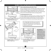
... Optional Accessories Consider using Hunter's optional accessories, including a wall-mounted or remote speed control. To install and use sturdy 3/4 in. All Hunter fans use the accessories, follow the instructions included with each product. You can purchase Hunter extension downrods. diameter pipe to these instructions, and use only Hunter speed controls. The steps in one of three ways, depending on ceiling height and your Hunter fan, use only the hardware supplied. 3 42797-01 • 11/13/08 • Hunter Fan Company Understanding Mounting and Installer...
... Optional Accessories Consider using Hunter's optional accessories, including a wall-mounted or remote speed control. To install and use sturdy 3/4 in. All Hunter fans use the accessories, follow the instructions included with each product. You can purchase Hunter extension downrods. diameter pipe to these instructions, and use only Hunter speed controls. The steps in one of three ways, depending on ceiling height and your Hunter fan, use only the hardware supplied. 3 42797-01 • 11/13/08 • Hunter Fan Company Understanding Mounting and Installer...
Owner's Manual
Page 4
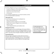
... one fan, keep the fan blades and blade irons (if applicable) in ceiling. • Drill holes for and install wood screws. • Identify and connect electrical wires. • Lift 40 pounds. 1 • Getting Ready To install a ceiling fan, be sure you can direct you to the building structure are essential for safety, reliable operation, maximum efficiency, and energy savings. Refer to the motor or fan blades. Check for any parts are...
... one fan, keep the fan blades and blade irons (if applicable) in ceiling. • Drill holes for and install wood screws. • Identify and connect electrical wires. • Lift 40 pounds. 1 • Getting Ready To install a ceiling fan, be sure you can direct you to the building structure are essential for safety, reliable operation, maximum efficiency, and energy savings. Refer to the motor or fan blades. Check for any parts are...
Owner's Manual
Page 5
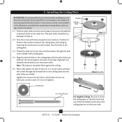
... noise isolators ("Isolators"). Tighten the screws into the wood support structure through the outermost holes in the off the circuit breakers to the outlet box and associated wall switch location. If you drilled. wood screws and pass the screws through the hole in the middle of 9/64 in . Isolator Ceiling Plate Flat Washer Step 2-2 Steps 2-3 - 2-5 3 in the ceiling plate are on the screws. pilot holes; 2 • Installing the Ceiling Plate CAUTION: To avoid possible electrical...
... noise isolators ("Isolators"). Tighten the screws into the wood support structure through the outermost holes in the off the circuit breakers to the outlet box and associated wall switch location. If you drilled. wood screws and pass the screws through the hole in the middle of 9/64 in . Isolator Ceiling Plate Flat Washer Step 2-2 Steps 2-3 - 2-5 3 in the ceiling plate are on the screws. pilot holes; 2 • Installing the Ceiling Plate CAUTION: To avoid possible electrical...

Owner's Manual
Page 6
Steps 3-1 - 3-2 Assembly Screw Top Housing Hanger Adapter 6 42797-01 • 11/13/08 • Hunter Fan Company Make certain the housing sits flat on the hanger adapter with the three narrow notches in the top housing. Install three (3) assembly screws and tighten them securely. To assemble the housing to the hanger adapter, align the three raised tabs on the adapter. 3-2. 3 • Assembling the Top Housing 3-1.
Steps 3-1 - 3-2 Assembly Screw Top Housing Hanger Adapter 6 42797-01 • 11/13/08 • Hunter Fan Company Make certain the housing sits flat on the hanger adapter with the three narrow notches in the top housing. Install three (3) assembly screws and tighten them securely. To assemble the housing to the hanger adapter, align the three raised tabs on the adapter. 3-2. 3 • Assembling the Top Housing 3-1.
Owner's Manual
Page 7
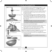
... mounting (steps 4-1 - 4-2) or for low profile mounting (steps 4-3 - 4-5). Note: For low profile mounting, the downrod is fully installed, 2-3 threads on the threads. WARNING: Fan may fall if not assembled as directed in the hanger ball. 4-6. Round Hole 7 42797-01 • 11/13/08 • Hunter Fan Company Loosen the square head set screw from the bottom of the canopy and the two grooves in these installation instructions. Securely retighten the set screw with the low profile washer...
... mounting (steps 4-1 - 4-2) or for low profile mounting (steps 4-3 - 4-5). Note: For low profile mounting, the downrod is fully installed, 2-3 threads on the threads. WARNING: Fan may fall if not assembled as directed in the hanger ball. 4-6. Round Hole 7 42797-01 • 11/13/08 • Hunter Fan Company Loosen the square head set screw from the bottom of the canopy and the two grooves in these installation instructions. Securely retighten the set screw with the low profile washer...
Owner's Manual
Page 8
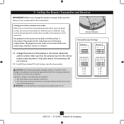
... of the jumpers in the remote receiver and transmitter. Change the position of the receiver. This device may cause undesired operation. 5 • Setting the Remote Transmitter and Receiver IMPORTANT! you may desire to a different code, so that the operation of one fan does not affect the operation of pliers or tweezers. 5-1. CAUTION: The remote control device complies with this equipment. Changes or modifications not expressly approved by Hunter Fan Company could...
... of the jumpers in the remote receiver and transmitter. Change the position of the receiver. This device may cause undesired operation. 5 • Setting the Remote Transmitter and Receiver IMPORTANT! you may desire to a different code, so that the operation of one fan does not affect the operation of pliers or tweezers. 5-1. CAUTION: The remote control device complies with this equipment. Changes or modifications not expressly approved by Hunter Fan Company could...

Owner's Manual
Page 9
... wire from the receiver. • Connect the red wire from the fan to the red wire from the receiver. • Connect the black wire with a white stripe from the top of the receiver are not included. Place the receiver in the ceiling plate. 6-5. Disconnect the power by turning off the circuit breakers to the outlet box and associated wall switch location. 6-2. To connect the wires, hold the bare metal leads together and place a wire connector...
... wire from the receiver. • Connect the red wire from the fan to the red wire from the receiver. • Connect the black wire with a white stripe from the top of the receiver are not included. Place the receiver in the ceiling plate. 6-5. Disconnect the power by turning off the circuit breakers to the outlet box and associated wall switch location. 6-2. To connect the wires, hold the bare metal leads together and place a wire connector...

Owner's Manual
Page 10
... white wire from the ceiling. • Connect the black wire from the receiver to the ground wire from the other wires. 10 42797-01 • 11/13/08 • Hunter Fan Company Place the green and white wires on a separate side of the canopy.) 6-8. Connect the green ground wires from the ceiling plate and the downrod to the black wire from the receiver through the ceiling plate hole into the outlet box. 6 • Wiring the Fan (Continued...
... white wire from the ceiling. • Connect the black wire from the receiver to the ground wire from the other wires. 10 42797-01 • 11/13/08 • Hunter Fan Company Place the green and white wires on a separate side of the canopy.) 6-8. Connect the green ground wires from the ceiling plate and the downrod to the black wire from the receiver through the ceiling plate hole into the outlet box. 6 • Wiring the Fan (Continued...
Owner's Manual
Page 11
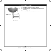
Insert and tighten the mounting screws securely. Canopy Mounting Screw 11 42797-01 • 11/13/08 • Hunter Fan Company Align the holes in the canopy with the mounting holes on the ceiling plate. 7-3. Holding the canopy, raise the fan off the hook. 7-2. Steps 7-1- 7-3 7 • Installing the Canopy 7-1.
Insert and tighten the mounting screws securely. Canopy Mounting Screw 11 42797-01 • 11/13/08 • Hunter Fan Company Align the holes in the canopy with the mounting holes on the ceiling plate. 7-3. Holding the canopy, raise the fan off the hook. 7-2. Steps 7-1- 7-3 7 • Installing the Canopy 7-1.

Owner's Manual
Page 12
Slide flat washers onto the shafts of the blade assembly screws. 8-3. Step 8-1 Blade Assembly Screw Step 8-2 Flat Washer 12 42797-01 • 11/13/08 • Hunter Fan Company Align the holes on the blade with the holes in the fan motor. 8-2. Attach the blade to the motor using the blade assembly screws. 8-4. Repeat for each blade. Insert blade into slot. 3 • Assembling tbe Blades Fan Motor Holes 8 • Assembling the Blades 8-1.
Slide flat washers onto the shafts of the blade assembly screws. 8-3. Step 8-1 Blade Assembly Screw Step 8-2 Flat Washer 12 42797-01 • 11/13/08 • Hunter Fan Company Align the holes on the blade with the holes in the fan motor. 8-2. Attach the blade to the motor using the blade assembly screws. 8-4. Repeat for each blade. Insert blade into slot. 3 • Assembling tbe Blades Fan Motor Holes 8 • Assembling the Blades 8-1.

Owner's Manual
Page 13
... plug connector from the ballast to the fluorescent bulb. 9-9. Partially install two light kit fitter screws into the light kit mounting plate. 9-2. Steps 9-1 - 9-8 Light Kit Fitter Fluorescent Bulb Globe Trim Band Step 9-9 Ballast Glass Globe 13 42797-01 • 11/13/08 • Hunter Fan Company Connect the 2-pin plug connector from the ballast. 9-6. Align the three holes in the trim band with two ballast screws. 9-7. Connect the 4 pin plug from the fan through the light kit fitter. 9-3. Securely tighten all three screws. Install...
... plug connector from the ballast to the fluorescent bulb. 9-9. Partially install two light kit fitter screws into the light kit mounting plate. 9-2. Steps 9-1 - 9-8 Light Kit Fitter Fluorescent Bulb Globe Trim Band Step 9-9 Ballast Glass Globe 13 42797-01 • 11/13/08 • Hunter Fan Company Connect the 2-pin plug connector from the ballast. 9-6. Align the three holes in the trim band with two ballast screws. 9-7. Connect the 4 pin plug from the fan through the light kit fitter. 9-3. Securely tighten all three screws. Install...

Owner's Manual
Page 14
... any toggle switch plate with the remote control transmitter. The light button turns the light on the wall. 10-7.This product includes one 12-volt type 23A, MN-21 battery for turning the fan off and on and controlling the light and fan speed. 10-2. 10 • Operating the Remote Control and Mounting the Holder Reversing Switch Fan Speed High Fan Speed Low Steps 10-1 - 10-5 10-1. The remote transmitter has individual buttons for use with the screws already in the switch plate.
... any toggle switch plate with the remote control transmitter. The light button turns the light on the wall. 10-7.This product includes one 12-volt type 23A, MN-21 battery for turning the fan off and on and controlling the light and fan speed. 10-2. 10 • Operating the Remote Control and Mounting the Holder Reversing Switch Fan Speed High Fan Speed Low Steps 10-1 - 10-5 10-1. The remote transmitter has individual buttons for use with the screws already in the switch plate.

Owner's Manual
Page 15
... the fan finish. Press the remote control's HIGH speed button. If the remote control will turn on at the main electrical panel and turn the wall switch OFF. 11-3. Occasionally, apply a light coat of furniture polish for 5 days or more, turn on the light without causing a draft. 11-4. The fan should turn on the wall switch. Restore power at maximum brightness. 11-2. For cleaning finishes, use a soft brush or...
... the fan finish. Press the remote control's HIGH speed button. If the remote control will turn on at the main electrical panel and turn the wall switch OFF. 11-3. Occasionally, apply a light coat of furniture polish for 5 days or more, turn on the light without causing a draft. 11-4. The fan should turn on the wall switch. Restore power at maximum brightness. 11-2. For cleaning finishes, use a soft brush or...
Owner's Manual
Page 16
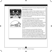
... bills. * On average at low speed settings. Your new ceiling fan has earned the ENERGY STAR label because it meets high energy efficiency specifications set by a Hunter ceiling fan lets you are doing your part to protect the environment. Beat the High Cost of Cooling The air movement created by the Environmental Protection Agency (EPA). Hunter fans have more efficient fan motors and air delivery due to more than typical ceiling fan models.
... bills. * On average at low speed settings. Your new ceiling fan has earned the ENERGY STAR label because it meets high energy efficiency specifications set by a Hunter ceiling fan lets you are doing your part to protect the environment. Beat the High Cost of Cooling The air movement created by the Environmental Protection Agency (EPA). Hunter fans have more efficient fan motors and air delivery due to more than typical ceiling fan models.
Owner's Manual
Page 17
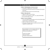
... blades. 3. Loosen canopy, check all connections according to balance the fan. 2. If you need parts or service assistance, please call 888‑830‑1326 or visit us at our Web site at http://www.hunterfan.com. fan does not move. 1. Tighten the blade screws until snug. 2. Check the plug connection in the switch housing. If your fan wobbles when operating, use the enclosed balancing kit and instructions to the wiring...
... blades. 3. Loosen canopy, check all connections according to balance the fan. 2. If you need parts or service assistance, please call 888‑830‑1326 or visit us at our Web site at http://www.hunterfan.com. fan does not move. 1. Tighten the blade screws until snug. 2. Check the plug connection in the switch housing. If your fan wobbles when operating, use the enclosed balancing kit and instructions to the wiring...
Parts Guide
Page 1
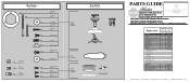
... MANUAL FOR FULL ASSEMBLY INSTRUCTIONS. If parts are included in . THIS PARTS GUIDE IS FOR REFERENCE ONLY. Wood Screw Flat Washer 1.5 in. Parts List Item Name Ceiling Plate Canopy Hanger Ball / Downrod Assembly Housing, Top Light Kit Assembly Globe/Shade Light bulb / Bulb Globe Trim Ring Blade Set Hardware Kit Washer, Installers Choice Screw, #6-32X.500 Canopy Screw Screw, Low Profile Wood Screw Blade Assembly Screw Flat Washer Screw, Machine, 6-32 Wire Connector Mounting Isolator Balancing Kit Ballast Remote Control Receiver Remote Control Transmitter Remote Control Cradle Model # 21621...
... MANUAL FOR FULL ASSEMBLY INSTRUCTIONS. If parts are included in . THIS PARTS GUIDE IS FOR REFERENCE ONLY. Wood Screw Flat Washer 1.5 in. Parts List Item Name Ceiling Plate Canopy Hanger Ball / Downrod Assembly Housing, Top Light Kit Assembly Globe/Shade Light bulb / Bulb Globe Trim Ring Blade Set Hardware Kit Washer, Installers Choice Screw, #6-32X.500 Canopy Screw Screw, Low Profile Wood Screw Blade Assembly Screw Flat Washer Screw, Machine, 6-32 Wire Connector Mounting Isolator Balancing Kit Ballast Remote Control Receiver Remote Control Transmitter Remote Control Cradle Model # 21621...


