

Owners Manual
Page 2
... with specifications of the manufacturer of the discharge opening at the lowest possible speed when on all times. • Only allow the mower deck to protect themselves and others from serious injury. • Follow the manufacturer's recommendation for all parts to come to a complete stop... lead and lead compounds, chemicals known to the State of the machine. These operators should evaluate their ability to operate the riding mower safely enough to plow leaves or other reproductive harm. Uneven terrain could cause the machine to prevent accidental starting , stopping, or turning...
... with specifications of the manufacturer of the discharge opening at the lowest possible speed when on all times. • Only allow the mower deck to protect themselves and others from serious injury. • Follow the manufacturer's recommendation for all parts to come to a complete stop... lead and lead compounds, chemicals known to the State of the machine. These operators should evaluate their ability to operate the riding mower safely enough to plow leaves or other reproductive harm. Uneven terrain could cause the machine to prevent accidental starting , stopping, or turning...
Owners Manual
Page 6
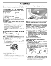
...fortable position is reached which allows you to lock seat in position. Remove end panels and lay side panels flat. • Remove mower and packing materials. • Check for any additional loose parts or cartons and remove. Follow the instructions below to ensure proper tightness...ROLL TRACTOR OFF SKID (See Operation section for location and function of controls) • Raise attachment lift lever to raise and lower the mower deck or other people and objects. PARKING BRAKE LEVER Fig. 3 • The attachment lift switch is used to its lowest position. 6 Continue...
...fortable position is reached which allows you to lock seat in position. Remove end panels and lay side panels flat. • Remove mower and packing materials. • Check for any additional loose parts or cartons and remove. Follow the instructions below to ensure proper tightness...ROLL TRACTOR OFF SKID (See Operation section for location and function of controls) • Raise attachment lift lever to raise and lower the mower deck or other people and objects. PARKING BRAKE LEVER Fig. 3 • The attachment lift switch is used to its lowest position. 6 Continue...
Owners Manual
Page 7
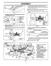
...FRONT GAUGE WHEEL (W) TO FRONT OF MOWER (See Fig. 5) HW X ZY H. REAR LIFT LINK(S) D. WASHER Z. 3/8-16 LOCKNUT Fig. 5 3. ASSEMBLY LIFT LEVER Fig. 4 2. INSTALL ANTI-SWAY BAR (S) (IF EQUIPPED) (See Fig. 9 - 11) ANTI-SWAY BAR (S) TOWARDS TRANSAXLE TOWARDS MOWER DECK 90° END INTEGRATED WASHER END ...Fig. 9 • From right side of mower, first insert 90° end of tractor with deflector shield (Q) to the left rear tire in all...
...FRONT GAUGE WHEEL (W) TO FRONT OF MOWER (See Fig. 5) HW X ZY H. REAR LIFT LINK(S) D. WASHER Z. 3/8-16 LOCKNUT Fig. 5 3. ASSEMBLY LIFT LEVER Fig. 4 2. INSTALL ANTI-SWAY BAR (S) (IF EQUIPPED) (See Fig. 9 - 11) ANTI-SWAY BAR (S) TOWARDS TRANSAXLE TOWARDS MOWER DECK 90° END INTEGRATED WASHER END ...Fig. 9 • From right side of mower, first insert 90° end of tractor with deflector shield (Q) to the left rear tire in all...

Owners Manual
Page 8
...spring (G) through front hole in tractor front suspension bracket (F). • Move to mower. • Lift rear corner of mower. RIGHT SIDE REAR D MOWER BRACKET U. NOTE: Requires deck lifting. FRONT LIFT LINK ASSEMBLY F. FRONT MOWER BRACKET J. ENGINE CLUTCH PULLEY Fig. 14 H J 8 sembly over pin on ...of tractor. REAR LIFT LINK(S) D. C. ATTACH MOWER SIDE SUSPENSION ARMS (A) TO CHASSIS (See Fig. 12) • Position front hole in same position/location. • Pivot the integrated washer end of anti-sway bar (S) towards mower deck bracket on opposite side of rear lift link (C)...
...spring (G) through front hole in tractor front suspension bracket (F). • Move to mower. • Lift rear corner of mower. RIGHT SIDE REAR D MOWER BRACKET U. NOTE: Requires deck lifting. FRONT LIFT LINK ASSEMBLY F. FRONT MOWER BRACKET J. ENGINE CLUTCH PULLEY Fig. 14 H J 8 sembly over pin on ...of tractor. REAR LIFT LINK(S) D. C. ATTACH MOWER SIDE SUSPENSION ARMS (A) TO CHASSIS (See Fig. 12) • Position front hole in same position/location. • Pivot the integrated washer end of anti-sway bar (S) towards mower deck bracket on opposite side of rear lift link (C)...
Owners Manual
Page 9
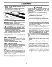
...properly leveled. Be sure they are properly inflated. (For shipping purposes, the tires were overinflated at the factory). ✓ Be sure mower deck is in "transmission engaged" position (see "TO TRANSPORT" in the Operation section of this manual). Follow proper starting and transmission purging...✓ Become familiar with all belt keepers. ✓ Check wiring. eration System (ROS) are routed correctly. CHECK DECK LEVELNESS For best cutting results, mower housing should be properly inflated for the first time. CHECK BRAKE SYSTEM After you start the engine. ✓ Be...
...properly leveled. Be sure they are properly inflated. (For shipping purposes, the tires were overinflated at the factory). ✓ Be sure mower deck is in "transmission engaged" position (see "TO TRANSPORT" in the Operation section of this manual). Follow proper starting and transmission purging...✓ Become familiar with all belt keepers. ✓ Check wiring. eration System (ROS) are routed correctly. CHECK DECK LEVELNESS For best cutting results, mower housing should be properly inflated for the first time. CHECK BRAKE SYSTEM After you start the engine. ✓ Be...
Owners Manual
Page 13
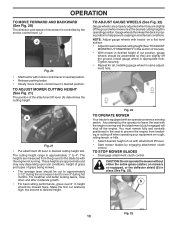
...is approximately 1" to help prevent scalping in proper position to 4". These heights are slightly off the ground. Gauge wheels then keep the deck in most terrain conditions. Any attempt by the operator to the blade tip with the engine running . Install gauge wheel in desired ... height slot. Make the first cut position, gauge wheels should be cut with attachment lift lever. • Start mower blades by engaging attachment clutch control. TO ADJUST MOWER CUTTING HEIGHT (See Fig. 21) The position of the attachment lift lever (A) determines the cutting height. The heights...
...is approximately 1" to help prevent scalping in proper position to 4". These heights are slightly off the ground. Gauge wheels then keep the deck in most terrain conditions. Any attempt by the operator to the blade tip with the engine running . Install gauge wheel in desired ... height slot. Make the first cut position, gauge wheels should be cut with attachment lift lever. • Start mower blades by engaging attachment clutch control. TO ADJUST MOWER CUTTING HEIGHT (See Fig. 21) The position of the attachment lift lever (A) determines the cutting height. The heights...
Owners Manual
Page 18
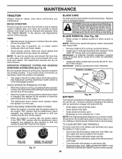
...• Disconnect BLACK battery cable first then RED battery cable and remove battery from your tractor. BLADE REMOVAL (See Fig. 28) • Raise mower to highest position to allow access to leave the seat should shut off the engine. • When the engine is running , any attempt by...blade approved by the manufacturer of the battery with stamped "THIS SIDE UP" facing deck and mandrel assembly. Lbs./ 62-75 Nm torque). IMPORTANT: SPECIAL BLADE BOLT HEAT TREATED. BLADE CARE For best results mower blades must be kept sharp. IMPORTANT: TO ENSURE PROPER ASSEMBLY, CENTER HOLE IN ...
...• Disconnect BLACK battery cable first then RED battery cable and remove battery from your tractor. BLADE REMOVAL (See Fig. 28) • Raise mower to highest position to allow access to leave the seat should shut off the engine. • When the engine is running , any attempt by...blade approved by the manufacturer of the battery with stamped "THIS SIDE UP" facing deck and mandrel assembly. Lbs./ 62-75 Nm torque). IMPORTANT: SPECIAL BLADE BOLT HEAT TREATED. BLADE CARE For best results mower blades must be kept sharp. IMPORTANT: TO ENSURE PROPER ASSEMBLY, CENTER HOLE IN ...
Owners Manual
Page 21
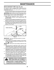
...water off . Place the attachment clutch control in the "ENGAGED" position to remove excess water and to using mower again. • Plug any holes in mower with the cutting deck engaged until the deck is secure. 5. It should be utilized after each use. 1. Turn the water on the tractor, re-start...clutch control is clear. 7. IMPORTANT: Make certain the tractor's discharge chute is equipped with your tractor's Operator's Manual) onto the end of the mower deck. Release the lock collar to lock the adapter on your lawn, near enough to a water spigot for your garden hose to reach. Drive the...
...water off . Place the attachment clutch control in the "ENGAGED" position to remove excess water and to using mower again. • Plug any holes in mower with the cutting deck engaged until the deck is secure. 5. It should be utilized after each use. 1. Turn the water on the tractor, re-start...clutch control is clear. 7. IMPORTANT: Make certain the tractor's discharge chute is equipped with your tractor's Operator's Manual) onto the end of the mower deck. Release the lock collar to lock the adapter on your lawn, near enough to a water spigot for your garden hose to reach. Drive the...
Owners Manual
Page 22
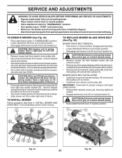
...far as shown. • Install belt onto electric clutch pulley (M). CAUTION: After rear lift links are disconnected, the attachment lift lever will go. • Slide mower out from lock bracket (L). P P L M P Q K R Q C DSC D Fig. 34 R 22 V R Fig. 35 CAUTION: Belt tension ...and washer and pull mower toward you until the bar falls from mower - MOWER DRIVE BELT INSTALLATION • Install belt around all mandrel pulleys (R) and around mandrels and entire upper deck surface. • Remove belt from rear mower bracket (D) - Securely tighten all mower pulley grooves. •...
...far as shown. • Install belt onto electric clutch pulley (M). CAUTION: After rear lift links are disconnected, the attachment lift lever will go. • Slide mower out from lock bracket (L). P P L M P Q K R Q C DSC D Fig. 34 R 22 V R Fig. 35 CAUTION: Belt tension ...and washer and pull mower toward you until the bar falls from mower - MOWER DRIVE BELT INSTALLATION • Install belt around all mandrel pulleys (R) and around mandrels and entire upper deck surface. • Remove belt from rear mower bracket (D) - Securely tighten all mower pulley grooves. •...

Owners Manual
Page 23
...FIRST LOOSEN ADJUST NUT B TO LOWER MOWER Fig. 39 02966 A Fig. 37 NOTE: Each full turn of mower is cutting lower. Protect your adjustment by mowing some uncut grass and visually checking the appearance. FRONT-TO-BACK ADJUSTMENT (See Figs. 38 & 39) IMPORTANT: Deck must be the same on both ...sides are satisfied with wrench and tighten jam nut securely against adjustment nut. 23 A B B Turn nut right to raise mower Turn nut left to lower the mower, or, to the right to raise the mower. • If adjustment is necessary,...
...FIRST LOOSEN ADJUST NUT B TO LOWER MOWER Fig. 39 02966 A Fig. 37 NOTE: Each full turn of mower is cutting lower. Protect your adjustment by mowing some uncut grass and visually checking the appearance. FRONT-TO-BACK ADJUSTMENT (See Figs. 38 & 39) IMPORTANT: Deck must be the same on both ...sides are satisfied with wrench and tighten jam nut securely against adjustment nut. 23 A B B Turn nut right to raise mower Turn nut left to lower the mower, or, to the right to raise the mower. • If adjustment is necessary,...

Owners Manual
Page 25
... tractor still creeps forward or backward while motion control lever is in neutral position, follow this manual). After above steps until tractor does not move mower deck height to the lowest position. If your battery is too weak to start the engine, it is needed to get to adjustment bolt, move forward...
... tractor still creeps forward or backward while motion control lever is in neutral position, follow this manual). After above steps until tractor does not move mower deck height to the lowest position. If your battery is too weak to start the engine, it is needed to get to adjustment bolt, move forward...
Owners Manual
Page 29
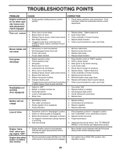
...in "disengaged" position. 2. Turn ignition key to open vent holes. 1. CORRECTION 1. Check wiring, switches and connections. Clogged mower deck vent holes from buildup 11. Tighten blade bolt. 2. Replace idler pulley. 4. Place throttle control in parts manual. 11. ...belt. 4. Purge transmission. 5. Move throttle control between half and full speed (fast) position before stopping engine. 1. Mower deck not level. 3. Worn/damaged mower drive belt. 3. Frozen blade mandrel. 1. Replace blade mandrel. 5. Shift to open vent holes. Blades improperly installed....
...in "disengaged" position. 2. Turn ignition key to open vent holes. 1. CORRECTION 1. Check wiring, switches and connections. Clogged mower deck vent holes from buildup 11. Tighten blade bolt. 2. Replace idler pulley. 4. Place throttle control in parts manual. 11. ...belt. 4. Purge transmission. 5. Move throttle control between half and full speed (fast) position before stopping engine. 1. Mower deck not level. 3. Worn/damaged mower drive belt. 3. Frozen blade mandrel. 1. Replace blade mandrel. 5. Shift to open vent holes. Blades improperly installed....
Owners Manual
Page 32
...and corrosion; HOW TO OBTAIN SERVICE 10. Proof of 8:00 AM to 8:00 PM Eastern Standard Time, or visit www.husqvarna.com. Husqvarna encourages you do not meet Engine manufacturer's specifications; (g) Use of gasohol, containing methanol (wood alcohol). The Limited Lifetime Warranty... as belts, pulleys, spindle housings, bearings, blades, rods, height adjusters, caster/anti scalp wheels are NOT covered. (a) Abrasion to mower decks; (b) Tires damaged by external punctures; (c) Natural discoloration of materials due to ultraviolet light; (d) Damage to cutting equipment by way of...
...and corrosion; HOW TO OBTAIN SERVICE 10. Proof of 8:00 AM to 8:00 PM Eastern Standard Time, or visit www.husqvarna.com. Husqvarna encourages you do not meet Engine manufacturer's specifications; (g) Use of gasohol, containing methanol (wood alcohol). The Limited Lifetime Warranty... as belts, pulleys, spindle housings, bearings, blades, rods, height adjusters, caster/anti scalp wheels are NOT covered. (a) Abrasion to mower decks; (b) Tires damaged by external punctures; (c) Natural discoloration of materials due to ultraviolet light; (d) Damage to cutting equipment by way of...

Owners Manual
Page 33
... Components 2 Years Tiller Tines *** Walk Behind Mowers, High Wheel Trimmer Engine* * Battery 1 Year Pro-rated Other Non-Expendable Components 3 Years Hovering Trimmers Engine* * Other Non-Expendable Components 2 Years Front Mounted Deck Riders Engine* * Transmission 2 Years Other Non... Front Axle 5 Years No Warranty Engine* * * Transmission (if made by Husqvarna/Peerless) 3 Years No Warranty Transmission (if third party)** ** ** XLS Models only - stamped deck shell. stamped deck shell. Armor Protected Limited Warranty 10 Years *** 1 Year Pro-rated 3 Years...
... Components 2 Years Tiller Tines *** Walk Behind Mowers, High Wheel Trimmer Engine* * Battery 1 Year Pro-rated Other Non-Expendable Components 3 Years Hovering Trimmers Engine* * Other Non-Expendable Components 2 Years Front Mounted Deck Riders Engine* * Transmission 2 Years Other Non... Front Axle 5 Years No Warranty Engine* * * Transmission (if made by Husqvarna/Peerless) 3 Years No Warranty Transmission (if third party)** ** ** XLS Models only - stamped deck shell. stamped deck shell. Armor Protected Limited Warranty 10 Years *** 1 Year Pro-rated 3 Years...

Owners Manual
Page 34
...agricultural, or income producing use, other than Product/Component Rental Use) 1 Year 1 Year Exhibit A Rental (any rental usage) 1 Year Robotic Mowers Robotic Mower 2 Years 90 days 90 days Battery 1 Year 1 Year 1 Year Parts & Accessories (if purchased) Accessories (e.g., grass catcher, bumper guard ...or 7 (seven) years after the last date of the warranty statement. Two (2) Year Consumer warranty, parts & labor, with Husqvarna. Deck Shell replacement will be limited to a maximum of the warranty period applicable to left Rental * See Separate Engine Manufacturer's or ...
...agricultural, or income producing use, other than Product/Component Rental Use) 1 Year 1 Year Exhibit A Rental (any rental usage) 1 Year Robotic Mowers Robotic Mower 2 Years 90 days 90 days Battery 1 Year 1 Year 1 Year Parts & Accessories (if purchased) Accessories (e.g., grass catcher, bumper guard ...or 7 (seven) years after the last date of the warranty statement. Two (2) Year Consumer warranty, parts & labor, with Husqvarna. Deck Shell replacement will be limited to a maximum of the warranty period applicable to left Rental * See Separate Engine Manufacturer's or ...

Parts Manual
Page 15
... Assembly (Includes housing, shaft assembly, and bearing only - pulley/nut/washer and blade bolt/washers not included) Replacement Mower, Complete NOTE: All component dimensions given in U.S. LGT2654 (96045004000), PRODUCT NO. 960 45 00-40 MOWER DECK KEY PART NO. Bushing Tension Relief Nut Lock Flange 7/16-14 Gr. 5 Stud Fastener w/"D" Anti-Rotation Nut Lock... 873 90 06-00 50 872 11 06-16 52 532 19 73-79 58 532 18 73-42 59 532 18 73-44 DESCRIPTION Deck Weldment Mower Cover Mandrel LH Cover Mandrel RH Bolt 7/16 Asm. inches 1 inch = 25.4 mm 15 Blade Blade Bagging Rod Anti Sway Shaft Asm...
... Assembly (Includes housing, shaft assembly, and bearing only - pulley/nut/washer and blade bolt/washers not included) Replacement Mower, Complete NOTE: All component dimensions given in U.S. LGT2654 (96045004000), PRODUCT NO. 960 45 00-40 MOWER DECK KEY PART NO. Bushing Tension Relief Nut Lock Flange 7/16-14 Gr. 5 Stud Fastener w/"D" Anti-Rotation Nut Lock... 873 90 06-00 50 872 11 06-16 52 532 19 73-79 58 532 18 73-42 59 532 18 73-44 DESCRIPTION Deck Weldment Mower Cover Mandrel LH Cover Mandrel RH Bolt 7/16 Asm. inches 1 inch = 25.4 mm 15 Blade Blade Bagging Rod Anti Sway Shaft Asm...


