

Owners Manual
Page 2
... , stopping, or turning on it, do not mow it cannot contact spark plug. GENERAL OPERATION • Read, understand, and follow all parts to come to a complete stop engine, and remove keys before operating or storing the machine. Shut off blades, set parking brake, stop before...lose traction, disengage the blades and proceed slowly straight down the slope. • Keep all times. • Only allow the mower deck to plow leaves or other attachments; WARNING Battery posts, terminals and related accessories contain lead and lead compounds, chemicals known to the State ...
... , stopping, or turning on it, do not mow it cannot contact spark plug. GENERAL OPERATION • Read, understand, and follow all parts to come to a complete stop engine, and remove keys before operating or storing the machine. Shut off blades, set parking brake, stop before...lose traction, disengage the blades and proceed slowly straight down the slope. • Keep all times. • Only allow the mower deck to plow leaves or other attachments; WARNING Battery posts, terminals and related accessories contain lead and lead compounds, chemicals known to the State ...
Owners Manual
Page 6
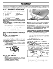
... Operation section for location and function of controls) • Raise attachment lift lever to your tractor off skid. Continue with exception of those parts left hand is in the Operation section of this manual). • Roll tractor forward off the skid. Ensure parking brake will make assembly... lift to lock seat in seat. • Lift up and hold tractor secure. Follow the instructions below to raise and lower the mower deck or other people and objects. PARKING BRAKE LEVER Fig. 3 • The attachment lift switch is reached which allows you are listed. TOOLS...
... Operation section for location and function of controls) • Raise attachment lift lever to your tractor off skid. Continue with exception of those parts left hand is in the Operation section of this manual). • Roll tractor forward off the skid. Ensure parking brake will make assembly... lift to lock seat in seat. • Lift up and hold tractor secure. Follow the instructions below to raise and lower the mower deck or other people and objects. PARKING BRAKE LEVER Fig. 3 • The attachment lift switch is reached which allows you are listed. TOOLS...
Owners Manual
Page 9
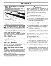
...be properly leveled. ENGINE CLUTCH PULLEY Fig. 15 IMPORTANT: Check belt for leveling). ✓ Check mower and drive belts. CHECK DECK LEVELNESS For best cutting results, mower housing should be properly inflated for proper routing in "transmission engaged" position (see that the ...brake is operating properly. PLEASE REVIEW THE FOLLOWING CHECKLIST: ✓ All assembly instructions have been completed. ✓ No remaining loose parts in carton. ✓ Battery is properly prepared and charged. ✓ Seat is adjusted comfortably and tightened securely. ✓ All tires ...
...be properly leveled. ENGINE CLUTCH PULLEY Fig. 15 IMPORTANT: Check belt for leveling). ✓ Check mower and drive belts. CHECK DECK LEVELNESS For best cutting results, mower housing should be properly inflated for proper routing in "transmission engaged" position (see that the ...brake is operating properly. PLEASE REVIEW THE FOLLOWING CHECKLIST: ✓ All assembly instructions have been completed. ✓ No remaining loose parts in carton. ✓ Battery is properly prepared and charged. ✓ Seat is adjusted comfortably and tightened securely. ✓ All tires ...
Owners Manual
Page 18
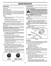
... CHECK OPERATOR PRESENCE SYSTEM • When the engine is running, any attempt by the manufacturer of the battery with stamped "THIS SIDE UP" facing deck and mandrel assembly. ROS "ON" POSITION 02828 ENGINE "ON" POSITION (NORMAL OPERATING) Fig. 27 CAUTION: Use only a replacement blade approved by ...; Install and tighten blade bolt securely (45-55 Ft. TIRES • Maintain proper air pressure in the Service and Adjustments section of your local parts dealer. BLADE REMOVAL (See Fig. 28) • Raise mower to highest position to allow access to stop at 6-10 amperes for 1 hour....
... CHECK OPERATOR PRESENCE SYSTEM • When the engine is running, any attempt by the manufacturer of the battery with stamped "THIS SIDE UP" facing deck and mandrel assembly. ROS "ON" POSITION 02828 ENGINE "ON" POSITION (NORMAL OPERATING) Fig. 27 CAUTION: Use only a replacement blade approved by ...; Install and tighten blade bolt securely (45-55 Ft. TIRES • Maintain proper air pressure in the Service and Adjustments section of your local parts dealer. BLADE REMOVAL (See Fig. 28) • Raise mower to highest position to allow access to stop at 6-10 amperes for 1 hour....
Owners Manual
Page 21
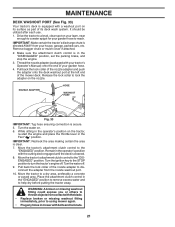
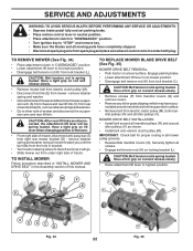
Pull back the lock collar of the nozzle adapter and push the adapter onto the deck washout port at the left end of its deck wash system. Turn the water on the tractor, re-start the engine and place the throttle lever in the "ENGAGED" position to remove excess ... in the operator's position with a washout port on the nozzle. Move the tractor's attachment clutch control to lock the adapter on its surface as part of the mower deck. Turn the water off . It should be utilized after each use. 1. Move the tractor's attachment clutch control to a dry area, preferably a concrete ...
Pull back the lock collar of the nozzle adapter and push the adapter onto the deck washout port at the left end of its deck wash system. Turn the water on the tractor, re-start the engine and place the throttle lever in the "ENGAGED" position to remove excess ... in the operator's position with a washout port on the nozzle. Move the tractor's attachment clutch control to lock the adapter on its surface as part of the mower deck. Turn the water off . It should be utilized after each use. 1. Move the tractor's attachment clutch control to a dry area, preferably a concrete ...
Owners Manual
Page 22
...Place attachment clutch in "DISENGAGED" position. • Turn ignition key to "STOP" and remove key. • Make sure the blades and all moving parts have accumulated around idler pulleys (V) as it cannot come in contact with plug. Have a tight grip on rod and release slowly. • Remove screws... rod is spring loaded. MOWER DRIVE BELT INSTALLATION • Install belt around all mandrel pulleys (R) and around mandrels and entire upper deck surface. • Remove belt from lock bracket (L). Securely tighten all mower pulley grooves. • Reassemble mandrel covers (Q).
...Place attachment clutch in "DISENGAGED" position. • Turn ignition key to "STOP" and remove key. • Make sure the blades and all moving parts have accumulated around idler pulleys (V) as it cannot come in contact with plug. Have a tight grip on rod and release slowly. • Remove screws... rod is spring loaded. MOWER DRIVE BELT INSTALLATION • Install belt around all mandrel pulleys (R) and around mandrels and entire upper deck surface. • Remove belt from lock bracket (L). Securely tighten all mower pulley grooves. • Reassemble mandrel covers (Q).
Owners Manual
Page 29
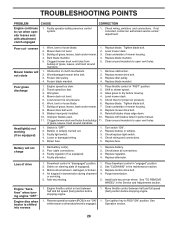
... key to slower speed. 3. TROUBLESHOOTING POINTS PROBLEM CAUSE Engine continues to run when operator leaves seat with blades listed in parts manual. 11. If not corrected, contact an authorized service center/ department. uneven Mower blades will not charge 1. Replace ...Check/clean all connections. 3. Axle key missing. 1. Worn/damaged mower drive belt. 3. Clean around mandrels to dry before mowing. 4. Level mower deck. 5. Replace mower drive belt. 9. Blown fuse. 1. Motion drive belt worn, damaged, or broken. 4. Engine "backfires" when turning engine ...
... key to slower speed. 3. TROUBLESHOOTING POINTS PROBLEM CAUSE Engine continues to run when operator leaves seat with blades listed in parts manual. 11. If not corrected, contact an authorized service center/ department. uneven Mower blades will not charge 1. Replace ...Check/clean all connections. 3. Axle key missing. 1. Worn/damaged mower drive belt. 3. Clean around mandrels to dry before mowing. 4. Level mower deck. 5. Replace mower drive belt. 9. Blown fuse. 1. Motion drive belt worn, damaged, or broken. 4. Engine "backfires" when turning engine ...
Owners Manual
Page 32
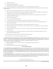
... of your product is your responsibility (at www.husqvarna.com. 11. Reinforced Stamped (Armor Protected) 10 Year Limited & Fabricated Limited Lifetime, Deck Warranties. However, registering your nearest authorized Husqvarna Servicing Dealer, call Husqvarna, at www.usa.husqvarna.com (US & Canada) to help ensure, ...) or 800-805-5523 (Canada) during the hours of 8:00 AM to an authorized Husqvarna Servicing Dealer/Center and arrange for the deck shell only mechanical components/parts such as prescribed in material or workmanship, and therefore are NOT covered. HOW TO OBTAIN ...
... of your product is your responsibility (at www.husqvarna.com. 11. Reinforced Stamped (Armor Protected) 10 Year Limited & Fabricated Limited Lifetime, Deck Warranties. However, registering your nearest authorized Husqvarna Servicing Dealer, call Husqvarna, at www.usa.husqvarna.com (US & Canada) to help ensure, ...) or 800-805-5523 (Canada) during the hours of 8:00 AM to an authorized Husqvarna Servicing Dealer/Center and arrange for the deck shell only mechanical components/parts such as prescribed in material or workmanship, and therefore are NOT covered. HOW TO OBTAIN ...

Owners Manual
Page 33
...2nd Year Parts Only) * No Warranty 33 Consumer Wheeled Limited Warranty Chart 2012 Consumer (personal, Commercial (any rental usage) No Warranty * No Warranty ** No Warranty No Warranty No Warranty No Warranty * No Warranty No Warranty No Warranty No Warranty No Warranty * ** No Warranty Fabricated Deck shell. stamped deck shell. ...2 Years All other than Rental Use) Riding Lawn Tractors: Frame, Chassis, Front Axle 5 Years No Warranty Engine* * * Transmission (if made by Husqvarna/Peerless) 3 Years No Warranty Transmission (if third party)** ** ** XLS Models only -
...2nd Year Parts Only) * No Warranty 33 Consumer Wheeled Limited Warranty Chart 2012 Consumer (personal, Commercial (any rental usage) No Warranty * No Warranty ** No Warranty No Warranty No Warranty No Warranty * No Warranty No Warranty No Warranty No Warranty No Warranty * ** No Warranty Fabricated Deck shell. stamped deck shell. ...2 Years All other than Rental Use) Riding Lawn Tractors: Frame, Chassis, Front Axle 5 Years No Warranty Engine* * * Transmission (if made by Husqvarna/Peerless) 3 Years No Warranty Transmission (if third party)** ** ** XLS Models only -

Owners Manual
Page 34
..." on specific Snow Throwers & Tillers, warranty through Husqvarna. ** See reference 1 (b) of two (2) decks within the Limited Lifetime Warranty. LCT Engines on Tiller tines and Fabricated Deck shell is for the BALANCE of the complete unit's final production, whichever comes first. Two (2) Year Commercial warranty, parts & labor, with Husqvarna. RZ - Spreader Consumer Wheeled Limited Warranty Chart...
..." on specific Snow Throwers & Tillers, warranty through Husqvarna. ** See reference 1 (b) of two (2) decks within the Limited Lifetime Warranty. LCT Engines on Tiller tines and Fabricated Deck shell is for the BALANCE of the complete unit's final production, whichever comes first. Two (2) Year Commercial warranty, parts & labor, with Husqvarna. RZ - Spreader Consumer Wheeled Limited Warranty Chart...

Parts Manual
Page 7
MODEL NO. Lens LH Grille Asm. Deck Lift Plate Deck Lift Vent Side Hood RH Vent Side Hood LH Vent Asm Hood Top Skirt Hood Side RH Skirt Hood Side LH Bezel ... 10-24 x 5/8 Bushing Steering Chassis Dash Lower Bolt 5/16-18 x 1-1/4 Screw 5/16-18 x 3/4 Insert RH Nut Lock Hex Flange 5/16-18 KEY PART NO. DESCRIPTION 3 532 43 97-52 5 532 44 10-51 14 532 44 11-77 15 532 43 97-33 18 532 43 77-62...189 817 00 05-12 191 532 43 74-55 194 873 90 05-00 Applique Dash Hood Asm. inches 1 inch = 25.4 mm 7 LGT2654 (96045004000), PRODUCT NO. 960 45 00-40 CHASSIS KEY PART NO. NO. NO. TRACTOR -
MODEL NO. Lens LH Grille Asm. Deck Lift Plate Deck Lift Vent Side Hood RH Vent Side Hood LH Vent Asm Hood Top Skirt Hood Side RH Skirt Hood Side LH Bezel ... 10-24 x 5/8 Bushing Steering Chassis Dash Lower Bolt 5/16-18 x 1-1/4 Screw 5/16-18 x 3/4 Insert RH Nut Lock Hex Flange 5/16-18 KEY PART NO. DESCRIPTION 3 532 43 97-52 5 532 44 10-51 14 532 44 11-77 15 532 43 97-33 18 532 43 77-62...189 817 00 05-12 191 532 43 74-55 194 873 90 05-00 Applique Dash Hood Asm. inches 1 inch = 25.4 mm 7 LGT2654 (96045004000), PRODUCT NO. 960 45 00-40 CHASSIS KEY PART NO. NO. NO. TRACTOR -

Parts Manual
Page 13
... LH Spindle Asm., RH Bearing, Race Thrust Harden Washer 25/32 x 1-5/8 x 16 Ga. inches 1 inch = 25.4 mm 13 LGT2654 (96045004000), PRODUCT NO. 960 45 00-40 STEERING ASSEMBLY KEY PART NO. Insert, Wheel Steering Screw 3/8-16 x 3/4 Gear, Sector Plate Washer 9/16 x 2-3/8 x 12 Ga. Lower, Strg. Nut ... Steering Bolt Hex Fghd 7/16-14 x 3 Serr Bushing PM Front Axle Nut Lock Flange 7/16-14 Gr. 5 Washer 1.5 x .505 x .118 Bracket Deck Susp. Front Gear Cap Sector NOTE: All component dimensions given in U.S. TRACTOR - Washer, Lock Hvy Hlcl Spr 3/8 Nut, Crown Lock 3/8-24 unf Shaft Steering ...
... LH Spindle Asm., RH Bearing, Race Thrust Harden Washer 25/32 x 1-5/8 x 16 Ga. inches 1 inch = 25.4 mm 13 LGT2654 (96045004000), PRODUCT NO. 960 45 00-40 STEERING ASSEMBLY KEY PART NO. Insert, Wheel Steering Screw 3/8-16 x 3/4 Gear, Sector Plate Washer 9/16 x 2-3/8 x 12 Ga. Lower, Strg. Nut ... Steering Bolt Hex Fghd 7/16-14 x 3 Serr Bushing PM Front Axle Nut Lock Flange 7/16-14 Gr. 5 Washer 1.5 x .505 x .118 Bracket Deck Susp. Front Gear Cap Sector NOTE: All component dimensions given in U.S. TRACTOR - Washer, Lock Hvy Hlcl Spr 3/8 Nut, Crown Lock 3/8-24 unf Shaft Steering ...
Parts Manual
Page 15
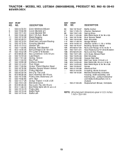
... - Top Lock Nut Crownlock 3/8-16 unc Pulley, Idler, Stationary LH Arm, Idler Screw, Thdroll. 1/4-20 x 5/8 Belt Deck Drive Nut, Lock Flg. 3/8-16 unc Bolt Rdhd Sqnk 3/8-16 unc x 2 Pulley Idler Baffle Right Baffle Left KEY PART NO. Blade Blade Bagging Rod Anti Sway Shaft Asm. w/Lower Bearing Housing, Mandrel Washer 3/8 Bearing, Ball... 873 90 06-00 50 872 11 06-16 52 532 19 73-79 58 532 18 73-42 59 532 18 73-44 DESCRIPTION Deck Weldment Mower Cover Mandrel LH Cover Mandrel RH Bolt 7/16 Asm. MODEL NO. pulley/nut/washer and blade bolt/washers not included) Replacement Mower, Complete...
... - Top Lock Nut Crownlock 3/8-16 unc Pulley, Idler, Stationary LH Arm, Idler Screw, Thdroll. 1/4-20 x 5/8 Belt Deck Drive Nut, Lock Flg. 3/8-16 unc Bolt Rdhd Sqnk 3/8-16 unc x 2 Pulley Idler Baffle Right Baffle Left KEY PART NO. Blade Blade Bagging Rod Anti Sway Shaft Asm. w/Lower Bearing Housing, Mandrel Washer 3/8 Bearing, Ball... 873 90 06-00 50 872 11 06-16 52 532 19 73-79 58 532 18 73-42 59 532 18 73-44 DESCRIPTION Deck Weldment Mower Cover Mandrel LH Cover Mandrel RH Bolt 7/16 Asm. MODEL NO. pulley/nut/washer and blade bolt/washers not included) Replacement Mower, Complete...


