
Owner Manual
Page 2
... special requirements for repairs. When this product. Use only original parts for any of California to the unit without prior notification. Do not modify or install non-standard equipment to cause cancer and birth defects or other parts voids the warranty. Modifications to operate the mower. Service agent contact information: This operator's manual is an odorless, colorless, poisonous gas. WARNING: Failure to...
... special requirements for repairs. When this product. Use only original parts for any of California to the unit without prior notification. Do not modify or install non-standard equipment to cause cancer and birth defects or other parts voids the warranty. Modifications to operate the mower. Service agent contact information: This operator's manual is an odorless, colorless, poisonous gas. WARNING: Failure to...
Owner Manual
Page 3
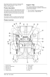
... tasks. Control levers 2. Fuel tank cap 5. Throttle control 1 6. Do not use The product is a stand on open and level ground only. Fuel gauge 8. Hour meter 9. An hour meter shows how many hours the product has been used. Stationary bar 4. Choke control 7. Hydraulic release lever 3. The product numbers are found on page 3 for the location of the product. The control levers let the operator steer the product and adjust the speed of the type plate...
... tasks. Control levers 2. Fuel tank cap 5. Throttle control 1 6. Do not use The product is a stand on open and level ground only. Fuel gauge 8. Hour meter 9. An hour meter shows how many hours the product has been used. Stationary bar 4. Choke control 7. Hydraulic release lever 3. The product numbers are found on page 3 for the location of the product. The control levers let the operator steer the product and adjust the speed of the type plate...

Owner Manual
Page 4
... blades if the blades are engaged or the parking brake is controlled by the 2 control levers. A B Steering controls The direction of the blades. The ignition key has 4 positions: • Stop position (A) • Idle speed (A) - Transport latch 13. Deck lifting lever 16. Adjustable bar Stand on page 8. Refer to Operation conditions on or walk behind lawn mower. The engine and the drive to To set the product in a folded position. decreases the engine speed. • Full throttle (B) - Choke control The choke control is used...
... blades if the blades are engaged or the parking brake is controlled by the 2 control levers. A B Steering controls The direction of the blades. The ignition key has 4 positions: • Stop position (A) • Idle speed (A) - Transport latch 13. Deck lifting lever 16. Adjustable bar Stand on page 8. Refer to Operation conditions on or walk behind lawn mower. The engine and the drive to To set the product in a folded position. decreases the engine speed. • Full throttle (B) - Choke control The choke control is used...
Owner Manual
Page 5
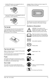
... drive to the blades or other equipment. Read the operator's manual carefully and make sure that you understand the instructions before you use approved hearing protection. Fuel shut-off valve is perpendicular to the fuel line. The fuel shut-off valve Refer to Product overview on page 3 for identification of the hour meter. • Push the PTO button in the fuse box, behind the engine cover...
... drive to the blades or other equipment. Read the operator's manual carefully and make sure that you understand the instructions before you use approved hearing protection. Fuel shut-off valve is perpendicular to the fuel line. The fuel shut-off valve Refer to Product overview on page 3 for identification of the hour meter. • Push the PTO button in the fuse box, behind the engine cover...
Owner Manual
Page 7
... recommended direction on level ground, disengage the attachment, set parking brake, and stop engine/ motor. • Do not mow in reverse unless absolutely necessary. If you last saw them. • Keep children out of a responsible adult other than the operator. • Do not carry children, even with the blade(s) shut off and be seriously injured or interfere with a grass catcher or other attachment(s). Never assume...
... recommended direction on level ground, disengage the attachment, set parking brake, and stop engine/ motor. • Do not mow in reverse unless absolutely necessary. If you last saw them. • Keep children out of a responsible adult other than the operator. • Do not carry children, even with the blade(s) shut off and be seriously injured or interfere with a grass catcher or other attachment(s). Never assume...
Owner Manual
Page 8
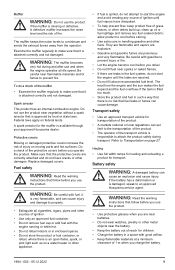
... you use the seat belt when operating the product. • Lower a folding ROPS temporarily only when absolutely necessary. Do not use the product if protective plates, protective covers, safety switches or other items that can result in these situations: • The parking brake is pushed down. Operation conditions These conditions are necessary to start the engine: • The control levers are recommended. The drive of the blades is disengaged...
... you use the seat belt when operating the product. • Lower a folding ROPS temporarily only when absolutely necessary. Do not use the product if protective plates, protective covers, safety switches or other items that can result in these situations: • The parking brake is pushed down. Operation conditions These conditions are necessary to start the engine: • The control levers are recommended. The drive of the blades is disengaged...
Owner Manual
Page 9
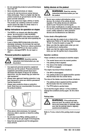
... Husqvarna dealer. Spark arrestor This product has an internal-combustion engine. It is very flammable, and can cause an explosion and cause injury. WARNING: The muffler becomes very hot during transport. Do a check of ignition. • Use only an approved fuel container. • Do not remove fuel cap or add fuel with good airflow. • Keep flammable materials at idle speed. Replace damaged covers...
... Husqvarna dealer. Spark arrestor This product has an internal-combustion engine. It is very flammable, and can cause an explosion and cause injury. WARNING: The muffler becomes very hot during transport. Do a check of ignition. • Use only an approved fuel container. • Do not remove fuel cap or add fuel with good airflow. • Keep flammable materials at idle speed. Replace damaged covers...
Owner Manual
Page 10
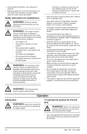
... cause serious injury. Keep the battery away from the battery. If a leak occurs, have sufficient force to Technical data on a level surface. • The parking brake is applied. • The ignition key in good condition. • Do not change the adjustment of governors. Use caution when servicing blades. For best performance and safety, do maintenance on the engine or the cutting deck without these conditions: • The...
... cause serious injury. Keep the battery away from the battery. If a leak occurs, have sufficient force to Technical data on a level surface. • The parking brake is applied. • The ignition key in good condition. • Do not change the adjustment of governors. Use caution when servicing blades. For best performance and safety, do maintenance on the engine or the cutting deck without these conditions: • The...

Owner Manual
Page 12
... disengage the drive on page 12. 2. To engage and disengage the parking brake • Pull the parking brake lever rearward to ½ throttle position. 3. To set the cutting deck in transport position during transportation. • Pull back the deck lifting lever (A) fully. To start the engine 1. Push the PTO button to To disengage and engage the drive system on page 3 for the correct cutting height. 4. Refer to disengage the drive system. To disengage and engage the drive system CAUTION: Only disengage the drive...
... disengage the drive on page 12. 2. To engage and disengage the parking brake • Pull the parking brake lever rearward to ½ throttle position. 3. To set the cutting deck in transport position during transportation. • Pull back the deck lifting lever (A) fully. To start the engine 1. Push the PTO button to To disengage and engage the drive system on page 3 for the correct cutting height. 4. Refer to disengage the drive system. To disengage and engage the drive system CAUTION: Only disengage the drive...

Owner Manual
Page 13
... 2 control levers are pushed forward. Do the steps that follow to turn the ignition key to make the product turn . 13 Refer to the full throttle position. Push the throttle control to To engage and disengage the parking brake on page 12. 2. Put the 2 control levers in the choke control if the choke was used. 8. If the engine does not start position for 3-5 minutes before you go in and turn left . 3. b) Pull the right control lever rearward...
... 2 control levers are pushed forward. Do the steps that follow to turn the ignition key to make the product turn . 13 Refer to the full throttle position. Push the throttle control to To engage and disengage the parking brake on page 12. 2. Put the 2 control levers in the choke control if the choke was used. 8. If the engine does not start position for 3-5 minutes before you go in and turn left . 3. b) Pull the right control lever rearward...

Owner Manual
Page 14
... throttle position. 6. Remove the ignition key from the ignition when you are away from the 2 control levers to To set the cutting deck in transport position or mow position on a stopped wheel. 1. To adjust the tracking speed 1. Pull out the retaining clip from the vertical control rod. 2. Adjust the coupler until the speed is necessary to adjust the cutting height during operation, refer to disengage the OPC. 5. Wet grass can give a bad cutting result. • Start with a high cutting height...
... throttle position. 6. Remove the ignition key from the ignition when you are away from the 2 control levers to To set the cutting deck in transport position or mow position on a stopped wheel. 1. To adjust the tracking speed 1. Pull out the retaining clip from the vertical control rod. 2. Adjust the coupler until the speed is necessary to adjust the cutting height during operation, refer to disengage the OPC. 5. Wet grass can give a bad cutting result. • Start with a high cutting height...
Owner Manual
Page 15
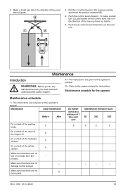
... the safety chapter. B C A 3. O = Refer to the engine manual for the operator Maintenance schedule * = The instructions are not given in this operator's manual. O Do a check of the engine oil. Maintenance schedule for instructions. X Do a check of the level of the hydraulic oil level. Make sure that there are given in this operator's manual. Push the control levers forward. X = The instructions are no damage on the control lever that is in the direction of the parking brake. Make a small turn (C), pull...
... the safety chapter. B C A 3. O = Refer to the engine manual for the operator Maintenance schedule * = The instructions are not given in this operator's manual. O Do a check of the engine oil. Maintenance schedule for instructions. X Do a check of the level of the hydraulic oil level. Make sure that there are given in this operator's manual. Push the control levers forward. X = The instructions are no damage on the control lever that is in the direction of the parking brake. Make a small turn (C), pull...

Owner Manual
Page 16
... a check of the tire pressures. Sharpen the blades.5 Replace the blades. Replace the spark plugs. Do a check of the battery connections. Do a check of the belts and the belt pulleys. X Clean around the engine. * Clean around the belts and the belt pulleys. * Do a check of the throttle cable and choke cable. Clean the foam pre-filter.3 Clean the paper filter cartridge.4 Examine the muffler and spark arrestor screen. Start the engine and blades and listen for damages on the cutting deck. Do maintenance...
... a check of the tire pressures. Sharpen the blades.5 Replace the blades. Replace the spark plugs. Do a check of the battery connections. Do a check of the belts and the belt pulleys. X Clean around the engine. * Clean around the belts and the belt pulleys. * Do a check of the throttle cable and choke cable. Clean the foam pre-filter.3 Clean the paper filter cartridge.4 Examine the muffler and spark arrestor screen. Start the engine and blades and listen for damages on the cutting deck. Do maintenance...

Owner Manual
Page 17
... covers To remove and install the engine cover The engine cover has a soft operator cushion that the engine becomes too hot. Disassemble and examine the starter.8 Do the 500-hour servicing.9 Do maintenance at electrical components or bearings. pressure washer or a steam cleaner. Detergent usually increases the damage. • Use compressed air to clean the top side of the battery to clean the product. Grass cuttings around the transmission, the transmission air...
... covers To remove and install the engine cover The engine cover has a soft operator cushion that the engine becomes too hot. Disassemble and examine the starter.8 Do the 500-hour servicing.9 Do maintenance at electrical components or bearings. pressure washer or a steam cleaner. Detergent usually increases the damage. • Use compressed air to clean the top side of the battery to clean the product. Grass cuttings around the transmission, the transmission air...

Owner Manual
Page 18
... the engine cover to get access to or near the negative terminal of the fully charged CAUTION: Do not use jumper cables to move with negative ground. To do a check of explosive gas that is too weak to start must also have a 12 V system with the parking brake engaged, let an approved service agent adjust the parking brake. 4. Pull the handle to how you start the engine. Disengage the parking brake. To remove...
... the engine cover to get access to or near the negative terminal of the fully charged CAUTION: Do not use jumper cables to move with negative ground. To do a check of explosive gas that is too weak to start must also have a 12 V system with the parking brake engaged, let an approved service agent adjust the parking brake. 4. Pull the handle to how you start the engine. Disengage the parking brake. To remove...

Owner Manual
Page 19
..., the bolt, the axle and the antiscalp roller. 3. Use 2 wrenches to disconnect the red battery cable from the ground. To remove and install the front wheels 1. Install the anti-scalp roller in the opposite sequence. The anti-scalp rollers must be set the cutting deck in the opposite sequence. Make sure that the tire pressure is correctly installed. Turn the blades to align with the cutting deck side...
..., the bolt, the axle and the antiscalp roller. 3. Use 2 wrenches to disconnect the red battery cable from the ground. To remove and install the front wheels 1. Install the anti-scalp roller in the opposite sequence. The anti-scalp rollers must be set the cutting deck in the opposite sequence. Make sure that the tire pressure is correctly installed. Turn the blades to align with the cutting deck side...

Owner Manual
Page 21
... install the deck drive belt 1. To remove the deck belt Park the product on level ground and engage the parking brake before you do this procedure. c) Tighten the jam nut. b) Tighten the neutral bolt to sharpen them. Let an approved service agent help you sharpen and balance blunt blades. • Look at a time. Assemble the new blade with the side without stamps in the front of the frame to start. Attach the blade bolt. Remove...
... install the deck drive belt 1. To remove the deck belt Park the product on level ground and engage the parking brake before you do this procedure. c) Tighten the jam nut. b) Tighten the neutral bolt to sharpen them. Let an approved service agent help you sharpen and balance blunt blades. • Look at a time. Assemble the new blade with the side without stamps in the front of the frame to start. Attach the blade bolt. Remove...

Owner Manual
Page 22
... the engine. 3. Make sure that the belt routing align with the belt routing shown on the idler arm. 9. Disconnect the clutch wire. 4. Put a 3/8 in . Remove the deck belt from the dipstick. 5. Put a 3/8 in . Put the dipstick in . / 6.4-19.0 mm of the pump belt. Install the deck drive belt. Carefully put the deck belt around the right pump pulley. 4. Pull open the operator cushion to get access to To install the deck drive belt on the 2 spindle housings. 3. Install the 2 belt covers...
... the engine. 3. Make sure that the belt routing align with the belt routing shown on the idler arm. 9. Disconnect the clutch wire. 4. Put a 3/8 in . Remove the deck belt from the dipstick. 5. Put a 3/8 in . Put the dipstick in . / 6.4-19.0 mm of the pump belt. Install the deck drive belt. Carefully put the deck belt around the right pump pulley. 4. Pull open the operator cushion to get access to To install the deck drive belt on the 2 spindle housings. 3. Install the 2 belt covers...
Owner Manual
Page 25
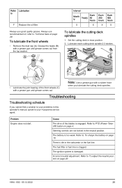
... the blades is engaged. There is too weak. To lubricate the front wheels • Remove the dust cap (A). Troubleshooting Troubleshooting schedule If you lubricate the cutting deck spindles. The battery is dirt in this operator's manual, speak to To charge the battery on page 18. Set the cutting deck in the neutral position. The ignition system is clogged. Always use good quality grease. Steering controls are not locked in mow position. 2. Refer to PTO (Power TakeOff...
... the blades is engaged. There is too weak. To lubricate the front wheels • Remove the dust cap (A). Troubleshooting Troubleshooting schedule If you lubricate the cutting deck spindles. The battery is dirt in this operator's manual, speak to To charge the battery on page 18. Set the cutting deck in the neutral position. The ignition system is clogged. Always use good quality grease. Steering controls are not locked in mow position. 2. Refer to PTO (Power TakeOff...
Owner Manual
Page 26
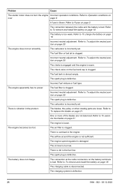
... the fuel tank cap is clogged. The fuel filter or fuel jet is clogged. Incorrect neutral adjustment. The check valve on page 20. The spark plug is disconnected. Refer to To remove and install the battery on page 20. Refer to To adjust the neutral position on page 18. The engine becomes too hot. The charging cable is defective. Problem Cause The starter motor does not turn the engine Incorrect operation conditions. The battery is...
... the fuel tank cap is clogged. The fuel filter or fuel jet is clogged. Incorrect neutral adjustment. The check valve on page 20. The spark plug is disconnected. Refer to To remove and install the battery on page 20. Refer to To adjust the neutral position on page 18. The engine becomes too hot. The charging cable is defective. Problem Cause The starter motor does not turn the engine Incorrect operation conditions. The battery is...


