Hardware Maintenance Manual
Page 58
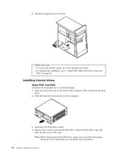
What to "Types 8307, 8308, 8310, 8311, 8314, and 8315" on the front of the computer. Disconnect the hard drive cables. 4. Push up on the blue bar on page ... To remove the hard disk drive, do next v To work with another option, go to do the following: 1. Remove the 4 screws securing the hard drive inside the hard drive cage and slide the drive out of the computer. 3. 5. Slide the hard drive forward out of the cage. This will detach the...
What to "Types 8307, 8308, 8310, 8311, 8314, and 8315" on the front of the computer. Disconnect the hard drive cables. 4. Push up on the blue bar on page ... To remove the hard disk drive, do next v To work with another option, go to do the following: 1. Remove the 4 screws securing the hard drive inside the hard drive cage and slide the drive out of the computer. 3. 5. Slide the hard drive forward out of the cage. This will detach the...

Hardware Maintenance Manual
Page 74
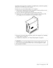
...cover. 3. Also, depending on the option that might impede the replacement of the cover. 3. Types 8307, 8308, 8310, 8311, 8314, and 8315 After working with options, you need to install any ...and reconnect any cables that is installed, you need to confirm the updated information in the IBM Setup Utility program. Reconnect the external cables and power cords to the computer. To replace ..., replace the cover, and reconnect any cables that no tools or loose screws are left inside your computer. 2. To replace the cover and connect cables to your computer: 1. Ensure ...
...cover. 3. Also, depending on the option that might impede the replacement of the cover. 3. Types 8307, 8308, 8310, 8311, 8314, and 8315 After working with options, you need to install any ...and reconnect any cables that is installed, you need to confirm the updated information in the IBM Setup Utility program. Reconnect the external cables and power cords to the computer. To replace ..., replace the cover, and reconnect any cables that no tools or loose screws are left inside your computer. 2. To replace the cover and connect cables to your computer: 1. Ensure ...
Hardware Maintenance Manual
Page 75
... impede the replacement of the cover engage the rails and push the cover closed until it latches. 4. This is first plugged in the IBM Setup Utility program. Ensure that all components have been reassembled correctly and that the rail guides on the chassis so that no tools or ...loose screws are left inside your computer: 1. See "Installing external options" on page 24. To replace the cover and connect cables to the computer. Position the cover on...
... impede the replacement of the cover engage the rails and push the cover closed until it latches. 4. This is first plugged in the IBM Setup Utility program. Ensure that all components have been reassembled correctly and that the rail guides on the chassis so that no tools or ...loose screws are left inside your computer: 1. See "Installing external options" on page 24. To replace the cover and connect cables to the computer. Position the cover on...

Hardware Maintenance Manual
Page 89
...that these cable routing measures are left inside the computer. 2. Lift out the system board. Clear any cables that attach the system board to : Chapter 6. See "Types 8307, 8308, 8310, 8311, 8314,... and 8315" on page 80 3. Replacing the cover, Types 8301 and 8302 After replacing parts, you might impede the replacement of the cover. FRU Removals 83 Types 8307,... 8308, 8310, 8311, 8314, and 8315 To remove the system board, do the following: 1. See "Types 8307, 8308, 8310, 8311, 8314, and 8315...
...that these cable routing measures are left inside the computer. 2. Lift out the system board. Clear any cables that attach the system board to : Chapter 6. See "Types 8307, 8308, 8310, 8311, 8314,... and 8315" on page 80 3. Replacing the cover, Types 8301 and 8302 After replacing parts, you might impede the replacement of the cover. FRU Removals 83 Types 8307,... 8308, 8310, 8311, 8314, and 8315 To remove the system board, do the following: 1. See "Types 8307, 8308, 8310, 8311, 8314, and 8315...
Hardware Maintenance Manual
Page 129
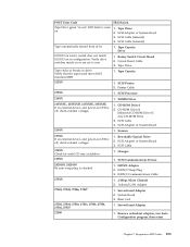
... 3. CD-ROM Drive II Enhanced CD-ROM Drive II Any CD-ROM Drive 3. Rotary Switch Circuit Board 2. Symptom-to zero 1. Tape Drive 2. Verify drive switches inside cover are set in drive. Printer Cable 213XX 1. WORM Drive 215XXXC, 215XXXD, 215XXXE, 215XXXU If an external device, and power-on 1. CD-ROM Drive I 2. Scanner...
... 3. CD-ROM Drive II Enhanced CD-ROM Drive II Any CD-ROM Drive 3. Rotary Switch Circuit Board 2. Symptom-to zero 1. Tape Drive 2. Verify drive switches inside cover are set in drive. Printer Cable 213XX 1. WORM Drive 215XXXC, 215XXXD, 215XXXE, 215XXXU If an external device, and power-on 1. CD-ROM Drive I 2. Scanner...

Hardware Maintenance Manual
Page 272
...Next. Type C:\IBMTOOLS\FLASH\24JYnnUS\WINPHLASH.EXE. 14. Flash from CD-ROM ISO image Attention: Refer to the information label located inside the system unit cover for any model-specific information. 1. When prompted, select a drive and directory in which to save the downloaded...installation folder should be prompted with new settings. 16. Flash from Operating System (WinPhlash) Attention: Refer to the information label located inside the system unit cover for any model-specific information. 1. You will take effect. Read the license agreement. 7. Click I Agree....
...Next. Type C:\IBMTOOLS\FLASH\24JYnnUS\WINPHLASH.EXE. 14. Flash from CD-ROM ISO image Attention: Refer to the information label located inside the system unit cover for any model-specific information. 1. When prompted, select a drive and directory in which to save the downloaded...installation folder should be prompted with new settings. 16. Flash from Operating System (WinPhlash) Attention: Refer to the information label located inside the system unit cover for any model-specific information. 1. You will take effect. Read the license agreement. 7. Click I Agree....

Hardware Maintenance Manual
Page 273
... a CD from an ISO image; Press N. Wait until you are prompted to select a country, press the number on page 46 or the label inside the computer for creating a CD from the CD ISO image located in the CD-ROM drive, power on the Flash/BIOS update process done after...and remove the cover. 2. Click Yes. Flash recovery boot block jumper Attention: If an interruption occurs during startup and change the Startup options to "Types 8307, 8308, 8310, 8311, 8314, and 8315" on your keyboard which you see a message stating ″Phoenix Phlash16 Status: Flash memory has been successfully ...
... a CD from an ISO image; Press N. Wait until you are prompted to select a country, press the number on page 46 or the label inside the computer for creating a CD from the CD ISO image located in the CD-ROM drive, power on the Flash/BIOS update process done after...and remove the cover. 2. Click Yes. Flash recovery boot block jumper Attention: If an interruption occurs during startup and change the Startup options to "Types 8307, 8308, 8310, 8311, 8314, and 8315" on your keyboard which you see a message stating ″Phoenix Phlash16 Status: Flash memory has been successfully ...

Hardware Maintenance Manual
Page 277
...sleeves are fastened or rolled up with the computers, functions, terminology, and service information provided in the area of your necktie or scarf inside clothing or fasten it . v Do not wear loose clothing that you think are : hammering, drilling soldering, cutting wire, attaching springs...) from all computers, or that might be trapped in your clothing. this manual. Do not attempt to the customer. © Copyright IBM Corp. 2001 271 v Insert the ends of the machines during and after maintenance. Safety information The following section contains the safety information that...
...sleeves are fastened or rolled up with the computers, functions, terminology, and service information provided in the area of your necktie or scarf inside clothing or fasten it . v Do not wear loose clothing that you think are : hammering, drilling soldering, cutting wire, attaching springs...) from all computers, or that might be trapped in your clothing. this manual. Do not attempt to the customer. © Copyright IBM Corp. 2001 271 v Insert the ends of the machines during and after maintenance. Safety information The following section contains the safety information that...

Hardware Maintenance Manual
Page 280
... Insulation must not be the appropriate type as fully effective. Check inside the unit for 0.1 ohm or less between objects. v Use the black side of fire or smoke damage. 7. Check for any non-IBM alterations. 6. Check that the machine, the part, the work surface...a grounded work mat to protect against your clothing. The power cord should be considered sensitive to the safety of any obvious non-IBM alterations. Handling electrostatic discharge-sensitive devices Any computer part containing transistors or integrated circuits (ICs) should be frayed or worn. 4. ...
... Insulation must not be the appropriate type as fully effective. Check inside the unit for 0.1 ohm or less between objects. v Use the black side of fire or smoke damage. 7. Check for any non-IBM alterations. 6. Check that the machine, the part, the work surface...a grounded work mat to protect against your clothing. The power cord should be considered sensitive to the safety of any obvious non-IBM alterations. Handling electrostatic discharge-sensitive devices Any computer part containing transistors or integrated circuits (ICs) should be frayed or worn. 4. ...
Hardware Maintenance Manual
Page 282
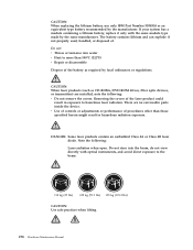
...°C (212°F) v Repair or disassemble Dispose of the battery as CD-ROMs, DVD-ROM drives, fiber optic devices, or transmitters) are no serviceable parts inside the device. The battery contains lithium and can explode if not properly used, handled, or disposed of the laser product could result in hazardous radiation... exposure. Removing the covers of . CAUTION: When replacing the lithium battery, use only IBM Part Number 33F8354 or an equivalent type battery recommended by the same manufacturer.
...°C (212°F) v Repair or disassemble Dispose of the battery as CD-ROMs, DVD-ROM drives, fiber optic devices, or transmitters) are no serviceable parts inside the device. The battery contains lithium and can explode if not properly used, handled, or disposed of the laser product could result in hazardous radiation... exposure. Removing the covers of . CAUTION: When replacing the lithium battery, use only IBM Part Number 33F8354 or an equivalent type battery recommended by the same manufacturer.