Product Manual
Page 1
HD (IR) Vandal Proof Network Dome Camera User's Manual Version 1.4.0
HD (IR) Vandal Proof Network Dome Camera User's Manual Version 1.4.0

Product Manual
Page 3
... All installation and operation here should conform to better prevent thunder. it may result in device damage! Please make sure the CCD (CMOS) component is recommended to be grounded to the device at the same time; We assume no liability or responsibility for any problems caused by unauthorized modifications or attempted repair. 5.Environment This series network camera should...
... All installation and operation here should conform to better prevent thunder. it may result in device damage! Please make sure the CCD (CMOS) component is recommended to be grounded to the device at the same time; We assume no liability or responsibility for any problems caused by unauthorized modifications or attempted repair. 5.Environment This series network camera should...
Product Manual
Page 4
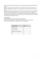
... first and then use it to use the camera. Dome enclosure is the optical component, do not touch the enclosure when you are installing the device or clean the enclosure when you do not use all the components are doing maintenance work. Before installation, please open the...of camera with IR function. 7. Finally use the blower to clean the device. Accessory Name Network Camera Quick Start Guide Installation Accessories Bag CD Amount 1 1 1 1 iii Do not touch the CCD (CMOS) optic component. You can use the dry cloth to clean the dust on the lens surface. Please use cloth)...
... first and then use it to use the camera. Dome enclosure is the optical component, do not touch the enclosure when you are installing the device or clean the enclosure when you do not use all the components are doing maintenance work. Before installation, please open the...of camera with IR function. 7. Finally use the blower to clean the device. Accessory Name Network Camera Quick Start Guide Installation Accessories Bag CD Amount 1 1 1 1 iii Do not touch the CCD (CMOS) optic component. You can use the dry cloth to clean the dust on the lens surface. Please use cloth)...

Product Manual
Page 5
Table of Contents 1 General Introduction...1 1.1 Overview ...1 1.2 Features ...1 1.3 Specifications ...2 1.3.1 Performance ...2 2 Structure ...4 2.1 Dimensions ...4 2.2 Port Description...4 2.3 Bidirectional talk ...8 2.3.1 Device-end to PC-end 9 2.3.2 PC-end to the Device-end 9 2.4 Alarm Setup ...9 3 Installation ...12 3.1 Device Installation Introduction 12 3.2 Device Installation Steps 12 3.2.1 General Installation 12 3.2.2 Manual Zoom Lens Focus Operation 16 3.2.3 Side Cable Exit 17 3.2.4 Cable Connection 17 3.3 Micro SD Card Installation 18 4 Quick Configuration Tool ...20 iv
Table of Contents 1 General Introduction...1 1.1 Overview ...1 1.2 Features ...1 1.3 Specifications ...2 1.3.1 Performance ...2 2 Structure ...4 2.1 Dimensions ...4 2.2 Port Description...4 2.3 Bidirectional talk ...8 2.3.1 Device-end to PC-end 9 2.3.2 PC-end to the Device-end 9 2.4 Alarm Setup ...9 3 Installation ...12 3.1 Device Installation Introduction 12 3.2 Device Installation Steps 12 3.2.1 General Installation 12 3.2.2 Manual Zoom Lens Focus Operation 16 3.2.3 Side Cable Exit 17 3.2.4 Cable Connection 17 3.3 Micro SD Card Installation 18 4 Quick Configuration Tool ...20 iv

Product Manual
Page 7
... Power External power adapter DC12V/AC 24V Support PoE. When it to pre-record audio file) Function Real-time video detect: motion detect, camera masking. Can generate an alarm when network abnormal, Micro SD card abnormal event occurred. Network camera supports one group. The user right shall not exceed the group right. Network Management Realize network camera configuration and management via web or client-end. It adopts audio...
... Power External power adapter DC12V/AC 24V Support PoE. When it to pre-record audio file) Function Real-time video detect: motion detect, camera masking. Can generate an alarm when network abnormal, Micro SD card abnormal event occurred. Network camera supports one group. The user right shall not exceed the group right. Network Management Realize network camera configuration and management via web or client-end. It adopts audio...

Product Manual
Page 8
... record, and remote operation at the same time. File extension name is adjustable. Support customized setup. it may result in IR light. Motorized Focus Video Compression Standard Video Frame Rate Video Bit Rate Video Flip Snapshot Support remote motorized zoom focus function. User Interface Remote operation interface such as WEB, DSS, PSS System Status Micro SD card status, bit stream statistics, log, and software version. Assistant Function Log function Support PAL/NTSC Day/Night mode auto switch...
... record, and remote operation at the same time. File extension name is adjustable. Support customized setup. it may result in IR light. Motorized Focus Video Compression Standard Video Frame Rate Video Bit Rate Video Flip Snapshot Support remote motorized zoom focus function. User Interface Remote operation interface such as WEB, DSS, PSS System Status Micro SD card status, bit stream statistics, log, and software version. Assistant Function Log function Support PAL/NTSC Day/Night mode auto switch...

Product Manual
Page 9
... (18*22) detection zones; Activation event, alarm device, audio/video storage, image snapshot, log, email function and etc. 1-channel input,1-channel output Manual>External alarm >Video detect>Schedule Local Storage Support Micro SD card storage Network Wire Network Network Protocol Remote Operation Video Output Reset 1-channel wire Ethernet port, 10/100 Base-T Ethernet HTTP,TCP,ARP,RTSP,RTP,UDP,RTCP,SMTP,FTP,DHCP,DNS,DDNS,PP POE,IPv4/v6,SNMP,QoS,UPnP,NTP. Channel title, time title, motion detect, privacy mask. [email protected] motorized zoom focus lens CS. sensitivity level...
... (18*22) detection zones; Activation event, alarm device, audio/video storage, image snapshot, log, email function and etc. 1-channel input,1-channel output Manual>External alarm >Video detect>Schedule Local Storage Support Micro SD card storage Network Wire Network Network Protocol Remote Operation Video Output Reset 1-channel wire Ethernet port, 10/100 Base-T Ethernet HTTP,TCP,ARP,RTSP,RTP,UDP,RTCP,SMTP,FTP,DHCP,DNS,DDNS,PP POE,IPv4/v6,SNMP,QoS,UPnP,NTP. Channel title, time title, motion detect, privacy mask. [email protected] motorized zoom focus lens CS. sensitivity level...

Product Manual
Page 14
... Connect to Micro SD card to restore factory default setup. Default input is to realize local storage. 11 POWER 12V power port / The power port of the external connected cable. Support PoE. It is to receive the on-off signal from the devices such as sound box. It is to receive the analog audio signal from the external alarm source. light Connect to fan to standard Ethernet port. Connect to reduce device 9 Fan port / / internal problem. Output audio signal to view video...
... Connect to Micro SD card to restore factory default setup. Default input is to realize local storage. 11 POWER 12V power port / The power port of the external connected cable. Support PoE. It is to receive the on-off signal from the devices such as sound box. It is to receive the analog audio signal from the external alarm source. light Connect to fan to standard Ethernet port. Connect to reduce device 9 Fan port / / internal problem. Output audio signal to view video...

Product Manual
Page 15
Login the Web and then click the Talk button to the audio output port of the device. Listening Operation At the device end, speak via the speaker or the pickup, and then you can see the button becomes orange after you enabled the bidirectional talk function. Please set the alarm input 01 port for the first channel of the I /O cable. 2) Connect the alarm output device to the...
Login the Web and then click the Talk button to the audio output port of the device. Listening Operation At the device end, speak via the speaker or the pickup, and then you can see the button becomes orange after you enabled the bidirectional talk function. Please set the alarm input 01 port for the first channel of the I /O cable. 2) Connect the alarm output device to the...
Product Manual
Page 18
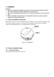
... to secure the device. You can sustain at least 3X weight of the bracket and the camera. 3.1 Device Installation Introduction Please refer to Figure 3-1 for you complete the installation and setup, do not touch dome enclosure in case it may leave stain. Before the installation, please make sure the installation surface can see there are installation position map and installation screws...
... to secure the device. You can sustain at least 3X weight of the bracket and the camera. 3.1 Device Installation Introduction Please refer to Figure 3-1 for you complete the installation and setup, do not touch dome enclosure in case it may leave stain. Before the installation, please make sure the installation surface can see there are installation position map and installation screws...
Product Manual
Page 19
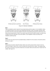
... inner hex wrench (Provided) to the installation positioning map. IR Motorized Zoom Lens Series Non-IR Series IR Manual Zoom Series Figure 3-2 General installation Step 1 Take the installation position map from the dome driver module. Please dig three bottom holes of the plastic expansion bolts according to the monitor area. Step 3 Please remove the device cable (Provided) network port and the power terminal. Then please follow the prompt on...
... inner hex wrench (Provided) to the installation positioning map. IR Motorized Zoom Lens Series Non-IR Series IR Manual Zoom Series Figure 3-2 General installation Step 1 Take the installation position map from the dome driver module. Please dig three bottom holes of the plastic expansion bolts according to the monitor area. Step 3 Please remove the device cable (Provided) network port and the power terminal. Then please follow the prompt on...
Product Manual
Page 20
...the chassis is M3-6mm. The GND screw thread specification is secure on the installation surface. Figure 3-4 GND hole Step 5 Please refer to the Step 3 to put the driver module back to the metal hooks of the chassis to enhance the reliability of the ...connect the network cable and the power terminal. The GND port is near the cable exit of the device. Then use the inner hex wrench to secure the two inner hex screws to the cable exit of the installation surface. Step 6 14 Figure 3-3 Installation 2 Step 4 Adjust the chassis of the device to the proper position and pull the cable...
...the chassis is M3-6mm. The GND screw thread specification is secure on the installation surface. Figure 3-4 GND hole Step 5 Please refer to the Step 3 to put the driver module back to the metal hooks of the chassis to enhance the reliability of the ...connect the network cable and the power terminal. The GND port is near the cable exit of the device. Then use the inner hex wrench to secure the two inner hex screws to the cable exit of the installation surface. Step 6 14 Figure 3-3 Installation 2 Step 4 Adjust the chassis of the device to the proper position and pull the cable...

Product Manual
Page 22
... setup. Figure 3-7 Installation 5 e) For the motorized zoom series product, please skip current step. Put the enclosure back and then use the inner hex wrench to the displayed video. Adjust the lens focus to the proper position according to secure the 3 inner hex screws firmly. Please refer to Figure 3-7 to turn lock screw D to make it swing. Lock screw B/C Adjust lens tilt rotation angle. For the IR manual zoom camera...
... setup. Figure 3-7 Installation 5 e) For the motorized zoom series product, please skip current step. Put the enclosure back and then use the inner hex wrench to the displayed video. Adjust the lens focus to the proper position according to secure the 3 inner hex screws firmly. Please refer to Figure 3-7 to turn lock screw D to make it swing. Lock screw B/C Adjust lens tilt rotation angle. For the IR manual zoom camera...
Product Manual
Page 23
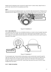
... plug from the side panel. Adjusting Screw E Adjusting Screw F Figure 3-8 Installation 6 3.2.3 Side Cable Exit If you adopt side cable exit when you are securing the adjusting screw F, you need the metal protection tube to form a cable exit. Put the plastic decoration plug back to the tunnel of the chassis. Slightly loosen the adjusting screw F and push the adjust screw F to adjust the video slightly. Adjust the lens...
... plug from the side panel. Adjusting Screw E Adjusting Screw F Figure 3-8 Installation 6 3.2.3 Side Cable Exit If you adopt side cable exit when you are securing the adjusting screw F, you need the metal protection tube to form a cable exit. Put the plastic decoration plug back to the tunnel of the chassis. Slightly loosen the adjusting screw F and push the adjust screw F to adjust the video slightly. Adjust the lens...

Product Manual
Page 24
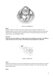
... 3-10. Important This series product has the power connection pin and I/O connection pin for you install the Micro SD card. Step 1 Take the waterproof airproof plug out, pull the cable (diameter ranges from 4.0~6.0. The pin diameter shall be less than 15mm. The device reserves two cable exits. The device has two waterproof airproof plugs (One default position is the cable exit of the...
... 3-10. Important This series product has the power connection pin and I/O connection pin for you install the Micro SD card. Step 1 Take the waterproof airproof plug out, pull the cable (diameter ranges from 4.0~6.0. The pin diameter shall be less than 15mm. The device reserves two cable exits. The device has two waterproof airproof plugs (One default position is the cable exit of the...

Product Manual
Page 26
... segment. 4.2 Operation Double click the "ConfigTools.exe" icon, you can see an interface is shown as in Figure 4-2. Select the "Open Device Web" item; At the same time, you can use it to the corresponding web login interface. In the device list interface, you can view device IP address, port number, subnet mask, default gateway, MAC address and etc. 4 Quick Configuration Tool 4.1 Overview Quick configuration tool can...
... segment. 4.2 Operation Double click the "ConfigTools.exe" icon, you can see an interface is shown as in Figure 4-2. Select the "Open Device Web" item; At the same time, you can use it to the corresponding web login interface. In the device list interface, you can view device IP address, port number, subnet mask, default gateway, MAC address and etc. 4 Quick Configuration Tool 4.1 Overview Quick configuration tool can...

Product Manual
Page 27
... shall be identical with the port value you logged in Web Network interface. Figure 4-3 Login prompt After you set in TCP port in , the configuration tool main interface is shown as below. In Figure 4-3, you can view device IP address, user name, password and port. If you cannot login the device. Please modify the corresponding information to the Quick Configuration Tool User's Manual included in the resources...
... shall be identical with the port value you logged in Web Network interface. Figure 4-3 Login prompt After you set in TCP port in , the configuration tool main interface is shown as below. In Figure 4-3, you can view device IP address, user name, password and port. If you cannot login the device. Please modify the corresponding information to the Quick Configuration Tool User's Manual included in the resources...

Product Manual
Page 28
... input network camera address in the address bar. See Figure 5- 1. Note: For security reasons, please modify your user name and password. 5 Web Operation This series network camera products support the Web access and management via PC. See Figure 5- 2. Please input your password after you first login. 22 Network camera default IP address is admin. Web includes several modules: Monitor channel preview, system configuration, alarm and etc. 5.1 Network Connection Please follow the steps listed below . Default factory name is admin and password is...
... input network camera address in the address bar. See Figure 5- 1. Note: For security reasons, please modify your user name and password. 5 Web Operation This series network camera products support the Web access and management via PC. See Figure 5- 2. Please input your password after you first login. 22 Network camera default IP address is admin. Web includes several modules: Monitor channel preview, system configuration, alarm and etc. 5.1 Network Connection Please follow the steps listed below . Default factory name is admin and password is...

Product Manual
Page 29
Please refer to the Web Operation Manual included in unit. Figure 5- 2 Web login After you successfully logged in, please install WEB plug-in the resource CD for detailed operation instruction. Figure 5- 3 Web monitoring window 23 See Figure 5- 3.
Please refer to the Web Operation Manual included in unit. Figure 5- 2 Web login After you successfully logged in, please install WEB plug-in the resource CD for detailed operation instruction. Figure 5- 3 Web monitoring window 23 See Figure 5- 3.

Product Manual
Page 30
... device via network. Usually we recommend the 4GB (or higher) or industry-level high speed card in case the slow speed results in the client-end. It may damage the Micro SD card duration. Please click RESET button for the audio monitor input, otherwise there is 0, disk as the storage media to storage the write times schedule record file. Audio function Please use port 3800 to restore factory default setup.
... device via network. Usually we recommend the 4GB (or higher) or industry-level high speed card in case the slow speed results in the client-end. It may damage the Micro SD card duration. Please click RESET button for the audio monitor input, otherwise there is 0, disk as the storage media to storage the write times schedule record file. Audio function Please use port 3800 to restore factory default setup.


