

Datasheet
Page 1
... meant for the Video Management System Software and database. Designed for 24 / 7 / 365 operation, it includes 4 Gigabit Ethernet ports and a built-in Revision 1.1; ICM-7100SE IC Realtime Central Management 1U Server The ICM-7100 series server is your various remote video devices and locations. This dedicated Linux server uses a Client / Server topology for up to 1,000 cameras, requires an unlimited amount of user accounts, or needs a single point to software licenses from other...
... meant for the Video Management System Software and database. Designed for 24 / 7 / 365 operation, it includes 4 Gigabit Ethernet ports and a built-in Revision 1.1; ICM-7100SE IC Realtime Central Management 1U Server The ICM-7100 series server is your various remote video devices and locations. This dedicated Linux server uses a Client / Server topology for up to 1,000 cameras, requires an unlimited amount of user accounts, or needs a single point to software licenses from other...

Datasheet
Page 2
ICM-7100SE Specifications Model Main Processor OS Memory Chassis Network Port Ethernet Port RS232 RS485 Alarm Input / Output USB Port HDMI VGA HDD Installation Connected cameras per server Clients per system Number of users Number of roles Video Input Bandwidth Video Output Bandwidth Video Storage Bandwidth Alarm Inputs Power Consumption Working Temp Working Humidity Storage Temp Storage Humidity Working Altitude Weight Dimensions (W×D×H) Installation Method ICM-7100SE System 64 bit Quad core CPU Embedded LINUX 4GB 1.0mm SGCC steel plate Interface 4 RJ-45 Ports (10...
ICM-7100SE Specifications Model Main Processor OS Memory Chassis Network Port Ethernet Port RS232 RS485 Alarm Input / Output USB Port HDMI VGA HDD Installation Connected cameras per server Clients per system Number of users Number of roles Video Input Bandwidth Video Output Bandwidth Video Storage Bandwidth Alarm Inputs Power Consumption Working Temp Working Humidity Storage Temp Storage Humidity Working Altitude Weight Dimensions (W×D×H) Installation Method ICM-7100SE System 64 bit Quad core CPU Embedded LINUX 4GB 1.0mm SGCC steel plate Interface 4 RJ-45 Ports (10...

Product Manual
Page 11
... speed dome link Access control, alarm controller arm/disarm Behavior analysis, people count, heat map. DSS platform support download, installation and usage of playback record E-map function allows user to position the device at any time. Audio intercom allows client to communicate with front-end device and broadcast. Video intercom, remote unlock and talk Easy management and Control TV Wall display synchronously. Customize...
... speed dome link Access control, alarm controller arm/disarm Behavior analysis, people count, heat map. DSS platform support download, installation and usage of playback record E-map function allows user to position the device at any time. Audio intercom allows client to communicate with front-end device and broadcast. Video intercom, remote unlock and talk Easy management and Control TV Wall display synchronously. Customize...

Product Manual
Page 14
... . While, under planning of Ethernet port: Ethernet port 1 as server communication, port 2 as reserved, port 3 and 4 as ISCSI storage. Load balancing: known as multi-Ethernet card mode, you click Skip, the system will operate according to master device. This mode only provides fault tolerant function; Figure 2- 4 3. Viewing from hot spare to current IP and perform next config. Configure IP address, router address and each type of high...
... . While, under planning of Ethernet port: Ethernet port 1 as server communication, port 2 as reserved, port 3 and 4 as ISCSI storage. Load balancing: known as multi-Ethernet card mode, you click Skip, the system will operate according to master device. This mode only provides fault tolerant function; Figure 2- 4 3. Viewing from hot spare to current IP and perform next config. Configure IP address, router address and each type of high...

Product Manual
Page 15
... configures hot spare, when master server goes down, hot spare server will enable database ( mysql server ) , tomcat and CMS and etc. Master/slave server selection. Role of related Ethernet port. When master server recovers, the system will switch back to user which manage data, device and dispatch other distribution work. Figure 2- 6 Note: Server in WAN address and port info of distribute server includes device input+forward+storage, only enable corresponding...
... configures hot spare, when master server goes down, hot spare server will enable database ( mysql server ) , tomcat and CMS and etc. Master/slave server selection. Role of related Ethernet port. When master server recovers, the system will switch back to user which manage data, device and dispatch other distribution work. Figure 2- 6 Note: Server in WAN address and port info of distribute server includes device input+forward+storage, only enable corresponding...

Product Manual
Page 18
... be used as normal, see Figure 2- 12. Select one slave server, click button, the system pops up edit box, see Figure 2- 14. Figure 2- 14 When distribute server goes down, redundant server will replace it in "Enable" column, enable button, and after server reboots, Server Status shows which means that slave server can see Figure 2- 13. Figure 2- 13 After set redundant server, you may view...
... be used as normal, see Figure 2- 12. Select one slave server, click button, the system pops up edit box, see Figure 2- 14. Figure 2- 14 When distribute server goes down, redundant server will replace it in "Enable" column, enable button, and after server reboots, Server Status shows which means that slave server can see Figure 2- 13. Figure 2- 13 After set redundant server, you may view...

Product Manual
Page 19
... distribute server can also be played. When distribute server recovers, you can manually move back device to view info in both slave server and redundant server. 9 Grey means disabled. Server Type: highlight means that it is working, the record originally saved on slave server can search and playback record in home server mounted by redundant server and current operation status. Click button next to redundant server, to original slave server. See...
... distribute server can also be played. When distribute server recovers, you can manually move back device to view info in both slave server and redundant server. 9 Grey means disabled. Server Type: highlight means that it is working, the record originally saved on slave server can search and playback record in home server mounted by redundant server and current operation status. Click button next to redundant server, to original slave server. See...

Product Manual
Page 22
... server IP and CMS port (by default). Stream type: self-adaptive, main stream and sub stream. Auto register device: need to change. To prevent this situation, when you directly write server IP, then when the server goes down, redundant server will replace, and the Auto register device cannot register to lock center record; Self-adaptive: when access client, according to client setup, stream self adapts to fill in port...
... server IP and CMS port (by default). Stream type: self-adaptive, main stream and sub stream. Auto register device: need to change. To prevent this situation, when you directly write server IP, then when the server goes down, redundant server will replace, and the Auto register device cannot register to lock center record; Self-adaptive: when access client, according to client setup, stream self adapts to fill in port...

Product Manual
Page 24
... modification: login config account, modify login password. System maintain: support to reboot, shut down and restore. Reset password: reset backstage config/system/root user login password. Time setup Function in Figure 2- 24. Restore default: it will clear database and restore default status. Default is config item of video talk server. PTS server Picture storage server port, 8081 by default. Figure 2- 24 Server address: server IP, port is 5080 by default. SCS server SCS server config...
... modification: login config account, modify login password. System maintain: support to reboot, shut down and restore. Reset password: reset backstage config/system/root user login password. Time setup Function in Figure 2- 24. Restore default: it will clear database and restore default status. Default is config item of video talk server. PTS server Picture storage server port, 8081 by default. Figure 2- 24 Server address: server IP, port is 5080 by default. SCS server SCS server config...

Product Manual
Page 28
... real-time operation status. Figure 2- 38 18 Figure 2- 35 For the added storage server, it to video or picture, same as "local disk config", see prompt, click OK. means normal, means abnormal, see Figure 2- 36. After you add it, you must format this disk to use this disk, and set it has been added and used by other server, then the Raid group info...
... real-time operation status. Figure 2- 38 18 Figure 2- 35 For the added storage server, it to video or picture, same as "local disk config", see prompt, click OK. means normal, means abnormal, see Figure 2- 36. After you add it, you must format this disk to use this disk, and set it has been added and used by other server, then the Raid group info...

Product Manual
Page 54
... can be open. In device list on the right, select channel and double click or drag it to snapshot. If you double click device, then all channels under Setup Manager area. System shows Live Preview interface. to video window. Record and snapshot Right click video window, select TV wall. You can click in Live Preview, and the other is to select window decoding in video window to...
... can be open. In device list on the right, select channel and double click or drag it to snapshot. If you double click device, then all channels under Setup Manager area. System shows Live Preview interface. to video window. Record and snapshot Right click video window, select TV wall. You can click in Live Preview, and the other is to select window decoding in video window to...

Product Manual
Page 59
... open local record storage path. Step 5. Login DSS Manager. Step 2. Click Add. Step 3. Double click record, you can view detailed info of picture. System pops up Add Encoder box, see Figure 5-12. 49 Right click searched picture or record, you can copy, cut and delete the picture or record. Double click picture, you can view detailed info of record and playback the record. Select General>Device>Device. Step 4. Click Local Record...
... open local record storage path. Step 5. Login DSS Manager. Step 2. Click Add. Step 3. Double click record, you can view detailed info of picture. System pops up Add Encoder box, see Figure 5-12. 49 Right click searched picture or record, you can copy, cut and delete the picture or record. Double click picture, you can view detailed info of record and playback the record. Select General>Device>Device. Step 4. Click Local Record...

Product Manual
Page 61
... into 8 scenes. You can set tour task: Step 1. System displays Tour Task interface. Click . Step 3. System displays add task interface. Figure 5-13 The fisheye in Setup Manager area. To set tour task to left window for setup as : , and its corresponding box will rotate. Input Task Name, Description and select Window No. Step 4. Drag designated device on the right to achieve...
... into 8 scenes. You can set tour task: Step 1. System displays Tour Task interface. Click . Step 3. System displays add task interface. Figure 5-13 The fisheye in Setup Manager area. To set tour task to left window for setup as : , and its corresponding box will rotate. Input Task Name, Description and select Window No. Step 4. Drag designated device on the right to achieve...

Product Manual
Page 69
... list, click Pattern. Click Setup>Start Record, operate 8 PTZ buttons, to start rotation according to start setup of pattern. System shows Device interface. Step 2. In dropdown list, select pattern number, you can see Figure 5-22. 59 Click Startup to setup....need to platform. Login DSS Manager. Pattern is complete. Click Setup>Stop Record, setup is the path of POS. Warning Current POS info are all connected to NVR, and sent to DSS Platform for storage via NVR later, so you can add NVR supporting POS. Install POS into conversion box, and match conversion box...
... list, click Pattern. Click Setup>Start Record, operate 8 PTZ buttons, to start rotation according to start setup of pattern. System shows Device interface. Step 2. In dropdown list, select pattern number, you can see Figure 5-22. 59 Click Startup to setup....need to platform. Login DSS Manager. Pattern is complete. Click Setup>Stop Record, setup is the path of POS. Warning Current POS info are all connected to NVR, and sent to DSS Platform for storage via NVR later, so you can add NVR supporting POS. Install POS into conversion box, and match conversion box...

Product Manual
Page 88
In the grid draw motion detection area , and click . Step 2. After videos are searched, double click to playback, such as wall mount, see Figure 6-14. Step 3. The system searches motion detection result within the area, and the playback channel is purple, see Figure 6-15. 78 Click Playback, enter Playback interface. Step 1. On the right, click fisheye device and set time, click Search. Right click and select video mode of fisheye to open record. Figure 6-14 6.2.3 Fisheye Playback Record The system supports to playback central record in fisheye device.
In the grid draw motion detection area , and click . Step 2. After videos are searched, double click to playback, such as wall mount, see Figure 6-14. Step 3. The system searches motion detection result within the area, and the playback channel is purple, see Figure 6-15. 78 Click Playback, enter Playback interface. Step 1. On the right, click fisheye device and set time, click Search. Right click and select video mode of fisheye to open record. Figure 6-14 6.2.3 Fisheye Playback Record The system supports to playback central record in fisheye device.

Product Manual
Page 112
..., Video Loss, Tampering, Video Analytics. Set alarm delay time. Set snapshot channel. 102 Directly login device web end, or go to set alarm source on device first. Step 3. Select alarm output. Open EVENT tab. For example, make Motion Detect as an example. Select alarm video output. See Figure 8-1. Set monitoring zone. Different devices need to DSS Manager-end Device interface>NVR device tab, click . Here makes NVR an example and introduces web config steps. 8.1 Device-end...
..., Video Loss, Tampering, Video Analytics. Set alarm delay time. Set snapshot channel. 102 Directly login device web end, or go to set alarm source on device first. Step 3. Select alarm output. Open EVENT tab. For example, make Motion Detect as an example. Select alarm video output. See Figure 8-1. Set monitoring zone. Different devices need to DSS Manager-end Device interface>NVR device tab, click . Here makes NVR an example and introduces web config steps. 8.1 Device-end...

Product Manual
Page 171
... You can directly talk to device on device to search and playback pattern of device record and center record. Figure 12-21 Record playback supports search and playback of current device. GPS: display current device GPS info and pattern. Device, display current device record. Platform, display current platform central record (record in record plan). Configure start time and end time. Step 3. Step 2. Select GPS. Select one of GPS, device and platform to select record playback function, see...
... You can directly talk to device on device to search and playback pattern of device record and center record. Figure 12-21 Record playback supports search and playback of current device. GPS: display current device GPS info and pattern. Device, display current device record. Platform, display current platform central record (record in record plan). Configure start time and end time. Step 3. Step 2. Select GPS. Select one of GPS, device and platform to select record playback function, see...
Product Manual
Page 195
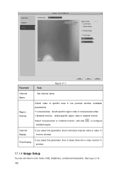
...-7 Channel Name Set channel name. See Figure 17-8. 185 Available parameters: Local preview:shield specific region video in local preview video. Network monitor:shield specific region video in video 如 monitor window. If you select this parameter, then it will show channel name in network monitor. Region Overlay Shield video of specific area in video monitor 如 Time Display window. 17.1.4 Image Setup You can set video's color mode...
...-7 Channel Name Set channel name. See Figure 17-8. 185 Available parameters: Local preview:shield specific region video in local preview video. Network monitor:shield specific region video in video 如 monitor window. If you select this parameter, then it will show channel name in network monitor. Region Overlay Shield video of specific area in video monitor 如 Time Display window. 17.1.4 Image Setup You can set video's color mode...

Product Manual
Page 210
... address button on remote control and enter remote control address and device no . Pack Duration Set pack duration of device. Device no . Video Standard Show video standard of each record file. 17.4.2 System Maintenance 17.4.2.1 Local Setup See Figure 17-22. Language Show device system language. Device No. Parameter Note Figure 17-22 Device Name Set device name. Default is full, it stops record. Overwrite, when current disk is 60 minutes. Used to in remote control...
... address button on remote control and enter remote control address and device no . Pack Duration Set pack duration of device. Device no . Video Standard Show video standard of each record file. 17.4.2 System Maintenance 17.4.2.1 Local Setup See Figure 17-22. Language Show device system language. Device No. Parameter Note Figure 17-22 Device Name Set device name. Default is full, it stops record. Overwrite, when current disk is 60 minutes. Used to in remote control...

Product Manual
Page 212
....4.2.6 Firmware Upgrade 202 Stop Bit Default is "115200". overlaps, you need to set to this COM. Network keyboard, via COM use professional keyboard to contol device. Transparent COM, use professional keyboard to delete file, see Figure 17-25. Select corresponding serial control protocol, serial function control protocol have: General, use COM and mini terminal software to upgrade and debug. Control keyboard, via Ethernet port use to connect...
....4.2.6 Firmware Upgrade 202 Stop Bit Default is "115200". overlaps, you need to set to this COM. Network keyboard, via COM use professional keyboard to contol device. Transparent COM, use professional keyboard to delete file, see Figure 17-25. Select corresponding serial control protocol, serial function control protocol have: General, use COM and mini terminal software to upgrade and debug. Control keyboard, via Ethernet port use to connect...


