
Instruction Manual
Page 1
INSTRUCTION MANUAL VHF AIR BAND TRANSCEIVER iA110 This device complies with Part 15 of the FCC Rules. Operation is subject to the condition that this device does not cause harmful interference.
INSTRUCTION MANUAL VHF AIR BAND TRANSCEIVER iA110 This device complies with Part 15 of the FCC Rules. Operation is subject to the condition that this device does not cause harmful interference.

Instruction Manual
Page 2
... polarity. struction manual contains important operating instructions for the IC-A110. EXPLICIT DEFINITIONS R WARNING! NEVER connect the transceiver to a power source of personal injury, re or electric shock. NEVER operate the transceiver with a headset or other audio accessories at more than 5 A. If you experience a ringing in - i NEVER connect the transceiver to an AC outlet or to a power source that is DC fused at high volume levels. Accidental...
... polarity. struction manual contains important operating instructions for the IC-A110. EXPLICIT DEFINITIONS R WARNING! NEVER connect the transceiver to a power source of personal injury, re or electric shock. NEVER operate the transceiver with a headset or other audio accessories at more than 5 A. If you experience a ringing in - i NEVER connect the transceiver to an AC outlet or to a power source that is DC fused at high volume levels. Accidental...

Instruction Manual
Page 3
... Function display 3 2 BASIC OPERATION 4 - 5 I Power ON 4 I Channel selection 4 I Squelch function 5 I Side tone function 5 I LCD backlight control 5 I Dial select function 5 3 SCAN OPERATION 6 - 7 I Scan operation 6 I On-hook scan 7 I Dualwatch 7 4 MEMORY PROGRAMMING 8 - 9 I Programming a memory channel 8 I Memory names 9 5 OTHER FUNCTIONS 10-11 I Initial set mode 10-11 6 CONNECTION AND INSTALLATION 12 - 13 I Rear panel and connections 12 I Mounting 13 I Supplied accessories 13 7 CLONING 14 8 SPECIFICATIONS 15-16 9 OPC-871 HEADSET ADAPTER 17-18 I OPC-871 Headset adapter...
... Function display 3 2 BASIC OPERATION 4 - 5 I Power ON 4 I Channel selection 4 I Squelch function 5 I Side tone function 5 I LCD backlight control 5 I Dial select function 5 3 SCAN OPERATION 6 - 7 I Scan operation 6 I On-hook scan 7 I Dualwatch 7 4 MEMORY PROGRAMMING 8 - 9 I Programming a memory channel 8 I Memory names 9 5 OTHER FUNCTIONS 10-11 I Initial set mode 10-11 6 CONNECTION AND INSTALLATION 12 - 13 I Rear panel and connections 12 I Mounting 13 I Supplied accessories 13 7 CLONING 14 8 SPECIFICATIONS 15-16 9 OPC-871 HEADSET ADAPTER 17-18 I OPC-871 Headset adapter...

Instruction Manual
Page 4
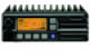
...]; 1 MHz or 10 kHz are available at power ON as options: • Initial set mode, etc. ➥ Push to toggle the dimmer control OFF, Low and High. ➥ Push and hold 500 m sec. 1 PANEL DESCRIPTION I Panel description q w e r V/M SCAN PRI SQL !0 o i u y t q TUNING [DIAL(TS)] ➥Changes the operating frequency; t POWER SWITCH [POWER] Push and hold for 1 sec. memory channel in set mode (p. 10) • Cloning mode (p. 14) 1 w FUNCTION DISPLAY (p. 3) Displays...
...]; 1 MHz or 10 kHz are available at power ON as options: • Initial set mode, etc. ➥ Push to toggle the dimmer control OFF, Low and High. ➥ Push and hold 500 m sec. 1 PANEL DESCRIPTION I Panel description q w e r V/M SCAN PRI SQL !0 o i u y t q TUNING [DIAL(TS)] ➥Changes the operating frequency; t POWER SWITCH [POWER] Push and hold for 1 sec. memory channel in set mode (p. 10) • Cloning mode (p. 14) 1 w FUNCTION DISPLAY (p. 3) Displays...
Instruction Manual
Page 5
... connect other microphones. The pin assignments may be different and the transceiver may be damaged. u PRIORITY SWITCH [PRI] Push to set the displayed channel as a memory lock-out channel. (p. 8) • "LOCK OUT" appears on the display. Please contact your dealer for 5 sec. PANEL DESCRIPTION 1 y SQL SWITCH [SQL] ➥ Push to turn on the squelch adjust mode. (p. 6) ➥ Push and hold this switch for 5 sec. i SCAN SWITCH [SCAN] ➥ Starts and stops...
... connect other microphones. The pin assignments may be different and the transceiver may be damaged. u PRIORITY SWITCH [PRI] Push to set the displayed channel as a memory lock-out channel. (p. 8) • "LOCK OUT" appears on the display. Please contact your dealer for 5 sec. PANEL DESCRIPTION 1 y SQL SWITCH [SQL] ➥ Push to turn on the squelch adjust mode. (p. 6) ➥ Push and hold this switch for 5 sec. i SCAN SWITCH [SCAN] ➥ Starts and stops...

Instruction Manual
Page 6
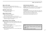
r BUSY INDICATOR (p. 6) "BUSY" appears when receiving a signal or when the squelch is selected. o i u i SET MODE INDICATOR ➥ Appears when the Initial set as a 'LOCK OUT' chan- e SCAN INDICATOR (p. 8) Indicates when the scan function is open. (p. 6) *NOTE: The VFO/memory switch [V/M] and the memory write switch [M/W] functions may not be available depending on version. 3 nel. (p. 8) !0 MEMORY CHANNEL INDICATOR ➥ Indicates the selected memory channel number ➥ 'Pr' appears...
r BUSY INDICATOR (p. 6) "BUSY" appears when receiving a signal or when the squelch is selected. o i u i SET MODE INDICATOR ➥ Appears when the Initial set as a 'LOCK OUT' chan- e SCAN INDICATOR (p. 8) Indicates when the scan function is open. (p. 6) *NOTE: The VFO/memory switch [V/M] and the memory write switch [M/W] functions may not be available depending on version. 3 nel. (p. 8) !0 MEMORY CHANNEL INDICATOR ➥ Indicates the selected memory channel number ➥ 'Pr' appears...

Instruction Manual
Page 7
... point. • Push [SQL] to adjust the squelch level. (p. 6) • Push and hold [SQL] for 1 sec. 2 BASIC OPERATION I Channel selection ï VFO/Memory selection q Push [V/M] to select memory mode or VFO mode. ➥ Rotate the dial to select a desired frequency/channel. crophone. • Transmit indicator lights. tions. t Release [PTT] to transmit, then speak into the mi- w Operate the transceiver as indicated in the following...
... point. • Push [SQL] to adjust the squelch level. (p. 6) • Push and hold [SQL] for 1 sec. 2 BASIC OPERATION I Channel selection ï VFO/Memory selection q Push [V/M] to select memory mode or VFO mode. ➥ Rotate the dial to select a desired frequency/channel. crophone. • Transmit indicator lights. tions. t Release [PTT] to transmit, then speak into the mi- w Operate the transceiver as indicated in the following...

Instruction Manual
Page 8
... the display. OFF, Low or High are available. w Turn the tuning [DIAL] to select VFO mode. use 1 MHz tuning when you want to the headset for normal operation. 5 via the OPC-871 HEAD SET ADAPTOR, the transceiver outputs your transmitted voice to change the frequency in large increments; e Push [SQL] to return to mute undesired noise while receiving no signal. D Setting the squelch level q Push [SQL] to change the frequency in...
... the display. OFF, Low or High are available. w Turn the tuning [DIAL] to select VFO mode. use 1 MHz tuning when you want to the headset for normal operation. 5 via the OPC-871 HEAD SET ADAPTOR, the transceiver outputs your transmitted voice to change the frequency in large increments; e Push [SQL] to return to mute undesired noise while receiving no signal. D Setting the squelch level q Push [SQL] to change the frequency in...
Instruction Manual
Page 9
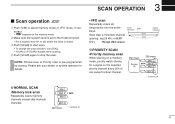
... SCAN •Memory lock scan Repeatedly scans memory channels except skip (lockout) channels. 3 SCAN OPERATION I Scan operation q Push [V/M] to select memory mode or VFO mode, if necessary. • " MR " appears on the selected priority channel every 250 m sec except lockout channel. 250 msec. 250 msec. Scan step is pre-programmed by cloning. Mch 1 Mch 2* SKIP Mch 3 Mch 20 250 msec. *: Lockout ch 6 w Make sure the squelch level is set to...
... SCAN •Memory lock scan Repeatedly scans memory channels except skip (lockout) channels. 3 SCAN OPERATION I Scan operation q Push [V/M] to select memory mode or VFO mode, if necessary. • " MR " appears on the selected priority channel every 250 m sec except lockout channel. 250 msec. 250 msec. Scan step is pre-programmed by cloning. Mch 1 Mch 2* SKIP Mch 3 Mch 20 250 msec. *: Lockout ch 6 w Make sure the squelch level is set to...

Instruction Manual
Page 10
... and hold PTT. 250 msec. e Place the microphone on the hook to memory channel. ➥ • In priority memory scan; r Scan restarts 2 sec. When you did not converse the station. VFO frequency or memory channel ï Operation qSelect the desired operating channel (VFO or Memory channel). to frequency. ➥ • In memory scan; 3 SCAN OPERATION I Dualwatch Dualwatch monitors priority channel while you are receiving an other channel (VFO or...
... and hold PTT. 250 msec. e Place the microphone on the hook to memory channel. ➥ • In priority memory scan; r Scan restarts 2 sec. When you did not converse the station. VFO frequency or memory channel ï Operation qSelect the desired operating channel (VFO or Memory channel). to frequency. ➥ • In memory scan; 3 SCAN OPERATION I Dualwatch Dualwatch monitors priority channel while you are receiving an other channel (VFO or...
Instruction Manual
Page 11
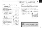
... frequency. • Push [DIAL/TS] one or more times to select the desired memory channel number. e Push [V/M] for 1 sec. r Turn the [DIAL] to use the dial select function, if desired. Memory channel 8 is set as lock out channel. *NOTE: The VFO/memory switch [V/M] and the memory write switch [M/W] functions may not be scanned as a lock out channel. q Push [V/M] to enter memory programming mode. • " MR " and memory channel number...
... frequency. • Push [DIAL/TS] one or more times to select the desired memory channel number. e Push [V/M] for 1 sec. r Turn the [DIAL] to use the dial select function, if desired. Memory channel 8 is set as lock out channel. *NOTE: The VFO/memory switch [V/M] and the memory write switch [M/W] functions may not be scanned as a lock out channel. q Push [V/M] to enter memory programming mode. • " MR " and memory channel number...

Instruction Manual
Page 12
...;Push PTT switch to abort the programming memory name. • The following characters can be used in length. • When no name is programmed, the display shows the operating frequency. [EXAMPLE]: Setting the name to " TOWER 2" V/M for 5 sec. to input the set name. • Flashing stops. • Memory channels can be programmed: ➥ Push [V/M] to select memory mode. ➥ Turns [DIAL] to Z (capitals), (space and `. e Turns the...
...;Push PTT switch to abort the programming memory name. • The following characters can be used in length. • When no name is programmed, the display shows the operating frequency. [EXAMPLE]: Setting the name to " TOWER 2" V/M for 5 sec. to input the set name. • Flashing stops. • Memory channels can be programmed: ➥ Push [V/M] to select memory mode. ➥ Turns [DIAL] to Z (capitals), (space and `. e Turns the...

Instruction Manual
Page 13
... beep tones normally sound when you prefer. These can "customize" transceiver operations to suit your transmitted voice to turn power ON. • The transceiver enters initial set mode and select the previous operating mode. D Side tones ON/OFF When using an optional headset such as described below and at power ON and allows you to display a memory name instead of frequency. • When a memory channel has not been programmed with a name, frequency...
... beep tones normally sound when you prefer. These can "customize" transceiver operations to suit your transmitted voice to turn power ON. • The transceiver enters initial set mode and select the previous operating mode. D Side tones ON/OFF When using an optional headset such as described below and at power ON and allows you to display a memory name instead of frequency. • When a memory channel has not been programmed with a name, frequency...
Instruction Manual
Page 14
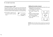
... priority channel set mode. In addition the priority channel is used to store your most often-used channel for the priority channel will differ depending on pre-programming. ➥ Push [PRI] to toggle the priority channel mode or previous mode. • Setting the priority channel qWhile pushing and holding [V/M] and [DIAL(TS)], push [POWER] to turn the power ON. • The transceiver enters initial set mode. e Select the desired channel number as...
... priority channel set mode. In addition the priority channel is used to store your most often-used channel for the priority channel will differ depending on pre-programming. ➥ Push [PRI] to toggle the priority channel mode or previous mode. • Setting the priority channel qWhile pushing and holding [V/M] and [DIAL(TS)], push [POWER] to turn the power ON. • The transceiver enters initial set mode. e Select the desired channel number as...

Instruction Manual
Page 15
red: , 12 V or 24 V Battery q Connects to an antenna Ask your dealer about antenna selection and best installation location. (Standard 50 Ω antenna with a SWR 6 CONNECTION AND INSTALLATION I Rear panel and connections › External speaker jack ⁄ Antenna ¤ fi OPC-871 HEADSET ADAPTER (Option) ‹ Supplied DC power cable black: .
red: , 12 V or 24 V Battery q Connects to an antenna Ask your dealer about antenna selection and best installation location. (Standard 50 Ω antenna with a SWR 6 CONNECTION AND INSTALLATION I Rear panel and connections › External speaker jack ⁄ Antenna ¤ fi OPC-871 HEADSET ADAPTER (Option) ‹ Supplied DC power cable black: .

Instruction Manual
Page 16
w Microphone hanger and screw set 1 set e Microphone cable 1 r DC power cable (OPC-344 1 t Mounting bracket 1 y Bracket bolts 4 u Mounting screws (M5 × 12 4 i Self-tapping screws (M5 × 20 4 o Flat washers 4 !0 Spring washers 4 !1 Nuts 4 !2 Fuses (10 A 2 13 6 CONNECTION AND INSTALLATION I Mounting I Supplied accessories Flat washer Spring washer 1 2 4 3 When using self-tapping screws The universal mounting bracket supplied with the 4 supplied screws (M5 ×...
w Microphone hanger and screw set 1 set e Microphone cable 1 r DC power cable (OPC-344 1 t Mounting bracket 1 y Bracket bolts 4 u Mounting screws (M5 × 12 4 i Self-tapping screws (M5 × 20 4 o Flat washers 4 !0 Spring washers 4 !1 Nuts 4 !2 Fuses (10 A 2 13 6 CONNECTION AND INSTALLATION I Mounting I Supplied accessories Flat washer Spring washer 1 2 4 3 When using self-tapping screws The universal mounting bracket supplied with the 4 supplied screws (M5 ×...
Instruction Manual
Page 17
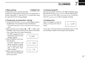
... and cloning must be cloned to and from PC to a transceiver using the optional CS-A110 cloning software. 7 CLONING D Data cloning ] Cloning allows you to quickly and easily transfer the programmed contents from one transceiver to another transceiver, or, data from a PC (IBM compatible) using the optional CS-A110 CLONING SOFTWARE and the optional OPC478 CLONING CABLE+ OPC-592 CLONING CABLE ADAPTER. w While pushing and holding [Y] + [Z] + [V/M], push [POWER] ON to enter cloning mode (master transceiver only-power ON...
... and cloning must be cloned to and from PC to a transceiver using the optional CS-A110 cloning software. 7 CLONING D Data cloning ] Cloning allows you to quickly and easily transfer the programmed contents from one transceiver to another transceiver, or, data from a PC (IBM compatible) using the optional CS-A110 CLONING SOFTWARE and the optional OPC478 CLONING CABLE+ OPC-592 CLONING CABLE ADAPTER. w While pushing and holding [Y] + [Z] + [V/M], push [POWER] ON to enter cloning mode (master transceiver only-power ON...
Instruction Manual
Page 18
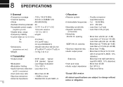
...% distortion) • Output power : 36 W (pep) typical Side tone More than 1 µV (pd) (negative ground) *Automatic selection • Usable temp. 8 SPECIFICATIONS D General D Receiver • Frequency coverage : 118 to 136.975 MHz • Receive system : Double conversion • Channel spacing : 25 kHz or 25/8.33* kHz superheterodyne • Mode : AM (6K00A3E) • Intermediate frequencies : 1st 38.85 MHz • Number of memory channels : 20 2nd...
...% distortion) • Output power : 36 W (pep) typical Side tone More than 1 µV (pd) (negative ground) *Automatic selection • Usable temp. 8 SPECIFICATIONS D General D Receiver • Frequency coverage : 118 to 136.975 MHz • Receive system : Double conversion • Channel spacing : 25 kHz or 25/8.33* kHz superheterodyne • Mode : AM (6K00A3E) • Intermediate frequencies : 1st 38.85 MHz • Number of memory channels : 20 2nd...

Instruction Manual
Page 20
... required. via the adapter, the transceiver outputs your transmitted voice to the headset for monitoring. (pgs. 5, 10) D Connection PTT switch Use a PTT switch with 2 supplied screws. (Fig. 3) HEADSET (Must be purchased separately.) 17 Fig. 1 wUnscrew the 4 screws, then remove the bottom cover. (Fig. 1) e Insert the connector as those from the David Clark Co. D Installation The optional OPC-871 HEADSET ADAPTER install as follows. q Turns the power OFF, then disconnect the DC power cable.
... required. via the adapter, the transceiver outputs your transmitted voice to the headset for monitoring. (pgs. 5, 10) D Connection PTT switch Use a PTT switch with 2 supplied screws. (Fig. 3) HEADSET (Must be purchased separately.) 17 Fig. 1 wUnscrew the 4 screws, then remove the bottom cover. (Fig. 1) e Insert the connector as those from the David Clark Co. D Installation The optional OPC-871 HEADSET ADAPTER install as follows. q Turns the power OFF, then disconnect the DC power cable.

Instruction Manual
Page 22
... channels, scan settings, etc., via a PC. 10 OPTIONS D Other options OPC-871 HEADSET ADAPTER (See pgs. 17-18) CS-A110 CLONING SOFTWARE Provides quick and easy programming of programmed contents from one set and provide a quick and easy programming of items, including memory channels, memory names and set mode contents, etc. OPC-478 CLONING CABLE OPC-592 CLONING CABLE ADAPTOR These three components work as one transceiver to transceiver. OPC-591 CLONING CABLE Cloning cable for transceiver...
... channels, scan settings, etc., via a PC. 10 OPTIONS D Other options OPC-871 HEADSET ADAPTER (See pgs. 17-18) CS-A110 CLONING SOFTWARE Provides quick and easy programming of programmed contents from one set and provide a quick and easy programming of items, including memory channels, memory names and set mode contents, etc. OPC-478 CLONING CABLE OPC-592 CLONING CABLE ADAPTOR These three components work as one transceiver to transceiver. OPC-591 CLONING CABLE Cloning cable for transceiver...


