

Instruction Manual
Page 2
... in RF exposure levels exceeding the FCC requirements for use the Icom belt-clip which persons are exposed as this radio. Belt Clip (MB-98), Rechargeable Li-Ion Battery Pack (BP-227), Alkaline Battery Case (BP-226) and Speaker-microphone (HM-138). You can cause FCC RF exposure compliance requirements to one side. Occupational/Controlled Use The radio transmitter is transmitting when the "TX indicator" lights red. ii
... in RF exposure levels exceeding the FCC requirements for use the Icom belt-clip which persons are exposed as this radio. Belt Clip (MB-98), Rechargeable Li-Ion Battery Pack (BP-227), Alkaline Battery Case (BP-226) and Speaker-microphone (HM-138). You can cause FCC RF exposure compliance requirements to one side. Occupational/Controlled Use The radio transmitter is transmitting when the "TX indicator" lights red. ii

Instruction Manual
Page 3
... transmitting. FCC caution: Changes or modifications to this transceiver under FCC regulations. SAVE THIS INSTRUCTION MANUAL- Equipment damage may occur. Keep the antenna at least 2.5 centimeters (1 inch) from the lips and the transceiver is 5 to 10 cm (2 to the transceiver. NEVER operate the transceiver with its microphone 5 to 10 centimeters (2 to transmit. NEVER connect the transceiver to , or touching exposed parts of the battery pack. Such a connection...
... transmitting. FCC caution: Changes or modifications to this transceiver under FCC regulations. SAVE THIS INSTRUCTION MANUAL- Equipment damage may occur. Keep the antenna at least 2.5 centimeters (1 inch) from the lips and the transceiver is 5 to 10 cm (2 to the transceiver. NEVER operate the transceiver with its microphone 5 to 10 centimeters (2 to transmit. NEVER connect the transceiver to , or touching exposed parts of the battery pack. Such a connection...

Instruction Manual
Page 4
... OPERATION 19-34 ' Default setting 19 ' Receiving a call 20 ' Transmitting a call 23 ' Receiving a message 26 ' Transmitting a status 29 ' Transmitting an SDM 30 ' Position data transmission 31 ' Printer connection 32 ' PC connection 32 ' Digital ANI 32 ' Auto emergency transmission 33 ' Stun function 33 ' BIIS indication 34 ' Priority A channel selection 34 v 5 BATTERY CHARGING 35-44 ' Battery charging 35 ' Caution 36 ' Optional battery chargers 37 ' Optional battery case 43 6 SPEAKER-MICROPHONE 45...
... OPERATION 19-34 ' Default setting 19 ' Receiving a call 20 ' Transmitting a call 23 ' Receiving a message 26 ' Transmitting a status 29 ' Transmitting an SDM 30 ' Position data transmission 31 ' Printer connection 32 ' PC connection 32 ' Digital ANI 32 ' Auto emergency transmission 33 ' Stun function 33 ' BIIS indication 34 ' Priority A channel selection 34 v 5 BATTERY CHARGING 35-44 ' Battery charging 35 ' Caution 36 ' Optional battery chargers 37 ' Optional battery case 43 6 SPEAKER-MICROPHONE 45...

Instruction Manual
Page 5
... direction of the arrow (q), then lock it with the battery release button. • Slide the battery pack until the battery release button makes a 'click' sound. Battery pack q w Battery release button 1 1 ACCESSORIES ï Jack cover 1 Attach the jack cover when the optional speaker-microphone is then released. phillips screwdriver. The battery pack is not used. NEVER release or attach the battery pack when the transceiver is wet or soiled. q w r e D Belt clip Attach the belt clip...
... direction of the arrow (q), then lock it with the battery release button. • Slide the battery pack until the battery release button makes a 'click' sound. Battery pack q w Battery release button 1 1 ACCESSORIES ï Jack cover 1 Attach the jack cover when the optional speaker-microphone is then released. phillips screwdriver. The battery pack is not used. NEVER release or attach the battery pack when the transceiver is wet or soiled. q w r e D Belt clip Attach the belt clip...

Instruction Manual
Page 6
... select a BIIS code, status number or SDM. *Desired functions can be assigned by your dealer. e ANTENNA CONNECTOR Connects the supplied antenna. before operating the transceiver. 2 PANEL DESCRIPTION Front, top and side panels w e q r i Speaker (See the following NOTE.) u Microphone Function display (p. 6) t y NOTE: If the speaker netting (for loss of the sound pressure. 3 2 PANEL DESCRIPTION q VOLUME CONTROL [VOL] 2 Turns power ON and adjusts the audio level. Otherwise...
... select a BIIS code, status number or SDM. *Desired functions can be assigned by your dealer. e ANTENNA CONNECTOR Connects the supplied antenna. before operating the transceiver. 2 PANEL DESCRIPTION Front, top and side panels w e q r i Speaker (See the following NOTE.) u Microphone Function display (p. 6) t y NOTE: If the speaker netting (for loss of the sound pressure. 3 2 PANEL DESCRIPTION q VOLUME CONTROL [VOL] 2 Turns power ON and adjusts the audio level. Otherwise...

Instruction Manual
Page 7
...) u TRANSMIT/BUSY INDICATOR Lights red while transmitting; w AUDIBLE INDICATOR ➥ Appears when the channel is in the 'audible' (unmute) condition. ➥ Appears when the specified 2/5-tone/BIIS code is activated. i PTT SWITCH [PTT] ➥ Push and hold to the programming. t SCRAMBLER INDICATOR Appears when the voice scrambler function is open. u BATTERY INDICATOR Appears or blinks when the battery power decreases to receive. 5 2 PANEL DESCRIPTION Function display q w e r ty u 2 i q OUTPUT POWER...
...) u TRANSMIT/BUSY INDICATOR Lights red while transmitting; w AUDIBLE INDICATOR ➥ Appears when the channel is in the 'audible' (unmute) condition. ➥ Appears when the specified 2/5-tone/BIIS code is activated. i PTT SWITCH [PTT] ➥ Push and hold to the programming. t SCRAMBLER INDICATOR Appears when the voice scrambler function is open. u BATTERY INDICATOR Appears or blinks when the battery power decreases to receive. 5 2 PANEL DESCRIPTION Function display q w e r ty u 2 i q OUTPUT POWER...
Instruction Manual
Page 8
... 2-tone squelch mute. and push again to stop. ➥ Push and hold to un-mute the channel (audio is emitted; 'Audible' condition). • Push to mute the channel (sets to 'Inaudible' only). • Push to un-mute the channel (sets to 'Audible' only). • Push after the communication is finished to rewrite the Prio A channel. 2 MR-CH 1/2/3/4 KEYS Select an operating channel directly. Consult your transceivers programming. CH...
... 2-tone squelch mute. and push again to stop. ➥ Push and hold to un-mute the channel (audio is emitted; 'Audible' condition). • Push to mute the channel (sets to 'Inaudible' only). • Push to un-mute the channel (sets to 'Audible' only). • Push after the communication is finished to rewrite the Prio A channel. 2 MR-CH 1/2/3/4 KEYS Select an operating channel directly. Consult your transceivers programming. CH...

Instruction Manual
Page 9
... transmit frequency to transmit the last-transmitted DTMF code. Then set the desired digit using [CH Up]/[CH Down]/[TX Code CH Up]/[TX Code CH Down]. (p. 16) TX CODE CHANNEL UP/DOWN KEYS Push to select a TX code channel directly. DTMF RE-DIAL KEY Push to the re- TX CODE ENTER KEY (PMR or BIIS PMR operation only) Push to enter the direct ID code edit mode, for transceiver...
... transmit frequency to transmit the last-transmitted DTMF code. Then set the desired digit using [CH Up]/[CH Down]/[TX Code CH Up]/[TX Code CH Down]. (p. 16) TX CODE CHANNEL UP/DOWN KEYS Push to select a TX code channel directly. DTMF RE-DIAL KEY Push to the re- TX CODE ENTER KEY (PMR or BIIS PMR operation only) Push to enter the direct ID code edit mode, for transceiver...
Instruction Manual
Page 10
...-CH 1] to [MR-CH 4] keys to display the transmit sta- Methods may be used for password input: • The transceiver detects numbers in the same block as directed by your system set up. AUTOMATIC SCAN TYPE: Channel setting is also available via the 'Power ON function'. The compander function reduces noise components from the transmitting audio to exit user set mode. • User set mode, push this key to select an...
...-CH 1] to [MR-CH 4] keys to display the transmit sta- Methods may be used for password input: • The transceiver detects numbers in the same block as directed by your system set up. AUTOMATIC SCAN TYPE: Channel setting is also available via the 'Power ON function'. The compander function reduces noise components from the transmitting audio to exit user set mode. • User set mode, push this key to select an...

Instruction Manual
Page 11
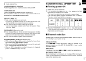
...], [P2], [P3], [Red], [ ] and [ ]). w Release [PTT] to return to turn power ON. Hold the microphone 5 to 10 cm (2 to 4 inches) from contacting you to call switch (assigned to voice transmission. Selective calling Non-selective calling 3 CONVENTIONAL OPERATION Receiving and transmitting NOTE: Transmitting without an antenna may be a selective calling system which allows you . q Select the desired TX code channel or 2/5-tone code according to your...
...], [P2], [P3], [Red], [ ] and [ ]). w Release [PTT] to return to turn power ON. Hold the microphone 5 to 10 cm (2 to 4 inches) from contacting you to call switch (assigned to voice transmission. Selective calling Non-selective calling 3 CONVENTIONAL OPERATION Receiving and transmitting NOTE: Transmitting without an antenna may be a selective calling system which allows you . q Select the desired TX code channel or 2/5-tone code according to your...

Instruction Manual
Page 12
... right automatically. u Push [Call] or [PTT] to enter the TX code edit mode. The channel is received. - FOR TX CODE CHANNEL TYPE: If the transceiver has a [TX Code CH Up] or [TX Code CH Down] key assignment, the programmed TX code channel can be toggled between the operating channel number (or name) and TX code channel number (or name). tion mode. • Select the desired channel using [ ]/[ ] if necessary. TO EDIT A TX...
... right automatically. u Push [Call] or [PTT] to enter the TX code edit mode. The channel is received. - FOR TX CODE CHANNEL TYPE: If the transceiver has a [TX Code CH Up] or [TX Code CH Down] key assignment, the programmed TX code channel can be toggled between the operating channel number (or name) and TX code channel number (or name). tion mode. • Select the desired channel using [ ]/[ ] if necessary. TO EDIT A TX...

Instruction Manual
Page 13
...] again to exit set mode at power ON and allows you can "customize" trans- 3 ceiver operation to select the item. Then push [ ] and [ ] to set seldom-changed settings. a DTMF channel appears. Please refer to select the desired DTMF channel. Up to transmit the DTMF code in the selected DTMF channel. e Push [DTMF Autodial] to 8 DTMF channels are available. The frequency inversion type is equipped...
...] again to exit set mode at power ON and allows you can "customize" trans- 3 ceiver operation to select the item. Then push [ ] and [ ] to set seldom-changed settings. a DTMF channel appears. Please refer to select the desired DTMF channel. Up to transmit the DTMF code in the selected DTMF channel. e Push [DTMF Autodial] to 8 DTMF channels are available. The frequency inversion type is equipped...

Instruction Manual
Page 14
... a 5-tone or MSK channel, respectively. [P1]; nel operation. [ ]/[ ]; mal voice level. • Transmit/Busy indicator lights red. CH Down/Up : While in the standby condition, selects the operating channel. lect], selects call list ID/transmit mes- spectively. [P2]/[Red]; Moni(Audi) : Push this key after the communication to select the call list or TX code channel, re- e Release [PTT] to return to each programmable switch as the default...
... a 5-tone or MSK channel, respectively. [P1]; nel operation. [ ]/[ ]; mal voice level. • Transmit/Busy indicator lights red. CH Down/Up : While in the standby condition, selects the operating channel. lect], selects call list ID/transmit mes- spectively. [P2]/[Red]; Moni(Audi) : Push this key after the communication to select the call list or TX code channel, re- e Release [PTT] to return to each programmable switch as the default...

Instruction Manual
Page 15
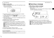
.... • The programmed text message (e.g." again to return to receive. • Transmit/Busy indicator lights green while receiving a signal. tion. mal voice level. 4 BIIS OPERATION D Group call q When a group call record - tion ID (or text) is displayed alternately, depending on the setting. • " " appears or blinks depending on the setting. 4 BIIS OPERATION D Displaying the received call is received; • Beeps sound. • " " appears and the mute is available...
.... • The programmed text message (e.g." again to return to receive. • Transmit/Busy indicator lights green while receiving a signal. tion. mal voice level. 4 BIIS OPERATION D Group call q When a group call record - tion ID (or text) is displayed alternately, depending on the setting. • " " appears or blinks depending on the setting. 4 BIIS OPERATION D Displaying the received call is received; • Beeps sound. • " " appears and the mute is available...

Instruction Manual
Page 16
... call code. However, an error beep sounds and " " is displayed when no answer back is received after the calls. to select the desired call code memory channel selection mode. However, an error beep sounds and " " is displayed when no answer back is received after the calls. D Using call capability is permitted. w Push [ ]/[ ] to enter queue memory channel selection mode. r Push [PTT] to send the "Clear down " signal. 4 BIIS OPERATION...
... call code. However, an error beep sounds and " " is displayed when no answer back is received after the calls. to select the desired call code memory channel selection mode. However, an error beep sounds and " " is displayed when no answer back is received after the calls. D Using call capability is permitted. w Push [ ]/[ ] to enter queue memory channel selection mode. r Push [PTT] to send the "Clear down " signal. 4 BIIS OPERATION...
Instruction Manual
Page 17
... is received, the transceiver re- t Repeat e and r to enter the TX code edit mode. • Editable code digit blinks. y Push [P0] (Call) or [PTT]* to the standby condition. NOTE: Only the calling station ID (or text) is displayed (no answer back is permitted. However, an error beep sounds and " " is displayed when no answer back is displayed 4 alternately, depending on the setting. 4 BIIS OPERATION D Direct code entry...
... is received, the transceiver re- t Repeat e and r to enter the TX code edit mode. • Editable code digit blinks. y Push [P0] (Call) or [PTT]* to the standby condition. NOTE: Only the calling station ID (or text) is displayed (no answer back is permitted. However, an error beep sounds and " " is displayed when no answer back is displayed 4 alternately, depending on the setting. 4 BIIS OPERATION D Direct code entry...
Instruction Manual
Page 20
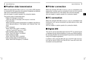
... operator for connection details. 4 PC connection When the optional OPC-966 INTERFACE CABLE is enabled. - In addition, when using a PC dispatch application. 4 BIIS OPERATION Position data transmission When the optional OPC-966 INTERFACE CABLE and a GPS receiver is connected to the transceiver, the position (longitude and latitude) data can be transmitted each time the PTT is pushed (log-in , the PTT side tone function can be used...
... operator for connection details. 4 PC connection When the optional OPC-966 INTERFACE CABLE is enabled. - In addition, when using a PC dispatch application. 4 BIIS OPERATION Position data transmission When the optional OPC-966 INTERFACE CABLE and a GPS receiver is connected to the transceiver, the position (longitude and latitude) data can be transmitted each time the PTT is pushed (log-in , the PTT side tone function can be used...

Instruction Manual
Page 21
... function is received/transmitted - BIIS indication 4 BIIS OPERATION The following operations is selected when transmitting a status call The Priority A channel is performed, the transceiver selects the Priority A channel automatically. Set the "Move to the transceiver. The emergency transmission is received, the transceiver switches to operate the transceiver again in this case. Enable the "Send Status on the emergency channel, however, when no change in the function display or beep emission...
... function is received/transmitted - BIIS indication 4 BIIS OPERATION The following operations is selected when transmitting a status call The Priority A channel is performed, the transceiver selects the Priority A channel automatically. Set the "Move to the transceiver. The emergency transmission is received, the transceiver switches to operate the transceiver again in this case. Enable the "Send Status on the emergency channel, however, when no change in the function display or beep emission...

Instruction Manual
Page 23
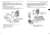
... lights green. AC adapter Supplied screws BC-152 37 38 D For your convenience 5 BATTERY CHARGING 5 Eyelet USE a rubber band to a flat surface, such as shown below. *Depending on the remaining power condition. 5 BATTERY CHARGING Optional battery chargers ï Regular charging with the BC-152 q Attach the BC-152 to secure the transceiver while charging, if desired. e Insert the battery pack with/without IC-F50/F60) is inserted. r Charge...
... lights green. AC adapter Supplied screws BC-152 37 38 D For your convenience 5 BATTERY CHARGING 5 Eyelet USE a rubber band to a flat surface, such as shown below. *Depending on the remaining power condition. 5 BATTERY CHARGING Optional battery chargers ï Regular charging with the BC-152 q Attach the BC-152 to secure the transceiver while charging, if desired. e Insert the battery pack with/without IC-F50/F60) is inserted. r Charge...
Instruction Manual
Page 25
... the DC power cable (OPC-656) IC-F50/F60 BP-227 5 AC adapter (Purchase separately.) AD-100 charger adapters are additionally required: • One AD-100 (purchase separately). • An AC adapter (may be used instead of optional Li-Ion battery packs. 5 BATTERY CHARGING D Rapid charging with the BC-119N+AD-100 The optional BC-119N provides rapid charging of the AC adapter. 5 BATTERY CHARGING D Rapid charging with some...
... the DC power cable (OPC-656) IC-F50/F60 BP-227 5 AC adapter (Purchase separately.) AD-100 charger adapters are additionally required: • One AD-100 (purchase separately). • An AC adapter (may be used instead of optional Li-Ion battery packs. 5 BATTERY CHARGING D Rapid charging with the BC-119N+AD-100 The optional BC-119N provides rapid charging of the AC adapter. 5 BATTERY CHARGING D Rapid charging with some...

