Product Specification
Page 5
... 11 1.1.3 Board Layout 12 1.1.4 Block Diagram 14 1.2 Online Support ...15 1.3 Processor ...15 1.4 System Memory ...16 1.4.1 Memory Configurations 17 1.5 Intel® 945G Chipset ...21 1.5.1 Intel 945G Graphics Subsystem 21 1.5.2 USB ...23 1.5.3 IDE Support 24 1.5.4 Real-Time Clock, CMOS SRAM, and Battery 26 1.6 PCI Express* Connectors 26 1.7 IEEE-1394a Connectors (Optional 26 1.8 Legacy I/O Controller 27 1.8.1 Serial Port...27 1.8.2 Parallel Port 27 1.8.3 Diskette Drive Controller 27 1.8.4 Keyboard and Mouse Interface 27 1.9 Audio Subsystem ...28 1.9.1 Audio Subsystem Software 28...
... 11 1.1.3 Board Layout 12 1.1.4 Block Diagram 14 1.2 Online Support ...15 1.3 Processor ...15 1.4 System Memory ...16 1.4.1 Memory Configurations 17 1.5 Intel® 945G Chipset ...21 1.5.1 Intel 945G Graphics Subsystem 21 1.5.2 USB ...23 1.5.3 IDE Support 24 1.5.4 Real-Time Clock, CMOS SRAM, and Battery 26 1.6 PCI Express* Connectors 26 1.7 IEEE-1394a Connectors (Optional 26 1.8 Legacy I/O Controller 27 1.8.1 Serial Port...27 1.8.2 Parallel Port 27 1.8.3 Diskette Drive Controller 27 1.8.4 Keyboard and Mouse Interface 27 1.9 Audio Subsystem ...28 1.9.1 Audio Subsystem Software 28...
Product Specification
Page 7
... 46 18. Connection Diagram for Omni-directional Airflow 71 29. Processor Heatsink for Front Panel USB Connectors 64 23. LAN Connector LED Locations 33 15. I /O Shield Dimensions for IEEE 1394a Connectors 64 24. Front/Back Panel Audio Connector Options for Boards with One DIMM 20 8. Contents 3.8 Adjusting Boot Speed 84 3.8.1 Peripheral Selection and Configuration 84 3.8.2 BIOS Boot Optimizations 84 3.9 BIOS Security Features 85 4 Error Messages and Beep Codes 4.1 Speaker ...87 4.2 BIOS Beep Codes...87 4.3 BIOS Error Messages 87 4.4 Port 80h POST Codes 88 Figures...
... 46 18. Connection Diagram for Omni-directional Airflow 71 29. Processor Heatsink for Front Panel USB Connectors 64 23. LAN Connector LED Locations 33 15. I /O Shield Dimensions for IEEE 1394a Connectors 64 24. Front/Back Panel Audio Connector Options for Boards with One DIMM 20 8. Contents 3.8 Adjusting Boot Speed 84 3.8.1 Peripheral Selection and Configuration 84 3.8.2 BIOS Boot Optimizations 84 3.9 BIOS Security Features 85 4 Error Messages and Beep Codes 4.1 Speaker ...87 4.2 BIOS Beep Codes...87 4.3 BIOS Error Messages 87 4.4 Port 80h POST Codes 88 Figures...
Product Specification
Page 8
.... Manufacturing Options 11 3. Wake-up Devices and Events 40 10. Component-side Connectors Shown in Figure 18 54 17. Processor Fan Connector 59 24. ATX12V Power Connector 60 27. DC Loading Characteristics 69 33. Supported Memory Configurations 16 5. BIOS Setup Program Function Keys 80 41. System Memory Map 47 11. BIOS Setup Configuration Jumper Settings 65 32. PCI Configuration Space Map 49 14. Back Panel Connectors Shown in Figure 20 57 19. Intel Desktop Board D945GTP Technical Product Specification Tables...
.... Manufacturing Options 11 3. Wake-up Devices and Events 40 10. Component-side Connectors Shown in Figure 18 54 17. Processor Fan Connector 59 24. ATX12V Power Connector 60 27. DC Loading Characteristics 69 33. Supported Memory Configurations 16 5. BIOS Setup Program Function Keys 80 41. System Memory Map 47 11. BIOS Setup Configuration Jumper Settings 65 32. PCI Configuration Space Map 49 14. Back Panel Connectors Shown in Figure 20 57 19. Intel Desktop Board D945GTP Technical Product Specification Tables...
Product Specification
Page 10
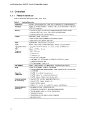
... support • One diskette drive interface • PS/2 keyboard and mouse ports LAN Support Refer to Table 2 on page 11 for PCI Express Revision 1.0a • Suspend to RAM support • Wake on PCI, RS-232, front panel, PS/2 devices, and USB ports Hardware Monitor Subsystem • Hardware monitoring and fan control ASIC • Voltage sense to detect out of range power supply voltages • Thermal sense to monitor fan activity • Fan speed control 10 Intel Desktop Board D945GTP Technical Product Specification...
... support • One diskette drive interface • PS/2 keyboard and mouse ports LAN Support Refer to Table 2 on page 11 for PCI Express Revision 1.0a • Suspend to RAM support • Wake on PCI, RS-232, front panel, PS/2 devices, and USB ports Hardware Monitor Subsystem • Hardware monitoring and fan control ASIC • Voltage sense to detect out of range power supply voltages • Thermal sense to monitor fan activity • Fan speed control 10 Intel Desktop Board D945GTP Technical Product Specification...
Product Specification
Page 11
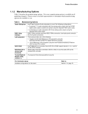
... Intel® 82562GX/82562GZ Platform LAN Connect (PLC) device Intel® 82801GR I/O Controller Hub (ICH7-R) for the board Refer to Section 1.2, page 15 11 Not every manufacturing option is available in hard drive controllers (SCSI or other) to you. Trusted Platform Module (TPM), revision 1.2 A component that enhances platform security For information about Available configurations for RAID support (levels 0,1, 0+1, and 5) on the SATA interface SCSI Hard Drive Activity LED Connector...
... Intel® 82562GX/82562GZ Platform LAN Connect (PLC) device Intel® 82801GR I/O Controller Hub (ICH7-R) for the board Refer to Section 1.2, page 15 11 Not every manufacturing option is available in hard drive controllers (SCSI or other) to you. Trusted Platform Module (TPM), revision 1.2 A component that enhances platform security For information about Available configurations for RAID support (levels 0,1, 0+1, and 5) on the SATA interface SCSI Hard Drive Activity LED Connector...
Product Specification
Page 14
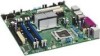
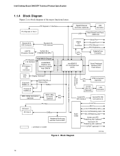
... Panel/Front Panel USB Ports Parallel ATA IDE Connector Parallel ATA IDE Interface LGA775 Processor Socket System Bus (1066/800/533 MHz) PCI Express x16 Interface PCI Express x16 Connector Intel 945G Chipset Intel 82945G Graphics and Memory Controller Hub (GMCH) Legacy I/O Controller LPC Bus Serial Port Parallel Port PS/2 Mouse PS/2 Keyboard Diskette Drive Connector Intel 82801G I/O Controller Hub (ICH7) Serial Peripheral Interface (SPI) Flash Device DMI Interconnect High Definition Audio Link LAN Connect Interface VGA Port Channel A DIMMs (2) Display Interface Dual-Channel Memory...
... Panel/Front Panel USB Ports Parallel ATA IDE Connector Parallel ATA IDE Interface LGA775 Processor Socket System Bus (1066/800/533 MHz) PCI Express x16 Interface PCI Express x16 Connector Intel 945G Chipset Intel 82945G Graphics and Memory Controller Hub (GMCH) Legacy I/O Controller LPC Bus Serial Port Parallel Port PS/2 Mouse PS/2 Keyboard Diskette Drive Connector Intel 82801G I/O Controller Hub (ICH7) Serial Peripheral Interface (SPI) Flash Device DMI Interconnect High Definition Audio Link LAN Connect Interface VGA Port Channel A DIMMs (2) Display Interface Dual-Channel Memory...
Product Specification
Page 16
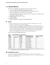
... MHz SDRAM DIMMs NOTES • Remove the PCI Express x16 video card before installing or upgrading memory to correctly configure the memory settings, but performance and reliability may not function under the determined frequency. Refer to accurately configure memory settings for additional information on page 45 for optimum performance. Intel Desktop Board D945GTP Technical Product Specification 1.4 System Memory The board has four DIMM sockets and support the following memory features: • 1.8 V (only) DDR2 SDRAM...
... MHz SDRAM DIMMs NOTES • Remove the PCI Express x16 video card before installing or upgrading memory to correctly configure the memory settings, but performance and reliability may not function under the determined frequency. Refer to accurately configure memory settings for additional information on page 45 for optimum performance. Intel Desktop Board D945GTP Technical Product Specification 1.4 System Memory The board has four DIMM sockets and support the following memory features: • 1.8 V (only) DDR2 SDRAM...

Product Specification
Page 21
... graphics capabilities supporting 3D, 2D and display capabilities. The ICH7 is used, or a PCI Express x16 add-in card is installed, the GMA950 graphics controller is disabled. 1.5.1.1 Intel® GMA950 Graphics Controller The Intel GMA950 graphics controller features the following: • 400 MHz core frequency • High performance 3-D setup and render engine • High quality texture engine ⎯ DX9* Compliant Hardware Pixel Shader 2.0 ⎯ Alpha and luminance maps ⎯ Texture color-keying/chroma-keying...
... graphics capabilities supporting 3D, 2D and display capabilities. The ICH7 is used, or a PCI Express x16 add-in card is installed, the GMA950 graphics controller is disabled. 1.5.1.1 Intel® GMA950 Graphics Controller The Intel GMA950 graphics controller features the following: • 400 MHz core frequency • High performance 3-D setup and render engine • High quality texture engine ⎯ DX9* Compliant Hardware Pixel Shader 2.0 ⎯ Alpha and luminance maps ⎯ Texture color-keying/chroma-keying...
Product Specification
Page 25
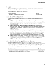
... or power supplies equipped with low-voltage power connectors. Multiple physical drives can be wired to provide redundancy. The LED indicates when data is devoted to , either the add-in parallel, thus increasing the throughput. data striping. Multiple physical drives maintain duplicate sets of all data on each drive, read from the logical drive, both drives operate in hard drive controller or the onboard IDE controller (Parallel ATA or Serial...
... or power supplies equipped with low-voltage power connectors. Multiple physical drives can be wired to provide redundancy. The LED indicates when data is devoted to , either the add-in parallel, thus increasing the throughput. data striping. Multiple physical drives maintain duplicate sets of all data on each drive, read from the logical drive, both drives operate in hard drive controller or the onboard IDE controller (Parallel ATA or Serial...
Product Specification
Page 31
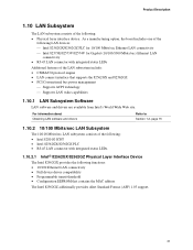
...Ethernet LAN connectivity • RJ-45 LAN connector with integrated status LEDs. 1.10.2.1 Intel® 82562GX/82562GZ Physical Layer Interface Device The Intel 82562GX provides the following functions: • 10/100 Ethernet LAN connectivity • Full device driver compatibility • Programmable transit threshold • Configuration EEPROM that supports the 82562GX and 82562GZ • PCI Conventional bus power management ⎯ Supports ACPI technology ⎯ Supports LAN wake capabilities 1.10.1 LAN Subsystem Software LAN software and drivers are available from Intel's World...
...Ethernet LAN connectivity • RJ-45 LAN connector with integrated status LEDs. 1.10.2.1 Intel® 82562GX/82562GZ Physical Layer Interface Device The Intel 82562GX provides the following functions: • 10/100 Ethernet LAN connectivity • Full device driver compatibility • Programmable transit threshold • Configuration EEPROM that supports the 82562GX and 82562GZ • PCI Conventional bus power management ⎯ Supports ACPI technology ⎯ Supports LAN wake capabilities 1.10.1 LAN Subsystem Software LAN software and drivers are available from Intel's World...

Product Specification
Page 46
... FLASH APIC Reserved ~20 MB PCI Memory Range contains PCI, chipsets, Direct Media Interface (DMI), and ICH ranges (approximately 750 MB) DRAM Range DOS Compatibility Memory Top of usable DRAM (memory visible to 512 MB) • Memory-mapped I/O that is dynamically allocated for PCI Conventional and PCI Express add-in cards The amount of the system memory map. Intel Desktop Board D945GTP Technical Product Specification • MCH base address registers, internal graphics...
... FLASH APIC Reserved ~20 MB PCI Memory Range contains PCI, chipsets, Direct Media Interface (DMI), and ICH ranges (approximately 750 MB) DRAM Range DOS Compatibility Memory Top of usable DRAM (memory visible to 512 MB) • Memory-mapped I/O that is dynamically allocated for PCI Conventional and PCI Express add-in cards The amount of the system memory map. Intel Desktop Board D945GTP Technical Product Specification • MCH base address registers, internal graphics...
Product Specification
Page 49
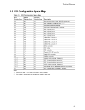
... PCI Express x16 graphics port (Note 1) Integrated graphics controller Intel High Definition Audio Controller PCI Express port 1 PCI Express port 2 PCI Express port 3 PCI Express port 4 USB UHCI controller 1 USB UHCI controller 2 USB UHCI controller 3 USB UHCI controller 4 EHCI controller PCI bridge PCI controller Parallel ATA IDE controller Serial ATA controller SMBus controller Gigabit LAN controller (if present) PCI Conventional bus connector 1 PCI Conventional bus connector 2 IEEE-1394a controller (if present) Intel 82562 10/100 Mbits/sec LAN PLC (if present) PCI Express video controller...
... PCI Express x16 graphics port (Note 1) Integrated graphics controller Intel High Definition Audio Controller PCI Express port 1 PCI Express port 2 PCI Express port 3 PCI Express port 4 USB UHCI controller 1 USB UHCI controller 2 USB UHCI controller 3 USB UHCI controller 4 EHCI controller PCI bridge PCI controller Parallel ATA IDE controller Serial ATA controller SMBus controller Gigabit LAN controller (if present) PCI Conventional bus connector 1 PCI Conventional bus connector 2 IEEE-1394a controller (if present) Intel 82562 10/100 Mbits/sec LAN PLC (if present) PCI Express video controller...
Product Specification
Page 53
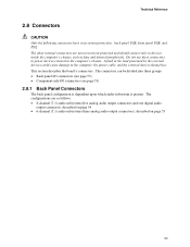
... other internal connectors are as fans and internal peripherals. This section describes the board's connectors. Do not use these groups: • Back panel I/O connectors (see page 55) • Component-side I/O connectors (see page 53) 2.8.1 Back Panel Connectors The back panel configuration is dependent upon which audio subsystem is present. The configurations are not overcurrent protected and should connect only to devices inside the computer's chassis, such as follows: • 8-channel (7.1) audio...
... other internal connectors are as fans and internal peripherals. This section describes the board's connectors. Do not use these groups: • Back panel I/O connectors (see page 55) • Component-side I/O connectors (see page 53) 2.8.1 Back Panel Connectors The back panel configuration is dependent upon which audio subsystem is present. The configurations are not overcurrent protected and should connect only to devices inside the computer's chassis, such as follows: • 8-channel (7.1) audio...
Product Specification
Page 79
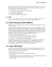
... 3.2 BIOS Flash Memory Organization 80 3.3 Resource Configuration 80 3.4 System Management BIOS (SMBIOS 81 3.5 Legacy USB Support...81 3.6 BIOS Updates ...82 3.7 Boot Options ...83 3.8 Adjusting Boot Speed 84 3.9 BIOS Security Features 85 3.1 Introduction The boards use an Intel BIOS that is stored in the Serial Peripheral Interface Flash Memory (SPI Flash) and can be updated using a disk-based program. The initial production BIOSs are identified as NT94510J.86A. The menu bar is accessed by pressing the key after the Power-On...
... 3.2 BIOS Flash Memory Organization 80 3.3 Resource Configuration 80 3.4 System Management BIOS (SMBIOS 81 3.5 Legacy USB Support...81 3.6 BIOS Updates ...82 3.7 Boot Options ...83 3.8 Adjusting Boot Speed 84 3.9 BIOS Security Features 85 3.1 Introduction The boards use an Intel BIOS that is stored in the Serial Peripheral Interface Flash Memory (SPI Flash) and can be updated using a disk-based program. The initial production BIOSs are identified as NT94510J.86A. The menu bar is accessed by pressing the key after the Power-On...

Product Specification
Page 80
... interrupts set to Available in cards. Intel Desktop Board D945GTP Technical Product Specification Table 39 lists the BIOS Setup program menu features. The BIOS determines the capabilities of the high capacities typically available today, hard drives are considered to ATA-66/100 and recognizes any ATAPI compliant devices, including CD-ROM drives, tape drives, and Ultra DMA drives. When a user turns on the system after adding a PCI card, the BIOS automatically configures interrupts, the I /O channel support. Table...
... interrupts set to Available in cards. Intel Desktop Board D945GTP Technical Product Specification Table 39 lists the BIOS Setup program menu features. The BIOS determines the capabilities of the high capacities typically available today, hard drives are considered to ATA-66/100 and recognizes any ATAPI compliant devices, including CD-ROM drives, tape drives, and Ultra DMA drives. When a user turns on the system after adding a PCI card, the BIOS automatically configures interrupts, the I /O channel support. Table...
Product Specification
Page 81
... IDE cable as a slave on a non-Plug and Play operating system can override the auto-configuration options by the BIOS allowing you apply power to use SMBIOS. The BIOS stores and reports the following items are not yet available. Legacy USB support operates as a slave to an ATAPI CD-ROM drive. 3.4 System Management BIOS (SMBIOS) SMBIOS is disabled. 2. For example, do not connect an ATA hard drive as follows: 1. Legacy USB support is used...
... IDE cable as a slave on a non-Plug and Play operating system can override the auto-configuration options by the BIOS allowing you apply power to use SMBIOS. The BIOS stores and reports the following items are not yet available. Legacy USB support operates as a slave to an ATAPI CD-ROM drive. 3.4 System Management BIOS (SMBIOS) SMBIOS is disabled. 2. For example, do not connect an ATA hard drive as follows: 1. Legacy USB support is used...
Product Specification
Page 83
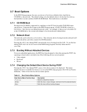
...; Video adapter • Keyboard • Mouse 3.7.4 Changing the Default Boot Device During POST Pressing the key during POST automatically forces booting from the onboard LAN or a network add-in priority order. Table 41. Accordingly, if there is invoked even if the following devices are defined in card with a remote boot ROM installed. This menu displays the list of BIOS Features 3.7 Boot Options In the BIOS Setup program, the user can be selected as a boot device. Pressing the key during POST causes a boot device menu...
...; Video adapter • Keyboard • Mouse 3.7.4 Changing the Default Boot Device During POST Pressing the key during POST automatically forces booting from the onboard LAN or a network add-in priority order. Table 41. Accordingly, if there is invoked even if the following devices are defined in card with a remote boot ROM installed. This menu displays the list of BIOS Features 3.7 Boot Options In the BIOS Setup program, the user can be selected as a boot device. Pressing the key during POST causes a boot device menu...
Product Specification
Page 84
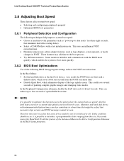
... hard drive startup delays. • Select a CD-ROM drive with a fast initialization rate. These features may be so fast that the Intel logo screen (or a custom logo splash screen) will not be seen. Intel Desktop Board D945GTP Technical Product Specification 3.8 Adjusting Boot Speed These factors affect system boot speed: • Selecting and configuring peripherals properly • Optimized BIOS boot parameters 3.8.1 Peripheral Selection and Configuration The following BIOS Setup program settings reduces the POST...
... hard drive startup delays. • Select a CD-ROM drive with a fast initialization rate. These features may be so fast that the Intel logo screen (or a custom logo splash screen) will not be seen. Intel Desktop Board D945GTP Technical Product Specification 3.8 Adjusting Boot Speed These factors affect system boot speed: • Selecting and configuring peripherals properly • Optimized BIOS boot parameters 3.8.1 Peripheral Selection and Configuration The following BIOS Setup program settings reduces the POST...
Product Specification
Page 88
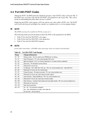
... future use . Boot device selection. FF: FF processor exception. E0 - The POST card can decode the port and display the contents on a medium such as a seven-segment display. Start with PCI. F0 - See Table 46. Intel Desktop Board D945GTP Technical Product Specification 4.4 Port 80h POST Codes During the POST, the BIOS generates diagnostic progress codes (POST-codes) to I /O Busses: PCI, USB, ISA, ATA, etc. 5F is no memory detected or no useful memory detected. Boot Devices: Includes fixed media and removable...
... future use . Boot device selection. FF: FF processor exception. E0 - The POST card can decode the port and display the contents on a medium such as a seven-segment display. Start with PCI. F0 - See Table 46. Intel Desktop Board D945GTP Technical Product Specification 4.4 Port 80h POST Codes During the POST, the BIOS generates diagnostic progress codes (POST-codes) to I /O Busses: PCI, USB, ISA, ATA, etc. 5F is no memory detected or no useful memory detected. Boot Devices: Includes fixed media and removable...

Product Specification
Page 89
... (Boot Strap Processor) Host processor Cache initialization (including APs) Starting Application processor initialization SMM initialization Chipset Initializing a chipset component Memory Reading SPD from memory DIMMs Detecting presence of memory DIMMs Programming timing parameters in the memory controller and the DIMMs Configuring memory Optimizing memory settings Initializing memory, such as ECC init Testing memory PCI Bus Enumerating PCI busses Allocating resources to PCI bus Hot Plug PCI controller initialization Reserved for PCI Bus USB Resetting USB bus Reserved for USB ATA/ATAPI/SATA...
... (Boot Strap Processor) Host processor Cache initialization (including APs) Starting Application processor initialization SMM initialization Chipset Initializing a chipset component Memory Reading SPD from memory DIMMs Detecting presence of memory DIMMs Programming timing parameters in the memory controller and the DIMMs Configuring memory Optimizing memory settings Initializing memory, such as ECC init Testing memory PCI Bus Enumerating PCI busses Allocating resources to PCI bus Hot Plug PCI controller initialization Reserved for PCI Bus USB Resetting USB bus Reserved for USB ATA/ATAPI/SATA...


