Product Guide
Page 3
...Connector and Component Locations 8 Back Panel Connectors 9 Processor ...10 Memory ...10 PCI Riser Slots ...10 Video ...11 SCSI Controller ...11 ATA-100 Controller...11 IDE RAID...11 Network Controller...12 Network Teaming Features 12 Keyboard and Mouse ...14 RJ-45 Serial Port ...14 ACPI...16 Security ...17 Intrusion Switch Monitoring 17 Software Locks ...17 2 Installation Procedures Install the I/O Shield ...21 Rearrange the Standoffs ...22 Server Board Bumpers ...23 Install the Server Board ...24 Installing Processors ...25 Install the Processor Terminator 28 Memory ...29 Connect Cables...
...Connector and Component Locations 8 Back Panel Connectors 9 Processor ...10 Memory ...10 PCI Riser Slots ...10 Video ...11 SCSI Controller ...11 ATA-100 Controller...11 IDE RAID...11 Network Controller...12 Network Teaming Features 12 Keyboard and Mouse ...14 RJ-45 Serial Port ...14 ACPI...16 Security ...17 Intrusion Switch Monitoring 17 Software Locks ...17 2 Installation Procedures Install the I/O Shield ...21 Rearrange the Standoffs ...22 Server Board Bumpers ...23 Install the Server Board ...24 Installing Processors ...25 Install the Processor Terminator 28 Memory ...29 Connect Cables...
Product Guide
Page 4
Power-On Self-Test (POST 43 Using BIOS Setup ...43 Record BIOS Setup Settings 44 If BIOS Setup Is Inaccessible 44 BIOS Setup Menus...44 Main Menu...45 Advanced Menu...46 Security Menu...49 Server Menu ...50 Boot Menu ...52 Exit Menu ...53 Temporarily Changing the Boot Device Priority 53 Permanently Changing the Boot Device Priority 54 Running the Adaptec SCSISelect Utility 54 When to Run the Adaptec SCSISelect Utility 54 Running the SCSISelect Utility 54 Configuring the Adaptec AIC-7899...
Power-On Self-Test (POST 43 Using BIOS Setup ...43 Record BIOS Setup Settings 44 If BIOS Setup Is Inaccessible 44 BIOS Setup Menus...44 Main Menu...45 Advanced Menu...46 Security Menu...49 Server Menu ...50 Boot Menu ...52 Exit Menu ...53 Temporarily Changing the Boot Device Priority 53 Permanently Changing the Boot Device Priority 54 Running the Adaptec SCSISelect Utility 54 When to Run the Adaptec SCSISelect Utility 54 Running the SCSISelect Utility 54 Configuring the Adaptec AIC-7899...
Product Guide
Page 6
... 10. Installing Processors...25 11. Connecting Cables ...30 17. Installing the Heat Sink 35 20. BMC LAN-Configuration Dialog 68 28. Jumper Locations ...91 Tables 1. Software Security Features 18 5. Server Board Features 7 3. Connect the Heat Sink Fan 36 22. Rear COM2 Port Adapter Pin-out 15 4. Rearrange the Standoffs 22 7. BIOS Setup Menu Display 45 9. Power Usage Worksheet 1 102 13. Platform Event Paging Dialog 67 27. Installing the I/O Shield 21 6. Installing Memory ...29...
... 10. Installing Processors...25 11. Connecting Cables ...30 17. Installing the Heat Sink 35 20. BMC LAN-Configuration Dialog 68 28. Jumper Locations ...91 Tables 1. Software Security Features 18 5. Server Board Features 7 3. Connect the Heat Sink Fan 36 22. Rear COM2 Port Adapter Pin-out 15 4. Rearrange the Standoffs 22 7. BIOS Setup Menu Display 45 9. Power Usage Worksheet 1 102 13. Platform Event Paging Dialog 67 27. Installing the I/O Shield 21 6. Installing Memory ...29...
Product Guide
Page 8
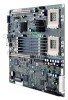
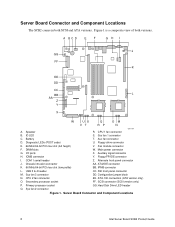
... fan 1 connector C. Aux fan connector D. Main power connector G. ICMB connector Y. Chassis intrusion connector AA. Configuration jumper block N. SCSI connector (SCSI version only) P. Server Board Connector and Component Locations 8 Intel Server Board SCB2 Product Guide Figure 1 is a composite view of both SCSI and ATA versions. DIMM slots W. Alternate front panel connector J. ATA/IDE connector K. 66 MHz/64-bit PCI riser slot (low profile) BB. CPU 2 fan connector EE. Primary processor socket GG. ID LED S. Floppy drive connector E. 66 MHz/64-bit PCI...
... fan 1 connector C. Aux fan connector D. Main power connector G. ICMB connector Y. Chassis intrusion connector AA. Configuration jumper block N. SCSI connector (SCSI version only) P. Server Board Connector and Component Locations 8 Intel Server Board SCB2 Product Guide Figure 1 is a composite view of both SCSI and ATA versions. DIMM slots W. Alternate front panel connector J. ATA/IDE connector K. 66 MHz/64-bit PCI riser slot (low profile) BB. CPU 2 fan connector EE. Primary processor socket GG. ID LED S. Floppy drive connector E. 66 MHz/64-bit PCI...

Product Guide
Page 11
... 3D • CRT and LCD monitors up to four drives are required Description 11 The SCSI bus is installed in and need to 100 Hz vertical refresh rate The server board supports disabling of the onboard video through a jumper or resistor pack on the server board with PCI Local Bus Specification Revision 2.2 IDE RAID The ATA-100 controller supports IDE RAID through the use of disks. LVD devices generally do not have termination...
... 3D • CRT and LCD monitors up to four drives are required Description 11 The SCSI bus is installed in and need to 100 Hz vertical refresh rate The server board supports disabling of the onboard video through a jumper or resistor pack on the server board with PCI Local Bus Specification Revision 2.2 IDE RAID The ATA-100 controller supports IDE RAID through the use of disks. LVD devices generally do not have termination...

Product Guide
Page 18
... not be powered off when secure mode is in drive A, the system prompts for the inactivity time-out period. • Must enter the supervisor password if you must enter the user password to use the Setup main menu, Floppy Options, and specify Floppy Access as read only. Secure Mode Configure and enable the secure boot mode by pressing the key combination. Summary of system power. In general, to enable or set a hot-key combination (through Setup), you...
... not be powered off when secure mode is in drive A, the system prompts for the inactivity time-out period. • Must enter the supervisor password if you must enter the user password to use the Setup main menu, Floppy Options, and specify Floppy Access as read only. Secure Mode Configure and enable the secure boot mode by pressing the key combination. Summary of system power. In general, to enable or set a hot-key combination (through Setup), you...
Product Guide
Page 42
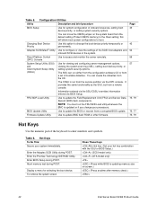
... a corrupted BIOS update. FRU/SDR Load Utility Use to update BMC flash ROM or other firmware. Enter BIOS Setup during POST. Display a menu for viewing and configuring server management options, viewing the system event log (SEL), setting boot device priority, or setting system security options. To remove the splash screen. BIOS Update Utility Use to boot. Changing Boot Device Priority Adaptec SCSISelect† Utility Use this will allow most system configurations to update the BIOS or recover from a remote console. Enter the Promise Technology IDE RAID Utility...
... a corrupted BIOS update. FRU/SDR Load Utility Use to update BMC flash ROM or other firmware. Enter BIOS Setup during POST. Display a menu for viewing and configuring server management options, viewing the system event log (SEL), setting boot device priority, or setting system security options. To remove the splash screen. BIOS Update Utility Use to boot. Changing Boot Device Priority Adaptec SCSISelect† Utility Use this will allow most system configurations to update the BIOS or recover from a remote console. Enter the Promise Technology IDE RAID Utility...

Product Guide
Page 46
... at power up. 46 Intel Server Board SCB2 Product Guide Reports the speed of processor(s) installed in the system. This feature does not appear if processor 1 is absent or disabled. System automatically resets to clear the system configuration data during next boot. If enabled, the system records the serial number of each processor. Enables or disables the "Numlock" function at POST. Reports Stepping for Processor 2. Advanced Menu Feature PCI Configuration Peripheral Configuration Memory Configuration Advanced Chipset Control Reset Configuration Data Plug...
... at power up. 46 Intel Server Board SCB2 Product Guide Reports the speed of processor(s) installed in the system. This feature does not appear if processor 1 is absent or disabled. System automatically resets to clear the system configuration data during next boot. If enabled, the system records the serial number of each processor. Enables or disables the "Numlock" function at POST. Reports Stepping for Processor 2. Advanced Menu Feature PCI Configuration Peripheral Configuration Memory Configuration Advanced Chipset Control Reset Configuration Data Plug...

Product Guide
Page 47
... Feature USB Function Onboard NIC 1 Onboard NIC 2 Onboard SCSI Onboard R-IDE Onboard Video Riser Card Override Choices Press Press Press Press Press Press Enabled Disabled Description Enters Submenu Enters Submenu Enters Submenu Enters Submenu (SCSI model only) Enters Submenu (ATA model only) Enters Submenu This option will only be displayed USB Function Submenu Feature USB Function Choices Enabled Disabled Description Enables the embedded USB controller. In a 2U chassis, options for additional PCI slots PCI bus B will be displayed Used to enable or disable an option ROM that...
... Feature USB Function Onboard NIC 1 Onboard NIC 2 Onboard SCSI Onboard R-IDE Onboard Video Riser Card Override Choices Press Press Press Press Press Press Enabled Disabled Description Enters Submenu Enters Submenu Enters Submenu Enters Submenu (SCSI model only) Enters Submenu (ATA model only) Enters Submenu This option will only be displayed USB Function Submenu Feature USB Function Choices Enabled Disabled Description Enables the embedded USB controller. In a 2U chassis, options for additional PCI slots PCI bus B will be displayed Used to enable or disable an option ROM that...

Product Guide
Page 48
... Port 1 IRQ Serial Port 2 Address Serial Port 2 IRQ Diskette Controller Legacy USB Support Front Panel USB Choices Disabled 3F8 2F8 3E8 2E8 4 3 Disabled 3F8 2F8 3E8 2E8 4 3 Enabled Disabled Disabled Keyboard Only Auto Keyboard & Mouse Disabled Enabled Description Used to enable the USB ports accessed through the internal USB header found on the next system boot. 48 Intel Server Board SCB2 Product Guide If console redirection is used to display whether DIMMs are present in bank #3 If enabled, BIOS will be automatically reset to values configured in bank #1 Informational screen...
... Port 1 IRQ Serial Port 2 Address Serial Port 2 IRQ Diskette Controller Legacy USB Support Front Panel USB Choices Disabled 3F8 2F8 3E8 2E8 4 3 Disabled 3F8 2F8 3E8 2E8 4 3 Enabled Disabled Disabled Keyboard Only Auto Keyboard & Mouse Disabled Enabled Description Used to enable the USB ports accessed through the internal USB header found on the next system boot. 48 Intel Server Board SCB2 Product Guide If console redirection is used to display whether DIMMs are present in bank #3 If enabled, BIOS will be automatically reset to values configured in bank #1 Informational screen...

Product Guide
Page 49
... boots in secure mode. This option only appears on the screen after a "user" password has been entered. Sets the User access level for entering BIOS Setup. Once set and enabled, the system prompts you for secure mode to activate. This option only appears on the screen after a "user" password has been entered. When the key is pressed, a password prompt appears. Advanced Chipset Control Submenu Feature Wake on Ring Wake on LAN Wake on PME Wake on RTC Alarm Option Disabled Enabled Disabled Enabled Disabled Enabled Disabled Enabled Description Legacy wake only...
... boots in secure mode. This option only appears on the screen after a "user" password has been entered. Sets the User access level for entering BIOS Setup. Once set and enabled, the system prompts you for secure mode to activate. This option only appears on the screen after a "user" password has been entered. When the key is pressed, a password prompt appears. Advanced Chipset Control Submenu Feature Wake on Ring Wake on LAN Wake on PME Wake on RTC Alarm Option Disabled Enabled Disabled Enabled Disabled Enabled Disabled Enabled Description Legacy wake only...

Product Guide
Page 53
... next boot process. 1. When POST completes, a popup Boot menu displays. 3. At any ATAPI CDROM Drive installed Exit Menu You can change the boot device priority for the current boot process. Select an option using the up or down arrow keys. Pressing does not exit this menu. BIOS Setup utility is "Enter Setup." Saves new BIOS settings and stores them as custom default values. Discards any changes made to select a device. ATAPI CDROM Drives Submenu For options on this menu, use...
... next boot process. 1. When POST completes, a popup Boot menu displays. 3. At any ATAPI CDROM Drive installed Exit Menu You can change the boot device priority for the current boot process. Select an option using the up or down arrow keys. Pressing does not exit this menu. BIOS Setup utility is "Enter Setup." Saves new BIOS settings and stores them as custom default values. Discards any changes made to select a device. ATAPI CDROM Drives Submenu For options on this menu, use...
Product Guide
Page 58
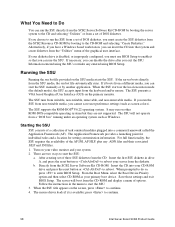
... to enter BIOS Setup. Follow the instructions in the local execution mode (the default mode), the SSU accepts input from the CD-ROM and display a menu of task oriented modules plugged into your system. 2. When the SSU title appears on other ROM-DOS-compatible operating systems but they are two ways to reboot. Turn on your video monitor and your CD-ROM drive and press the reset button or to start...
... to enter BIOS Setup. Follow the instructions in the local execution mode (the default mode), the SSU accepts input from the CD-ROM and display a menu of task oriented modules plugged into your system. 2. When the SSU title appears on other ROM-DOS-compatible operating systems but they are two ways to reboot. Turn on your video monitor and your CD-ROM drive and press the reset button or to start...
Product Guide
Page 61
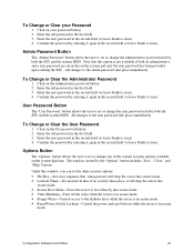
... BIOS. Configuration Software and Utilities 61 To Change or Clear your password button. 2. All changes to the user password take place immediately. Enter the new password in the second field (or leave blank to clear). 4. User Password Button The 'User Password' button allows the user to set or change the user password used by entering it will drop the server into secure mode. • Secure Boot Mode-Force the server to the diskette drive while the server is in secure mode. • Reset/Power Switch...
... BIOS. Configuration Software and Utilities 61 To Change or Clear your password button. 2. All changes to the user password take place immediately. Enter the new password in the second field (or leave blank to clear). 4. User Password Button The 'User Password' button allows the user to set or change the user password used by entering it will drop the server into secure mode. • Secure Boot Mode-Force the server to the diskette drive while the server is in secure mode. • Reset/Power Switch...

Product Guide
Page 79
... Field Replacement Unit (FRU) and Sensor Data Record (SDR) load utility is a DOS-based program used to update the BMCs firmware code. Press "N" to continue unless otherwise directed by the release notes or an Intel support professional. 8. Insert the diskette into the drive and boot to it should upload boot code. If the diskette drive is disabled, or improperly configured, use BIOS Setup to enable it later. 3. Firmware Update Utility Description The Firmware Update Utility is...
... Field Replacement Unit (FRU) and Sensor Data Record (SDR) load utility is a DOS-based program used to update the BMCs firmware code. Press "N" to continue unless otherwise directed by the release notes or an Intel support professional. 8. Insert the diskette into the drive and boot to it should upload boot code. If the diskette drive is disabled, or improperly configured, use BIOS Setup to enable it later. 3. Firmware Update Utility Description The Firmware Update Utility is...
Product Guide
Page 88
... port is set to "Disabled." Diskette Drive Activity Light Does Not Light Check the following : q Are the power and signal cables to the connector at the system back panel. 88 Intel Server Board SCB2 Product Guide q Is the diskette drive activity light always on the drive set correctly? If you will need a crossover cable (see your service representative or authorized dealer for the same duplex mode as the network controller. q Is the onboard IDE controller enabled...
... port is set to "Disabled." Diskette Drive Activity Light Does Not Light Check the following : q Are the power and signal cables to the connector at the system back panel. 88 Intel Server Board SCB2 Product Guide q Is the diskette drive activity light always on the drive set correctly? If you will need a crossover cable (see your service representative or authorized dealer for the same duplex mode as the network controller. q Is the onboard IDE controller enabled...

Product Guide
Page 93
... motherboard devices. Display splash logo. 37h Off G A A Display Sign on message next. 37h Off G A A Initialize language module. Displaying the power-on message, BIOS ID and processor information. 38h G Off R R Detect USB Mouse: Initializing the bus input, and general devices next, if present. 34h Off G R R Reset IDE Controllers continued Technical Reference 93 Restore from backup if corrupted. 12h Off Off G R Load defaults in CMOS RAM if bad checksum or CMOS clear jumper...
... motherboard devices. Display splash logo. 37h Off G A A Display Sign on message next. 37h Off G A A Initialize language module. Displaying the power-on message, BIOS ID and processor information. 38h G Off R R Detect USB Mouse: Initializing the bus input, and general devices next, if present. 34h Off G R R Reset IDE Controllers continued Technical Reference 93 Restore from backup if corrupted. 12h Off Off G R Load defaults in CMOS RAM if bad checksum or CMOS clear jumper...
Product Guide
Page 105
... password, 19 Configuration, 92, 93 Configuration Save/Restore Add-In, 65 configuration utilities. See utilities configuring server board jumpers location on server board, 91 configuring system BIOS Setup, 42 System Setup Utility, 42 controller, 92, 94 keyboard/mouse, 14 network, 7 SCSI, 11 video, 7, 11 D diagnostics, preparing system for testing, 85 Direct Platform Control, 56 modes of safely, 39 installing, 40 removing, 39 BIOS, 61, 92, 93, 94 changing the language, 78 recovering, 78 update utility, 42 upgrading, 77 BIOS ID, 93 BIOS Setup Boot Device...
... password, 19 Configuration, 92, 93 Configuration Save/Restore Add-In, 65 configuration utilities. See utilities configuring server board jumpers location on server board, 91 configuring system BIOS Setup, 42 System Setup Utility, 42 controller, 92, 94 keyboard/mouse, 14 network, 7 SCSI, 11 video, 7, 11 D diagnostics, preparing system for testing, 85 Direct Platform Control, 56 modes of safely, 39 installing, 40 removing, 39 BIOS, 61, 92, 93, 94 changing the language, 78 recovering, 78 update utility, 42 upgrading, 77 BIOS ID, 93 BIOS Setup Boot Device...

Product Guide
Page 106
... FRUSDR load utility, 42 FRUSDR Load Utility, 79 H Hard Drive submenu, configuring, BIOS Setup, 52 heat sink, fan, 34, 37, 38 hot key option, quick reference, 42 I-K I/O PCI expansion slots, 7 ports provided, 7 Initialization, 92, 93 Integrated Peripheral submenu, configuring in BIOS Setup, 48 intrusion detection, 17 jumpers, do not damage when changing, 32 keyboard compatibility, 14 lockout timer, seting in SCU, 14 L LCD, 93 lithium backup battery disposing of safely, 39 installing, 40 removing, 39 M memory capacity...
... FRUSDR load utility, 42 FRUSDR Load Utility, 79 H Hard Drive submenu, configuring, BIOS Setup, 52 heat sink, fan, 34, 37, 38 hot key option, quick reference, 42 I-K I/O PCI expansion slots, 7 ports provided, 7 Initialization, 92, 93 Integrated Peripheral submenu, configuring in BIOS Setup, 48 intrusion detection, 17 jumpers, do not damage when changing, 32 keyboard compatibility, 14 lockout timer, seting in SCU, 14 L LCD, 93 lithium backup battery disposing of safely, 39 installing, 40 removing, 39 M memory capacity...

Product Guide
Page 107
... startup, 83 network, 89 no booting from diskette without password, 18 using hot keys to enter, 42 security, 17, 18 alarm switches, 17 boot sequence, 19 enabling/disabling floppy writes, 18 locking mouse, keyboard with timer, 14, 19 password, 19 secure mode, 18 secure mode, setting in SCU, 18 software lock, SCU, 17 unattended start, 19 using hot key combination, 42 video blanking, 19 Security Add-in, 60 Security menu, configuring in BIOS Setup, 49...
... startup, 83 network, 89 no booting from diskette without password, 18 using hot keys to enter, 42 security, 17, 18 alarm switches, 17 boot sequence, 19 enabling/disabling floppy writes, 18 locking mouse, keyboard with timer, 14, 19 password, 19 secure mode, 18 secure mode, setting in SCU, 18 software lock, SCU, 17 unattended start, 19 using hot key combination, 42 video blanking, 19 Security Add-in, 60 Security menu, configuring in BIOS Setup, 49...


