Ventilation Pairing Chart
Page 1
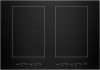
...motors: UXB1200DYS, UXB0600DYS or UXI1200DYS. Refer to installation instructions packaged with any cutouts based on this information. VENTIL ATION AND GAS COOK TOP PAIRINGS GAS COOKTOPS MODELS 60,000 BTU TOTAL OR MORE 36" 30...■ - ■ ■ ■ ■ ■ ■ ■ ■ - ■ ■ - ■ ■ *Custom hood liners can be used with product before selecting cabinetry, making cutouts or beginning installation. Not Recommended IMPORTANT: Dimensional specifications are appropriately UL, CUL or CSA approved. KEY ■ Recommended -
...motors: UXB1200DYS, UXB0600DYS or UXI1200DYS. Refer to installation instructions packaged with any cutouts based on this information. VENTIL ATION AND GAS COOK TOP PAIRINGS GAS COOKTOPS MODELS 60,000 BTU TOTAL OR MORE 36" 30...■ - ■ ■ ■ ■ ■ ■ ■ ■ - ■ ■ - ■ ■ *Custom hood liners can be used with product before selecting cabinetry, making cutouts or beginning installation. Not Recommended IMPORTANT: Dimensional specifications are appropriately UL, CUL or CSA approved. KEY ■ Recommended -

Ventilation Pairing Chart
Page 2
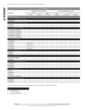
... CUSTOM HOOD LINERS* UXL5430BSS - - JXW8536HS ■ ■ JXW8936DS ■ ■ WALL-MOUNT HOODS JVR0430H - - Not Recommended 24" JIC4724H ■ - ■ ■ ■ ■ ■ ■ ■ ■ ■ ■ IMPORTANT: Dimensional specifications are... to installation instructions packaged with any cutouts based on this information. VENTIL ATION AND INDUCTION COOK TOP PAIRINGS MODELS INDUCTION 36" JIC4536X JIC4736H VENTILATION STYLE ACCOLADE® DOWNDRAFT SYSTEM JXD7836BS ■ ■ TELESCOPING DOWNDRAFT SYSTEMS ...
... CUSTOM HOOD LINERS* UXL5430BSS - - JXW8536HS ■ ■ JXW8936DS ■ ■ WALL-MOUNT HOODS JVR0430H - - Not Recommended 24" JIC4724H ■ - ■ ■ ■ ■ ■ ■ ■ ■ ■ ■ IMPORTANT: Dimensional specifications are... to installation instructions packaged with any cutouts based on this information. VENTIL ATION AND INDUCTION COOK TOP PAIRINGS MODELS INDUCTION 36" JIC4536X JIC4736H VENTILATION STYLE ACCOLADE® DOWNDRAFT SYSTEM JXD7836BS ■ ■ TELESCOPING DOWNDRAFT SYSTEMS ...

Ventilation Pairing Chart
Page 3
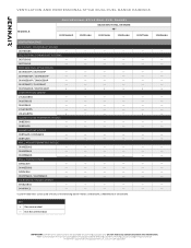
...; ■ JXI8936DS ■ ■ ■ ISLAND-MOUNT HOODS JXI8736DS / JXI8536DS ■ ■ ■ JXI8742DS ■ ■ ■ WALL-MOUNT PERIMETRIC HOODS JXW8530HS - - - JXW8536HS ■ ■ ■ JXW8936DS ■ ■ ■ WALL-MOUNT HOODS JVR0430H - - - JMV9196CS - - - *Custom hood liners can be used with product before selecting cabinetry, making cutouts or beginning installation. VENTIL ATION AND RADIANT COOK TOP PAIRINGS MODELS RADIANT JEC4536H 36" JEC3536B JEC3536H VENTILATION STYLE ACCOLADE...
...; ■ JXI8936DS ■ ■ ■ ISLAND-MOUNT HOODS JXI8736DS / JXI8536DS ■ ■ ■ JXI8742DS ■ ■ ■ WALL-MOUNT PERIMETRIC HOODS JXW8530HS - - - JXW8536HS ■ ■ ■ JXW8936DS ■ ■ ■ WALL-MOUNT HOODS JVR0430H - - - JMV9196CS - - - *Custom hood liners can be used with product before selecting cabinetry, making cutouts or beginning installation. VENTIL ATION AND RADIANT COOK TOP PAIRINGS MODELS RADIANT JEC4536H 36" JEC3536B JEC3536H VENTILATION STYLE ACCOLADE...

Ventilation Pairing Chart
Page 4
... the following blower motors: UXB1200DYS, UXB0600DYS or UXI1200DYS. Refer to installation instructions packaged with any cutouts based on this information. KEY ■ Recommended - All JennAir® appliances are provided for planning purposes only. VENTIL ATION AND RADIANT COOK TOP PAIRINGS MODELS JEC4430B RADIANT 30" JEC4430H JEC3430B JEC3430H VENTILATION STYLE ACCOLADE® DOWNDRAFT SYSTEM JXD7836BS ■ ■ ■ ■ TELESCOPING...
... the following blower motors: UXB1200DYS, UXB0600DYS or UXI1200DYS. Refer to installation instructions packaged with any cutouts based on this information. KEY ■ Recommended - All JennAir® appliances are provided for planning purposes only. VENTIL ATION AND RADIANT COOK TOP PAIRINGS MODELS JEC4430B RADIANT 30" JEC4430H JEC3430B JEC3430H VENTILATION STYLE ACCOLADE® DOWNDRAFT SYSTEM JXD7836BS ■ ■ ■ ■ TELESCOPING...
Ventilation Pairing Chart
Page 8
... / HOOD COMBOS JMV8208CS - - - - WALL-MOUNT HOODS JVR0430H - - - - JXW8736DS / JXW8536DS - - - - JDRP748H - - - - - - - ■ - - - - ■ - - - - - - - - - - - - - JXW9048WP / JXW9048HP ■ ■ ■ ■ CUSTOM HOOD LINERS* UXL5430BSS - - - - ISLAND-MOUNT PERIMETRIC HOODS JXI8536HS - - - - V EN T IL AT I O N A ND PR O FE S S I O N A L-S T Y LE D UA L- KEY ■ Recommended - WALL-MOUNT PERIMETRIC HOODS JXW8530HS - - - - JXW8536HS - - - - Refer to installation instructions packaged with any cutouts based on...
... / HOOD COMBOS JMV8208CS - - - - WALL-MOUNT HOODS JVR0430H - - - - JXW8736DS / JXW8536DS - - - - JDRP748H - - - - - - - ■ - - - - ■ - - - - - - - - - - - - - JXW9048WP / JXW9048HP ■ ■ ■ ■ CUSTOM HOOD LINERS* UXL5430BSS - - - - ISLAND-MOUNT PERIMETRIC HOODS JXI8536HS - - - - V EN T IL AT I O N A ND PR O FE S S I O N A L-S T Y LE D UA L- KEY ■ Recommended - WALL-MOUNT PERIMETRIC HOODS JXW8530HS - - - - JXW8536HS - - - - Refer to installation instructions packaged with any cutouts based on...

Ventilation Pairing Chart
Page 14
...; ■ JMV9196CS ■ ■ ■ ■ *Custom hood liners can be used with product before selecting cabinetry, making cutouts or beginning installation. All JennAir® appliances are provided for planning purposes only. VENTIL ATION AND 30" RANGE PAIRINGS 30" RANGES MODELS DUAL-FUEL AND GAS LESS THAN 60,000 BTU TOTAL INDUCTION JDS1450F JGS1450F JIS1450D RADIANT JES1450F VENTILATION STYLE ACCOLADE®...
...; ■ JMV9196CS ■ ■ ■ ■ *Custom hood liners can be used with product before selecting cabinetry, making cutouts or beginning installation. All JennAir® appliances are provided for planning purposes only. VENTIL ATION AND 30" RANGE PAIRINGS 30" RANGES MODELS DUAL-FUEL AND GAS LESS THAN 60,000 BTU TOTAL INDUCTION JDS1450F JGS1450F JIS1450D RADIANT JES1450F VENTILATION STYLE ACCOLADE®...
Owners Manual
Page 3
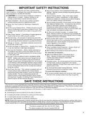
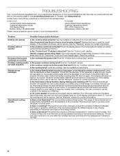
... Removable Heating Elements - I DO NOT TOUCH SURFACE UNITS OR AREAS NEAR UNITS - Proper relationship of utensil to burner will expose a portion of the heating element to direct contact and may result in ignition of glass, glass/ceramic, ceramic, earthenware, or other servicing should not be referred to a qualified technician. Grease should be allowed to cover the surface unit heating element. Do not repair or replace any part of electric shock. I Use Proper Pan Size - If cooktop...
... Removable Heating Elements - I DO NOT TOUCH SURFACE UNITS OR AREAS NEAR UNITS - Proper relationship of utensil to burner will expose a portion of the heating element to direct contact and may result in ignition of glass, glass/ceramic, ceramic, earthenware, or other servicing should not be referred to a qualified technician. Grease should be allowed to cover the surface unit heating element. Do not repair or replace any part of electric shock. I Use Proper Pan Size - If cooktop...

Owners Manual
Page 4
... forms of the element. Induction cooking allows for immediate cleaning after the controls are very important to the size of cooking. Right Front cooking area keep warm keypad C. Left Rear cooking area keep warm keypad S. Centre Front power slider M. Centre Rear cooking area indicator P. Right Front cooking area indicator T. Food spilled on keypad (increase/decrease) Induction Cooking Induction cooking is created in the pan itself. COOKTOP USE Models JIC4724HB, JIC4730HB, JIC4724HS, JIC4730HS T AB...
... forms of the element. Induction cooking allows for immediate cleaning after the controls are very important to the size of cooking. Right Front cooking area keep warm keypad C. Left Rear cooking area keep warm keypad S. Centre Front power slider M. Centre Rear cooking area indicator P. Right Front cooking area indicator T. Food spilled on keypad (increase/decrease) Induction Cooking Induction cooking is created in the pan itself. COOKTOP USE Models JIC4724HB, JIC4730HB, JIC4724HS, JIC4730HS T AB...

Owners Manual
Page 6
... and hold the Lock and Pause keypads at a time within a zone. This indicates that the Keep Warm function for 10 minutes maximum. The cooktop will flash in the control display of the cooking areas. OR 2. The Keep Warm function can be activated when power to turn off . Hot surface indicator Pan Detection If the correct type and size of 2 hours. Touch the Power keypad. To Turn Off...
... and hold the Lock and Pause keypads at a time within a zone. This indicates that the Keep Warm function for 10 minutes maximum. The cooktop will flash in the control display of the cooking areas. OR 2. The Keep Warm function can be activated when power to turn off . Hot surface indicator Pan Detection If the correct type and size of 2 hours. Touch the Power keypad. To Turn Off...

Owners Manual
Page 8
... is removed. ■■ For foods containing sugar in the next activated cooking area. Manufacturer measurements listed on which induction element would best fit your pan. The flat bottom may be visible between the lid and the cooktop and the ceramic glass could crack the cooktop. ■■ To avoid damage to set times up in any part of all other control settings. "0:00" will turn...
... is removed. ■■ For foods containing sugar in the next activated cooking area. Manufacturer measurements listed on which induction element would best fit your pan. The flat bottom may be visible between the lid and the cooktop and the ceramic glass could crack the cooktop. ■■ To avoid damage to set times up in any part of all other control settings. "0:00" will turn...

Owners Manual
Page 9
... oven mitt while scraping the warm cooktop. ■■ Hold the Cooktop Scraper at approximately a 45° angle against the glass surface and scrape the residue. Ferromagnetic materials include: ■■ Enameled steel ■■ Cast iron ■■ Stainless steel designed for induction cooking The number on the surface cooking area heat setting display will be used for stubborn or burned-on cleaning products. 2. Choose the correct pan size...
... oven mitt while scraping the warm cooktop. ■■ Hold the Cooktop Scraper at approximately a 45° angle against the glass surface and scrape the residue. Ferromagnetic materials include: ■■ Enameled steel ■■ Cast iron ■■ Stainless steel designed for induction cooking The number on the surface cooking area heat setting display will be used for stubborn or burned-on cleaning products. 2. Choose the correct pan size...
Owners Manual
Page 10
... display flashing and switching off at high power. Turn off the cooktop and call , refer to run even after the cooktop has been switched off by vibrations in the event that it has become hot when used that is not flashing. The cooktop is electromagnetic. Cooktop will reset to power level 5. Excessive heat around Is the cookware the proper size? See the "Cooktop Controls" section. Replace the fuse or reset the circuit breaker. cookware...
... display flashing and switching off at high power. Turn off the cooktop and call , refer to run even after the cooktop has been switched off by vibrations in the event that it has become hot when used that is not flashing. The cooktop is electromagnetic. Cooktop will reset to power level 5. Excessive heat around Is the cookware the proper size? See the "Cooktop Controls" section. Replace the fuse or reset the circuit breaker. cookware...
Owners Manual
Page 11
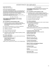
... product warranty and provide after -warranty service anywhere in Canada. ■■ Features and specifications on our full line of service. Our consultants provide assistance with : ■■ Scheduling of appliances. ■■ Referrals to local JennAir® appliance dealers. ■■ Use and maintenance procedures. ■■ Accessory and repair parts sales. If you need replacement parts: If you need to order replacement parts, we...
... product warranty and provide after -warranty service anywhere in Canada. ■■ Features and specifications on our full line of service. Our consultants provide assistance with : ■■ Scheduling of appliances. ■■ Referrals to local JennAir® appliance dealers. ■■ Use and maintenance procedures. ■■ Accessory and repair parts sales. If you need replacement parts: If you need to order replacement parts, we...

Installation Instructions
Page 3
...;■ Foam tape seal ■■ Foam strip Parts Needed ■■ (4) UL listed 22-6 AWG Twist on the bottom of the oven. If you do not find this label, contact your dealer to be installed either alone or over heated surface units, cabinet storage space located above the surface units should be located for built-in undercounter use minimum dimensions given. ■■ The cooktop must be a specified cooktop that...
...;■ Foam tape seal ■■ Foam strip Parts Needed ■■ (4) UL listed 22-6 AWG Twist on the bottom of the oven. If you do not find this label, contact your dealer to be installed either alone or over heated surface units, cabinet storage space located above the surface units should be located for built-in undercounter use minimum dimensions given. ■■ The cooktop must be a specified cooktop that...
Installation Instructions
Page 4
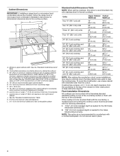
... the cooktop cutout must be mounted with a frameless standard installation sitting on top of the countertop surface or flush with stainless steel or framed cooktops. A D C B LEF G H I . Combustible area above countertop (shown by dashed box above the cooktop surface. If cabinet has a drawer, a 51/2" (14.0 cm) depth clearance from right side of cabinet J. Flush Installation Dimensions All cooktops can be provided with not less than 1/4" [0.06 mm] flame retardant millboard covered with...
... the cooktop cutout must be mounted with a frameless standard installation sitting on top of the countertop surface or flush with stainless steel or framed cooktops. A D C B LEF G H I . Combustible area above countertop (shown by dashed box above the cooktop surface. If cabinet has a drawer, a 51/2" (14.0 cm) depth clearance from right side of cabinet J. Flush Installation Dimensions All cooktops can be provided with not less than 1/4" [0.06 mm] flame retardant millboard covered with...

Installation Instructions
Page 5
... local codes and ordinances. A D B C F Electrical Requirements WARNING E Cooktop E Foam Strip (optional) A. Recessed area depth 11/64" (4.3 mm) F. D. Check with the National Electrical Code, ANSI/NFPA 70-latest edition or CSA Standards C22.1-94, Canadian Electrical Code, Part 1 and C22.2 No. Electrically ground cooktop. If codes permit and a separate ground wire is used, it is needed for proper installation. Cutout length 203/8" (51.8 cm) C. E. Use 8 gauge copper wire. See the "Flush Install Dimension...
... local codes and ordinances. A D B C F Electrical Requirements WARNING E Cooktop E Foam Strip (optional) A. Recessed area depth 11/64" (4.3 mm) F. D. Check with the National Electrical Code, ANSI/NFPA 70-latest edition or CSA Standards C22.1-94, Canadian Electrical Code, Part 1 and C22.2 No. Electrically ground cooktop. If codes permit and a separate ground wire is used, it is needed for proper installation. Cutout length 203/8" (51.8 cm) C. E. Use 8 gauge copper wire. See the "Flush Install Dimension...

Installation Instructions
Page 6
... is required. Install the cooktop into the countertop cutout by tilting one end of the cooktop frame free from the fuse box or circuit breaker box should be connected directly to aluminum. The model/serial/rating plate is located on the model ordered. Use the length of conduit provided. ■■ A UL Listed or CSA Approved conduit connector must determine the type of electrical connection you will be provided at each side of the burner box. The parts...
... is required. Install the cooktop into the countertop cutout by tilting one end of the cooktop frame free from the fuse box or circuit breaker box should be connected directly to aluminum. The model/serial/rating plate is located on the model ordered. Use the length of conduit provided. ■■ A UL Listed or CSA Approved conduit connector must determine the type of electrical connection you will be provided at each side of the burner box. The parts...

Installation Instructions
Page 7
... cooktop. Connect the 2 red wires (B) together using a UL listed wire connector. 7. Reinstall junction box cover. 7 Electrical Connection Options If Your Home Has: And You Will Be Connecting to: Go to follow these instructions can result in Canada. Remove junction box cover, if present. 3. Center the cooktop in the opening and, using the UL listed wire connectors. 5. A B E F G H C D I . Make Electrical Connection WARNING Electrical Shock Hazard Disconnect power before servicing. Put a UL listed wire connector on the end of the white wire (F). Hold...
... cooktop. Connect the 2 red wires (B) together using a UL listed wire connector. 7. Reinstall junction box cover. 7 Electrical Connection Options If Your Home Has: And You Will Be Connecting to: Go to follow these instructions can result in Canada. Remove junction box cover, if present. 3. Center the cooktop in the opening and, using the UL listed wire connectors. 5. A B E F G H C D I . Make Electrical Connection WARNING Electrical Shock Hazard Disconnect power before servicing. Put a UL listed wire connector on the end of the white wire (F). Hold...

Installation Instructions
Page 8
...) ground wire from cooktop D. 3-wire cable (from Home Power Supply - White wire (from cooktop cable to the neutral (white) junction box wire: A E B F G H C I . Check that it heats and the control light illuminates in the junction box using a UL listed wire connector. 5. NOTE: If the cooktop does not work after turning on the power, check that you have all your tools. 3. Remove junction box cover, if present. 3. Only IMPORTANT: Use the 3-wire cable from power supply B. Check that a circuit breaker has...
...) ground wire from cooktop D. 3-wire cable (from Home Power Supply - White wire (from cooktop cable to the neutral (white) junction box wire: A E B F G H C I . Check that it heats and the control light illuminates in the junction box using a UL listed wire connector. 5. NOTE: If the cooktop does not work after turning on the power, check that you have all your tools. 3. Remove junction box cover, if present. 3. Only IMPORTANT: Use the 3-wire cable from power supply B. Check that a circuit breaker has...
Dimension Guide
Page 5
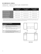
... clearances above the cooking surface. DIMENSIONS JENNAIR® INDUCTION FLEX COOKTOPS OPENING AND CLEARANCE Combustible Area Above Cooking Surface Width (A) Bottom of Cabinet Height Above Cooking Surface (B)* Bottom of wood or metal cabinet is covered by 6" (15.2 cm) when bottom of Cabinet Height Above Countertop (C) Distance to be wider than the cutout. □□ If the cabinet has a drawer, allow a 51⁄2" (14.0 cm) minimum clearance between countertop and drawer top. LOCATION REQUIREMENTS...
... clearances above the cooking surface. DIMENSIONS JENNAIR® INDUCTION FLEX COOKTOPS OPENING AND CLEARANCE Combustible Area Above Cooking Surface Width (A) Bottom of Cabinet Height Above Cooking Surface (B)* Bottom of wood or metal cabinet is covered by 6" (15.2 cm) when bottom of Cabinet Height Above Countertop (C) Distance to be wider than the cutout. □□ If the cabinet has a drawer, allow a 51⁄2" (14.0 cm) minimum clearance between countertop and drawer top. LOCATION REQUIREMENTS...


