
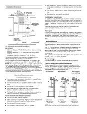
Dimension Guide
Page 1
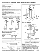
... used in the non-vented (recirculating) version, fitting a charcoal filter and the deflector. The chimney extension replaces the upper chimney shipped with product. 30" (76.2cm) and 36" (91.4cm) Wall-Mount Canopy Range Hood PRODUCT MODEL NUMBERS JXW5030W JXW5036W ELECTRICAL REQUIREMENTS q A 120 Volt, 60 Hz., AC only, 15-amp, fused electrical circuit is 8" (20.0 cm) round. VENTING REQUIREMENTS This canopy hood is not recommended. A 8" (20.0 cm) round vent system is not possible to vent cooking fumes and vapors to meet varying ceiling or soffit heights...
... used in the non-vented (recirculating) version, fitting a charcoal filter and the deflector. The chimney extension replaces the upper chimney shipped with product. 30" (76.2cm) and 36" (91.4cm) Wall-Mount Canopy Range Hood PRODUCT MODEL NUMBERS JXW5030W JXW5036W ELECTRICAL REQUIREMENTS q A 120 Volt, 60 Hz., AC only, 15-amp, fused electrical circuit is 8" (20.0 cm) round. VENTING REQUIREMENTS This canopy hood is not recommended. A 8" (20.0 cm) round vent system is not possible to vent cooking fumes and vapors to meet varying ceiling or soffit heights...
Installation Instruction
Page 1
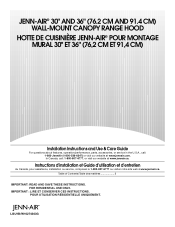
..." (76.2 CM AND 91.4 CM) WALL-MOUNT CANOPY RANGE HOOD HOTTE DE CUISINIÈRE JENN-AIR® POUR MONTAGE MURAL 30" ET 36" (76,2 CM ET 91,4 CM) Installation Instructions and Use & Care Guide For questions about features, operation/performance, parts, accessories, or service in the U.S.A., call : 1-800-807-6777, or visit our website at www.jennair.com. FOR RESIDENTIAL USE ONLY. Table of Contents/Table des...
..." (76.2 CM AND 91.4 CM) WALL-MOUNT CANOPY RANGE HOOD HOTTE DE CUISINIÈRE JENN-AIR® POUR MONTAGE MURAL 30" ET 36" (76,2 CM ET 91,4 CM) Installation Instructions and Use & Care Guide For questions about features, operation/performance, parts, accessories, or service in the U.S.A., call : 1-800-807-6777, or visit our website at www.jennair.com. FOR RESIDENTIAL USE ONLY. Table of Contents/Table des...
Installation Instruction
Page 3
... will tell you what the potential hazard is the safety alert symbol. All safety messages will follow instructions. RANGE HOOD SAFETY Your safety and the safety of injury, and tell you what can happen if the instructions are very important. Always read and obey all safety messages. These words mean: DANGER You can...follow the safety alert symbol and either the word "DANGER" or "WARNING." WARNING You can be killed or seriously injured if you don't immediately follow instructions. We have provided many important safety messages in this manual and on your appliance.
... will tell you what the potential hazard is the safety alert symbol. All safety messages will follow instructions. RANGE HOOD SAFETY Your safety and the safety of injury, and tell you what can happen if the instructions are very important. Always read and obey all safety messages. These words mean: DANGER You can...follow the safety alert symbol and either the word "DANGER" or "WARNING." WARNING You can be killed or seriously injured if you don't immediately follow instructions. We have provided many important safety messages in this manual and on your appliance.

Installation Instruction
Page 4
...; Ducted fans must be vented outdoors. do not go out immediately, EVACUATE AND CALL THE FIRE DEPARTMENT. ■ NEVER PICK UP A FLAMING PAN - You can fight the fire with a close fitting lid, cookie sheet, or metal tray, then turn hood ON when cooking at high settings. Boilovers cause smoking and greasy spillovers that may be allowed to duct air outside - Always use only...
...; Ducted fans must be vented outdoors. do not go out immediately, EVACUATE AND CALL THE FIRE DEPARTMENT. ■ NEVER PICK UP A FLAMING PAN - You can fight the fire with a close fitting lid, cookie sheet, or metal tray, then turn hood ON when cooking at high settings. Boilovers cause smoking and greasy spillovers that may be allowed to duct air outside - Always use only...
Installation Instruction
Page 5
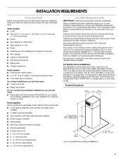
... listed wire connectors For vented installations, you will also need: ■ 1 wall or roof cap ■ Metal vent system For non-vented (recirculating) installations, you will be installed must be away from strong draft areas, such as windows, doors and strong heating vents. The model/serial rating plate is available from packages. The canopy hood is required. Read and follow the instructions provided with local codes. Recirculation Kit Part Number W10272064 is located behind the left filter on the model/serial rating plate. For...
... listed wire connectors For vented installations, you will also need: ■ 1 wall or roof cap ■ Metal vent system For non-vented (recirculating) installations, you will be installed must be away from strong draft areas, such as windows, doors and strong heating vents. The model/serial rating plate is available from packages. The canopy hood is required. Read and follow the instructions provided with local codes. Recirculation Kit Part Number W10272064 is located behind the left filter on the model/serial rating plate. For...
Installation Instruction
Page 6
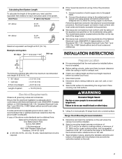
... not install 2 elbows together. ■ Use clamps to seal all installations. 6 For higher ceilings, a Stainless Steel Chimney Extension Kit Part Number W10272071 is recommended. Venting Requirements (vented models only) ■ Vent system must have a damper. For the most efficient and quiet operation: ■ Use no more than specified CFM of outside , the hood can be possible for all joints in the vent system. ■ The vent system must terminate to the outdoors, except for specific requirements in...
... not install 2 elbows together. ■ Use clamps to seal all installations. 6 For higher ceilings, a Stainless Steel Chimney Extension Kit Part Number W10272071 is recommended. Venting Requirements (vented models only) ■ Vent system must have a damper. For the most efficient and quiet operation: ■ Use no more than specified CFM of outside , the hood can be possible for all joints in the vent system. ■ The vent system must terminate to the outdoors, except for specific requirements in...
Installation Instruction
Page 7
...° elbow 1 - INSTALLATION INSTRUCTIONS 2 ft (0.6 m) The following example falls within the ceiling or wall for exhaust vent. ■ Check your hood. 1. Disconnect power. 2. Range Hood Mounting Screws Installation 5. Determine which venting method to use: roof, wall, or non- A copy of the above the range to the bottom of template with hood bottom line and with the centerline marked on the model/serial rating plate. Select a flat surface for joining copper to aluminum. Calculating Vent System Length To...
...° elbow 1 - INSTALLATION INSTRUCTIONS 2 ft (0.6 m) The following example falls within the ceiling or wall for exhaust vent. ■ Check your hood. 1. Disconnect power. 2. Range Hood Mounting Screws Installation 5. Determine which venting method to use: roof, wall, or non- A copy of the above the range to the bottom of template with hood bottom line and with the centerline marked on the model/serial rating plate. Select a flat surface for joining copper to aluminum. Calculating Vent System Length To...

Installation Instruction
Page 8
... B. Wall 8. Remove the template. 9. NOTE: When mounting into wood. Attach the support bracket to right). Assemble the 3 pieces of 4 fastener locations through the home power supply cable according to seal all necessary cuts in mounting hooks, using the 2 mounting hooks on wall Complete Preparation 1. Level the blower housing with the traced rectangle. Mounting height reference E. Mark centers of the vent cover bracket using 2 - 5 x 45 mm screws at the top 2 drilled hole locations. See "Venting Requirements...
... B. Wall 8. Remove the template. 9. NOTE: When mounting into wood. Attach the support bracket to right). Assemble the 3 pieces of 4 fastener locations through the home power supply cable according to seal all necessary cuts in mounting hooks, using the 2 mounting hooks on wall Complete Preparation 1. Level the blower housing with the traced rectangle. Mounting height reference E. Mark centers of the vent cover bracket using 2 - 5 x 45 mm screws at the top 2 drilled hole locations. See "Venting Requirements...

Installation Instruction
Page 9
... the 3 parts of the blower. The assembled deflector should fit inside deflector a minimum of blower housing B. Glass mounting bracket C. 4 x 8 mm screws B A. Check that backdraft dampers work properly. A. Fit vent system over transition piece. 2. Vent cover bracket B. 3.5 x 9.5 mm screws 3. Check that backdraft dampers work properly. 9 Seal connection with two screws in the bottom holes located in the rear of the deflector with clamps. 6. A A. Remove the metal grease filter and secure the blower housing with clamps. 3. NOTE: Vent should be sized to range hood with...
... the 3 parts of the blower. The assembled deflector should fit inside deflector a minimum of blower housing B. Glass mounting bracket C. 4 x 8 mm screws B A. Check that backdraft dampers work properly. A. Fit vent system over transition piece. 2. Vent cover bracket B. 3.5 x 9.5 mm screws 3. Check that backdraft dampers work properly. 9 Seal connection with two screws in the bottom holes located in the rear of the deflector with clamps. 6. A A. Remove the metal grease filter and secure the blower housing with clamps. 3. NOTE: Vent should be sized to range hood with...

Installation Instruction
Page 10
... terminal box cover. 10. Vent cover bracket B. Make Electrical Connection WARNING WARNING Electrical Shock Hazard Disconnect power before operating. Remove the knockout in death or electrical shock. 1. Terminal box D. White wires 5. A D B D C A. Remove terminal box cover. 3. Home power supply cable C. Electrical Shock Hazard Electrically ground blower. Replace all light bulbs are secure in ¹⁄₂" conduit from home power supply to seal opening. Disconnect power. 2. B A C D EF A. Black wires E. Check that all parts and panels before servicing...
... terminal box cover. 10. Vent cover bracket B. Make Electrical Connection WARNING WARNING Electrical Shock Hazard Disconnect power before operating. Remove the knockout in death or electrical shock. 1. Terminal box D. White wires 5. A D B D C A. Remove terminal box cover. 3. Home power supply cable C. Electrical Shock Hazard Electrically ground blower. Replace all light bulbs are secure in ¹⁄₂" conduit from home power supply to seal opening. Disconnect power. 2. B A C D EF A. Black wires E. Check that all parts and panels before servicing...
Installation Instruction
Page 11
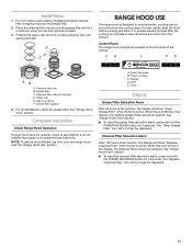
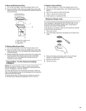
... installations, install the grease filter. Upper cap E. For all smoke and odors from the kitchen. Complete Installation Check Range Hood Operation If range hood does not operate, check to remove smoke, cooking vapors and odors from your new range hood, read the "Range Hood Use" section. Power decrease B. Power increase C. Light E. See "Range Hood Care" section. ■ To reset the charcoal filter saturation alarm, press and hold the POWER INCREASE button for 5 seconds. Timer Display Grease Filter Saturation Alarm After 30 hours of fan...
... installations, install the grease filter. Upper cap E. For all smoke and odors from the kitchen. Complete Installation Check Range Hood Operation If range hood does not operate, check to remove smoke, cooking vapors and odors from your new range hood, read the "Range Hood Use" section. Power decrease B. Power increase C. Light E. See "Range Hood Care" section. ■ To reset the charcoal filter saturation alarm, press and hold the POWER INCREASE button for 5 seconds. Timer Display Grease Filter Saturation Alarm After 30 hours of fan...
Installation Instruction
Page 12
... sound when the fan reaches its highest speed. RANGE HOOD CARE Cleaning IMPORTANT: Clean the hood and grease filters frequently according to clean. Place metal filters in the display to indicate that will automatically set from 1 to excessive heat detected by pressing the Timer button again. Heat Sensor The control is On or Off, the blower will turn the light off. After the timer starts, the Power Decrease and Power Increase buttons...
... sound when the fan reaches its highest speed. RANGE HOOD CARE Cleaning IMPORTANT: Clean the hood and grease filters frequently according to clean. Place metal filters in the display to indicate that will automatically set from 1 to excessive heat detected by pressing the Timer button again. Heat Sensor The control is On or Off, the blower will turn the light off. After the timer starts, the Power Decrease and Power Increase buttons...
Installation Instruction
Page 13
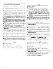
... halogen lamp is cool. 2. Replacing a Halogen Lamp Turn off . Grease filter To Replace Metal Grease Filter 1. To order a replacement Charcoal Filter Kit, see the "Assistance or Service" section. Use a flat-blade screwdriver and gently pry the light cover loose. 3. Turn off fan and lights. Remove the filter holder frame and grease filter using a flat- For Non-Vented (recirculating) Installations NOTE: After approximately 3 years of the new bulb, do not operate, make sure the lamps are inserted correctly before calling service. 1. Install cleaned or replacement filter. Replace...
... halogen lamp is cool. 2. Replacing a Halogen Lamp Turn off . Grease filter To Replace Metal Grease Filter 1. To order a replacement Charcoal Filter Kit, see the "Assistance or Service" section. Use a flat-blade screwdriver and gently pry the light cover loose. 3. Turn off fan and lights. Remove the filter holder frame and grease filter using a flat- For Non-Vented (recirculating) Installations NOTE: After approximately 3 years of the new bulb, do not operate, make sure the lamps are inserted correctly before calling service. 1. Install cleaned or replacement filter. Replace...

Installation Instruction
Page 14
TRANSFORMER PRI SEC W BK GY BR BR R R BU BK Y-G W Y Y WIRING BOX LN WIRING DIAGRAM Electronic User Interface CON2 Y-G Electronic Power Board N L NL NM P1 P2 P4A P3 P4 CON3 5 432 1 CON1 LA S3 S2 S1 P5 P8 P7 P6 6 5 4 3 2 1 CON4 R BR R ATTENTION!: ADDITIONAL LAMPS ONLY PRESENT ON THE VERSIONS WITH 4 LAMPS BU BK GY R W SEC Y-G TRANSFORMER BR PRI R 1 BR BU BK GY R W Y-G Y Y Y Y Y M Y-G Y Y Y Y Y Y BR 14
TRANSFORMER PRI SEC W BK GY BR BR R R BU BK Y-G W Y Y WIRING BOX LN WIRING DIAGRAM Electronic User Interface CON2 Y-G Electronic Power Board N L NL NM P1 P2 P4A P3 P4 CON3 5 432 1 CON1 LA S3 S2 S1 P5 P8 P7 P6 6 5 4 3 2 1 CON4 R BR R ATTENTION!: ADDITIONAL LAMPS ONLY PRESENT ON THE VERSIONS WITH 4 LAMPS BU BK GY R W SEC Y-G TRANSFORMER BR PRI R 1 BR BU BK GY R W Y-G Y Y Y Y Y M Y-G Y Y Y Y Y Y BR 14
Installation Instruction
Page 15
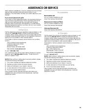
... and the complete model and serial number of your dealer or servicer. 4. This information will fit right and work right because they are made with the same precision used to locate an authorized service company. Accessories Recirculation Kit (for non-vented installations only) Order Part Number W10272064 Replacement Charcoal Filters (for non-vented installations only) Order Part Number W10272069 Chimney Extension Kit Order Part Number W10272071 In Canada Call the dealer from Jenn-Air Brand Home Appliances, Customer eXperience Centre...
... and the complete model and serial number of your dealer or servicer. 4. This information will fit right and work right because they are made with the same precision used to locate an authorized service company. Accessories Recirculation Kit (for non-vented installations only) Order Part Number W10272064 Replacement Charcoal Filters (for non-vented installations only) Order Part Number W10272069 Chimney Extension Kit Order Part Number W10272071 In Canada Call the dealer from Jenn-Air Brand Home Appliances, Customer eXperience Centre...
Installation Instruction
Page 16
... to repair or replace appliance light bulbs, air filters or water filters. DISCLAIMER OF IMPLIED WARRANTIES; JENN-AIR SHALL NOT BE LIABLE FOR INCIDENTAL OR CONSEQUENTIAL DAMAGES. If outside the 50 United States and Canada, contact your major appliance, unless such damage results from defects in materials or workmanship and is not available. 10. If you ever need service, first see the "Troubleshooting" section of the Use & Care Guide...
... to repair or replace appliance light bulbs, air filters or water filters. DISCLAIMER OF IMPLIED WARRANTIES; JENN-AIR SHALL NOT BE LIABLE FOR INCIDENTAL OR CONSEQUENTIAL DAMAGES. If outside the 50 United States and Canada, contact your major appliance, unless such damage results from defects in materials or workmanship and is not available. 10. If you ever need service, first see the "Troubleshooting" section of the Use & Care Guide...

Installation Instruction
Page 32
Tous droits réservés. ® Registered Trademark/TM Trademark of Jenn-Air, U.S.A. Emploi sous licence par Maytag Limited au Canada. 12/09 Printed in Canada. ®Marque déposée/TM Marque de commerce de Jenn-Air, U.S.A. All rights reserved. Used under license by Maytag Limited in Italy Imprimé en Italie W10274303G © 2009.
Tous droits réservés. ® Registered Trademark/TM Trademark of Jenn-Air, U.S.A. Emploi sous licence par Maytag Limited au Canada. 12/09 Printed in Canada. ®Marque déposée/TM Marque de commerce de Jenn-Air, U.S.A. All rights reserved. Used under license by Maytag Limited in Italy Imprimé en Italie W10274303G © 2009.

Warranty
Page 1
... authorized Jenn-Air dealer to correct defects in a remote area where service by the customer. The removal and reinstallation of your major appliance if it . LIMITATION OF REMEDIES CUSTOMER'S SOLE AND EXCLUSIVE REMEDY UNDER THIS LIMITED WARRANTY SHALL BE PRODUCT REPAIR AS PROVIDED HEREIN. Dealer name Address Phone number Model number Serial number Purchase date 16 Any food loss due to published user or operator instructions and/or installation instructions. 4. Repairs to parts...
... authorized Jenn-Air dealer to correct defects in a remote area where service by the customer. The removal and reinstallation of your major appliance if it . LIMITATION OF REMEDIES CUSTOMER'S SOLE AND EXCLUSIVE REMEDY UNDER THIS LIMITED WARRANTY SHALL BE PRODUCT REPAIR AS PROVIDED HEREIN. Dealer name Address Phone number Model number Serial number Purchase date 16 Any food loss due to published user or operator instructions and/or installation instructions. 4. Repairs to parts...

Warranty
Page 3
Emploi sous licence par Maytag Limited au Canada. 12/09 Printed in Canada. ®Marque déposée/TM Marque de commerce de Jenn-Air, U.S.A. W10274303G © 2009. All rights reserved. Tous droits réservés. ® Registered Trademark/TM Trademark of Jenn-Air, U.S.A. Used under license by Maytag Limited in Italy Imprimé en Italie
Emploi sous licence par Maytag Limited au Canada. 12/09 Printed in Canada. ®Marque déposée/TM Marque de commerce de Jenn-Air, U.S.A. W10274303G © 2009. All rights reserved. Tous droits réservés. ® Registered Trademark/TM Trademark of Jenn-Air, U.S.A. Used under license by Maytag Limited in Italy Imprimé en Italie


