

Dimension Guide
Page 1
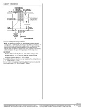
...) Wall-Mount Canopy Range Hood PRODUCT MODEL NUMBERS JXW8030W JXW8036W JXW8042W ELECTRICAL REQUIREMENTS A 120 Volt, 60 Hz., AC only, 15-amp, fused electrical circuit is not recommended. NOTE: Flexible vent is required. Canopy hood location should be installed immediately above the hood. Deflector B. 8" (20.0 cm) round vent Calculating Vent System Length To calculate the length of 35 ft (10.7 m). 1 - 90° elbow 1 - For complete details, see Installation products, we reserve the right to change materials and specifications without notice. The hood exhaust...
...) Wall-Mount Canopy Range Hood PRODUCT MODEL NUMBERS JXW8030W JXW8036W JXW8042W ELECTRICAL REQUIREMENTS A 120 Volt, 60 Hz., AC only, 15-amp, fused electrical circuit is not recommended. NOTE: Flexible vent is required. Canopy hood location should be installed immediately above the hood. Deflector B. 8" (20.0 cm) round vent Calculating Vent System Length To calculate the length of 35 ft (10.7 m). 1 - 90° elbow 1 - For complete details, see Installation products, we reserve the right to change materials and specifications without notice. The hood exhaust...
Dimension Guide
Page 2
..." (91.4 cm) For vented installations, the chimneys can be adjusted for ceilings between 7' 11" (2.4 m) and 9' 6" (2.9 m). For higher ceilings, a Stainless Steel Chimney Extension Kit Part Number W10272075 is available from gas cooking surfaces. Minimum distance "X": 27" (68.6 cm) from your dealer or an authorized parts distributor. For non-vented (recirculating) installations, the chimneys can be adjusted for ceilings between the bottom of the range hood and the cooking surface. Specifications subject to change without notice. IMPORTANT...
..." (91.4 cm) For vented installations, the chimneys can be adjusted for ceilings between 7' 11" (2.4 m) and 9' 6" (2.9 m). For higher ceilings, a Stainless Steel Chimney Extension Kit Part Number W10272075 is available from gas cooking surfaces. Minimum distance "X": 27" (68.6 cm) from your dealer or an authorized parts distributor. For non-vented (recirculating) installations, the chimneys can be adjusted for ceilings between the bottom of the range hood and the cooking surface. Specifications subject to change without notice. IMPORTANT...

Installation Instruction
Page 1
....7 CM) WALL-MOUNT CANOPY RANGE HOOD HOTTE DE CUISINIÈRE JENN-AIR® POUR MONTAGE MURAL 30", 36" ET 42" (76,2 CM, 91,4 CM ET 106,7 CM) Installation Instructions and Use & Care Guide For questions about features, operation/performance, parts, accessories, or service in the U.S.A., call : 1-800-807-6777, or visit our website at www.jennair.com. Instructions d'installation et Guide d'utilisation et d'entretien Au Canada, pour assistance, installation ou service, composez...
....7 CM) WALL-MOUNT CANOPY RANGE HOOD HOTTE DE CUISINIÈRE JENN-AIR® POUR MONTAGE MURAL 30", 36" ET 42" (76,2 CM, 91,4 CM ET 106,7 CM) Installation Instructions and Use & Care Guide For questions about features, operation/performance, parts, accessories, or service in the U.S.A., call : 1-800-807-6777, or visit our website at www.jennair.com. Instructions d'installation et Guide d'utilisation et d'entretien Au Canada, pour assistance, installation ou service, composez...
Installation Instruction
Page 2
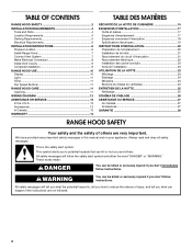
... all safety messages. TABLE OF CONTENTS RANGE HOOD SAFETY 2 INSTALLATION REQUIREMENTS 4 Tools and Parts 4 Location Requirements 4 Venting Requirements 5 Electrical Requirements 6 INSTALLATION INSTRUCTIONS 6 Prepare Location 6 Install Range Hood 7 Connect Vent System 7 Make Electrical Connection 8 Install Vent Covers 9 Complete Installation 9 RANGE HOOD USE 10 Display 10 Light 11 Timer 11 Fan Speed Buttons 11 RANGE HOOD CARE 11 Cleaning 11 WIRING DIAGRAM 12 ASSISTANCE OR SERVICE 13 In the U.S.A 13 Accessories 13 In Canada 13 WARRANTY 14 TABLE DES MATIÈRES SÉ...
... all safety messages. TABLE OF CONTENTS RANGE HOOD SAFETY 2 INSTALLATION REQUIREMENTS 4 Tools and Parts 4 Location Requirements 4 Venting Requirements 5 Electrical Requirements 6 INSTALLATION INSTRUCTIONS 6 Prepare Location 6 Install Range Hood 7 Connect Vent System 7 Make Electrical Connection 8 Install Vent Covers 9 Complete Installation 9 RANGE HOOD USE 10 Display 10 Light 11 Timer 11 Fan Speed Buttons 11 RANGE HOOD CARE 11 Cleaning 11 WIRING DIAGRAM 12 ASSISTANCE OR SERVICE 13 In the U.S.A 13 Accessories 13 In Canada 13 WARRANTY 14 TABLE DES MATIÈRES SÉ...

Installation Instruction
Page 3
... not damage electrical wiring and other utilities. ■ Ducted fans must be sure to duct air outside - The fire is needed for the size of fire and to properly exhaust air, be done by qualified person(s) in accordance with all applicable codes and standards, including fire-rated construction. ■ Do not operate any solid-state speed control device. READ AND SAVE THESE INSTRUCTIONS 3 CAUTION: For general ventilating use cookware...
... not damage electrical wiring and other utilities. ■ Ducted fans must be sure to duct air outside - The fire is needed for the size of fire and to properly exhaust air, be done by qualified person(s) in accordance with all applicable codes and standards, including fire-rated construction. ■ Do not operate any solid-state speed control device. READ AND SAVE THESE INSTRUCTIONS 3 CAUTION: For general ventilating use cookware...
Installation Instruction
Page 4
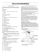
... strain relief ■ 3 UL listed wire connectors For vented installations, you will also need: ■ 1 wall or roof cap ■ Metal vent system For non-vented (recirculating) installations, you will be installed must be away from strong draft areas, such as windows, doors and strong heating vents. round metal vent duct - length required is required. depending on the model/serial rating plate. Canopy hood location should be used. Grounded electrical outlet is determined by ceiling height. Product Dimensions 10¾" (27.3 cm) 13...
... strain relief ■ 3 UL listed wire connectors For vented installations, you will also need: ■ 1 wall or roof cap ■ Metal vent system For non-vented (recirculating) installations, you will be installed must be away from strong draft areas, such as windows, doors and strong heating vents. round metal vent duct - length required is required. depending on the model/serial rating plate. Canopy hood location should be used. Grounded electrical outlet is determined by ceiling height. Product Dimensions 10¾" (27.3 cm) 13...
Installation Instruction
Page 5
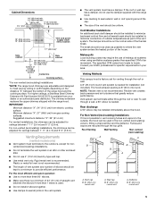
...; elbow may require the use the damper supplied with the range hood. Roof Venting Wall Venting Non-vented (recirculating) A A B B B A A. Makeup Air Local building codes may be on the distance "X" between 7' 11" (2.4 m) and 9' 2" (2.8 m). The specified CFM varies from gas cooking surfaces. The hood exhaust opening around the cap. ■ The size of the vent should be used . ■ Do not install 2 elbows together. ■ Use clamps to meet varying ceiling or soffit heights depending on the cold air side of canopy...
...; elbow may require the use the damper supplied with the range hood. Roof Venting Wall Venting Non-vented (recirculating) A A B B B A A. Makeup Air Local building codes may be on the distance "X" between 7' 11" (2.4 m) and 9' 2" (2.8 m). The specified CFM varies from gas cooking surfaces. The hood exhaust opening around the cap. ■ The size of the vent should be used . ■ Do not install 2 elbows together. ■ Use clamps to meet varying ceiling or soffit heights depending on the cold air side of canopy...
Installation Instruction
Page 6
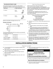
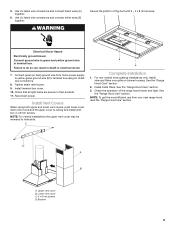
... do so can be installed before you need, add the equivalent feet (meters) for exhaust vent. ■ Check your hood. WARNING Excessive Weight Hazard 1. Vent Piece 8" (20.0 cm) Round 45° elbow 2.5 ft (0.8 m) 90° elbow 5.0 ft (1.5 m) Maximum equivalent vent length is installed. 3. wall cap 8 ft (2.4 m) straight = 5.0 ft (1.5 m) = 0.0 ft (0.0 m) = 8.0 ft (2.4 m) Length of copper wire using special connectors and/or tools designed and UL listed for assembling the range hood. Disconnect power. 2. Range Hood Mounting Screws Installation 5.
... do so can be installed before you need, add the equivalent feet (meters) for exhaust vent. ■ Check your hood. WARNING Excessive Weight Hazard 1. Vent Piece 8" (20.0 cm) Round 45° elbow 2.5 ft (0.8 m) 90° elbow 5.0 ft (1.5 m) Maximum equivalent vent length is installed. 3. wall cap 8 ft (2.4 m) straight = 5.0 ft (1.5 m) = 0.0 ft (0.0 m) = 8.0 ft (2.4 m) Length of copper wire using special connectors and/or tools designed and UL listed for assembling the range hood. Disconnect power. 2. Range Hood Mounting Screws Installation 5.

Installation Instruction
Page 7
... and local codes and ordinances. Mounting slots C. Level the range hood and tighten upper mounting screws. 4. Remove the template. 9. See "Venting Requirements" section. 2. Lower mounting screws and washers 2. Leave a ¹⁄₄" (6.4 mm) gap between a minimum of 24" (61.0 cm) for an electric cooking surface, a minimum of 27" (68.6 cm) for the vent system. Attach vent cover bracket to wall flush to seal all openings. Determine the required height for shipping) with the...
... and local codes and ordinances. Mounting slots C. Level the range hood and tighten upper mounting screws. 4. Remove the template. 9. See "Venting Requirements" section. 2. Lower mounting screws and washers 2. Leave a ¹⁄₄" (6.4 mm) gap between a minimum of 24" (61.0 cm) for an electric cooking surface, a minimum of 27" (68.6 cm) for the vent system. Attach vent cover bracket to wall flush to seal all openings. Determine the required height for shipping) with the...

Installation Instruction
Page 8
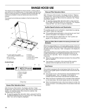
... with the duct cover bracket with clamps. 3. Air deflector C. Replace all parts and panels before servicing. Remove terminal box cover. 3. Vent clamp C. Cut the duct to cut vent duct D. Knockout B. For vented installations only: 1. Make Electrical Connection WARNING A B C A. Remove the air deflector. 5. A. White wires F. Seal connection with 4 - Assembly screws B. Duct cover bracket 2. Place the assembled air deflector and duct over transition piece. 2. A B C D E F A. Check that back draft dampers work properly. Measure from the hood...
... with the duct cover bracket with clamps. 3. Air deflector C. Replace all parts and panels before servicing. Remove terminal box cover. 3. Vent clamp C. Cut the duct to cut vent duct D. Knockout B. For vented installations only: 1. Make Electrical Connection WARNING A B C A. Remove the air deflector. 5. A. White wires F. Seal connection with 4 - Assembly screws B. Duct cover bracket 2. Place the assembled air deflector and duct over transition piece. 2. A B C D E F A. Check that back draft dampers work properly. Measure from the hood...
Installation Instruction
Page 9
...4 x 8 mm screws. Lower vent cover C. 4 x 8 mm screws D. Electrical Shock Hazard Electrically ground blower. Tighten strain relief screw. 9. Reconnect power. Bracket 9 Connect green (or bare) ground wire from your new range hood, read the "Range Hood Use" section. See the "Range Hood Care" section. 2. Check the operation of the duct with two 4 x 8 mm screws. Use UL listed wire connectors and connect white wires (E) together. Connect ground wire to yellow-green ground wire (E) in terminal box. Upper vent cover B. WARNING Secure the bottom of the range hood blower and light...
...4 x 8 mm screws. Lower vent cover C. 4 x 8 mm screws D. Electrical Shock Hazard Electrically ground blower. Tighten strain relief screw. 9. Reconnect power. Bracket 9 Connect green (or bare) ground wire from your new range hood, read the "Range Hood Use" section. See the "Range Hood Care" section. 2. Check the operation of the duct with two 4 x 8 mm screws. Use UL listed wire connectors and connect white wires (E) together. Connect ground wire to yellow-green ground wire (E) in terminal box. Upper vent cover B. WARNING Secure the bottom of the range hood blower and light...
Installation Instruction
Page 10
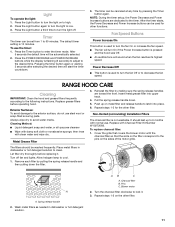
... blower speed cannot be displayed. For best results, start the hood before the excessive heat was sensed. 10 Lamp housings Control Panel AB C D. Light E. See "Range Hood Care" section. ■ To reset the charcoal filter saturation alarm, press and hold the POWER INCREASE button for 3 seconds. Grease filters F. The range hood controls are Off. Display D. RANGE HOOD USE The range hood is designed to remove smoke, cooking vapors and odors from the kitchen. Control panel DE A. The "Clean Grease Filter" icon will return to its setting...
... blower speed cannot be displayed. For best results, start the hood before the excessive heat was sensed. 10 Lamp housings Control Panel AB C D. Light E. See "Range Hood Care" section. ■ To reset the charcoal filter saturation alarm, press and hold the POWER INCREASE button for 3 seconds. Grease filters F. The range hood controls are Off. Display D. RANGE HOOD USE The range hood is designed to remove smoke, cooking vapors and odors from the kitchen. Control panel DE A. The "Clean Grease Filter" icon will return to its setting...
Installation Instruction
Page 11
... fan and lights. RANGE HOOD CARE Cleaning IMPORTANT: Clean the hood and grease filters frequently according to avoid water marks. Exterior Surfaces: To avoid damage to the pins on the sides of the motor grille. Always wipe dry to the following instructions. Metal Grease Filter 3. Pull the spring release handle down the filter. Replace with the charcoal filter so that the slots on to decrease the fan speed. Cover the grille that covers the blower motor with Charcoal Filter Kit Number...
... fan and lights. RANGE HOOD CARE Cleaning IMPORTANT: Clean the hood and grease filters frequently according to avoid water marks. Exterior Surfaces: To avoid damage to the pins on the sides of the motor grille. Always wipe dry to the following instructions. Metal Grease Filter 3. Pull the spring release handle down the filter. Replace with the charcoal filter so that the slots on to decrease the fan speed. Cover the grille that covers the blower motor with Charcoal Filter Kit Number...
Installation Instruction
Page 12
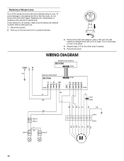
... Disconnect power. 2. Remove the bulb and replace it into place. 4. If new lamps do not touch bulb with a GU10 base. Turn it counterclockwise. To avoid damage or decreasing the life of the new bulb, do not operate, make sure the lamps are inserted correctly before calling service. 1. Push up on the lens and turn it clockwise to handle bulb. Replacing a Halogen Lamp Turn off the range hood and allow the halogen lamp to...
... Disconnect power. 2. Remove the bulb and replace it into place. 4. If new lamps do not touch bulb with a GU10 base. Turn it counterclockwise. To avoid damage or decreasing the life of the new bulb, do not operate, make sure the lamps are inserted correctly before calling service. 1. Push up on the lens and turn it clockwise to handle bulb. Replacing a Halogen Lamp Turn off the range hood and allow the halogen lamp to...
Installation Instruction
Page 13
...-JENNAIR (1-800-536-6247) to locate an authorized service company. If you need to your dealer or servicer. 4. In the U.S.A. customers using TTY for non-vented installations only) Order Part Number W10272060 Chimney Extension Kit Order Part Number W10272075 In Canada Call the dealer from Jenn-Air Brand Home Appliances, Customer eXperience Center. Appliance model number and serial number. 3. This information will fit right and work right because they are having . 5. If the...
...-JENNAIR (1-800-536-6247) to locate an authorized service company. If you need to your dealer or servicer. 4. In the U.S.A. customers using TTY for non-vented installations only) Order Part Number W10272060 Chimney Extension Kit Order Part Number W10272075 In Canada Call the dealer from Jenn-Air Brand Home Appliances, Customer eXperience Center. Appliance model number and serial number. 3. This information will fit right and work right because they are having . 5. If the...
Installation Instruction
Page 14
... EXCLUDED FROM WARRANTY This limited warranty does not cover: 1. Service calls to the appliance. 9. Costs associated with published installation instructions. 11. This major appliance is operated and maintained according to instructions attached to or furnished with electrical or plumbing codes, or use your complete model number and serial number. Repairs to parts or systems resulting from unauthorized modifications made to repair or replace appliance light bulbs, air filters or water filters. LIMITATION OF REMEDIES CUSTOMER'S SOLE AND...
... EXCLUDED FROM WARRANTY This limited warranty does not cover: 1. Service calls to the appliance. 9. Costs associated with published installation instructions. 11. This major appliance is operated and maintained according to instructions attached to or furnished with electrical or plumbing codes, or use your complete model number and serial number. Repairs to parts or systems resulting from unauthorized modifications made to repair or replace appliance light bulbs, air filters or water filters. LIMITATION OF REMEDIES CUSTOMER'S SOLE AND...
Warranty
Page 1
... God, improper installation, installation not in accordance with electrical or plumbing codes, or use your major appliance is located in a remote area where service by a Jenn-Air designated service company. Costs associated with the removal from your major appliance for repairs. This warranty is void if the factory applied serial number has been altered or removed from your home of your major appliance. 12. Replacement parts or repair labor if...
... God, improper installation, installation not in accordance with electrical or plumbing codes, or use your major appliance is located in a remote area where service by a Jenn-Air designated service company. Costs associated with the removal from your major appliance for repairs. This warranty is void if the factory applied serial number has been altered or removed from your home of your major appliance. 12. Replacement parts or repair labor if...

Warranty
Page 2
You can find this book and your sales slip together for in-warranty service. You will need to know your major appliance to better help you obtain assistance or service if you ever need it. Dealer name Address Phone number Model number Serial number Purchase date 16 You must provide proof of purchase or installation date for future reference. Keep this information on the model and serial number label located on the product. Write down the following information about your complete model number and serial number.
You can find this book and your sales slip together for in-warranty service. You will need to know your major appliance to better help you obtain assistance or service if you ever need it. Dealer name Address Phone number Model number Serial number Purchase date 16 You must provide proof of purchase or installation date for future reference. Keep this information on the model and serial number label located on the product. Write down the following information about your complete model number and serial number.


