

User Manual
Page 3
... channels to program frequencies and other various data. (Up to page 1. TM-281A: 144 MHz FM Transceiver TM-481A: 430 MHz FM Transceiver The frequency indication examples in this manual. For accessories supplied with alphanumeric display capability. • Free PC software (Memory Control Program) is available to the product specifications {pages 69, 70} for choosing this transceiver is pursuing "user friendliness". Thank you change the Menu No. Though user friendly, this Kenwood...
... channels to program frequencies and other various data. (Up to page 1. TM-281A: 144 MHz FM Transceiver TM-481A: 430 MHz FM Transceiver The frequency indication examples in this manual. For accessories supplied with alphanumeric display capability. • Free PC software (Memory Control Program) is available to the product specifications {pages 69, 70} for choosing this transceiver is pursuing "user friendliness". Thank you change the Menu No. Though user friendly, this Kenwood...

User Manual
Page 5
... MOBILE INSTALLATION 2 DC POWER CABLE CONNECTION 3 Mobile Operation 3 Fixed Station Operation 4 Replacing Fuses 5 ANTENNA CONNECTION 5 ACCESSORY CONNECTIONS 6 External Speaker 6 Microphone 6 PC Connection 7 CHAPTER 2 YOUR FIRST QSO CHAPTER 3 GETTING ACQUAINTED FRONT PANEL 9 DISPLAY 10 REAR PANEL 12 MICROPHONE 12 MIC KEYPAD DIRECT ENTRY 13 CHAPTER 4 OPERATING BASICS SWITCHING THE POWER ON/OFF 14 ADJUSTING THE VOLUME 14 ADJUSTING THE SQUELCH 14 TRANSMITTING 15 SELECTING AN OUTPUT POWER 15 SELECTING A FREQUENCY 15 ii VFO MODE 15 MHz MODE 16 DIRECT FREQUENCY ENTRY...
... MOBILE INSTALLATION 2 DC POWER CABLE CONNECTION 3 Mobile Operation 3 Fixed Station Operation 4 Replacing Fuses 5 ANTENNA CONNECTION 5 ACCESSORY CONNECTIONS 6 External Speaker 6 Microphone 6 PC Connection 7 CHAPTER 2 YOUR FIRST QSO CHAPTER 3 GETTING ACQUAINTED FRONT PANEL 9 DISPLAY 10 REAR PANEL 12 MICROPHONE 12 MIC KEYPAD DIRECT ENTRY 13 CHAPTER 4 OPERATING BASICS SWITCHING THE POWER ON/OFF 14 ADJUSTING THE VOLUME 14 ADJUSTING THE SQUELCH 14 TRANSMITTING 15 SELECTING AN OUTPUT POWER 15 SELECTING A FREQUENCY 15 ii VFO MODE 15 MHz MODE 16 DIRECT FREQUENCY ENTRY...
User Manual
Page 8
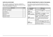
..., identify the items listed in turn the transceiver power ON by pressing [ ] (Power Switch). 1 Press KEY1 momentarily, release KEY1, then press KEY2. If there are more than 2 keys, press and hold KEY, then turn until the final key has been pressed. What to simplify instructions and avoid unnecessary repetition. Accessory Qty Microphone (DTMF Mic) 1 DC power cable (Blade) 1 Fuse (Blade) 1 Mounting bracket 1 Screw set 1 Microphone hanger 1 Instruction manual 1 WRITING CONVENTIONS FOLLOWED...
..., identify the items listed in turn the transceiver power ON by pressing [ ] (Power Switch). 1 Press KEY1 momentarily, release KEY1, then press KEY2. If there are more than 2 keys, press and hold KEY, then turn until the final key has been pressed. What to simplify instructions and avoid unnecessary repetition. Accessory Qty Microphone (DTMF Mic) 1 DC power cable (Blade) 1 Fuse (Blade) 1 Mounting bracket 1 Screw set 1 Microphone hanger 1 Instruction manual 1 WRITING CONVENTIONS FOLLOWED...

User Manual
Page 12
... installed fuses continue to start the vehicle. Fuse Location Transceiver Supplied Accessory DC Power Cable Fuse Current Rating 15 A 20 A Only use the transceiver for a long period when the vehicle battery is not fully charged, or when the engine is resolved, replace the fuse. ANTENNA CONNECTION Before operating, install an efficient, well-tuned antenna. Always connect the antenna to the transceiver before transmitting. ◆ All fixed stations should be damaged. Antenna connector To antenna...
... installed fuses continue to start the vehicle. Fuse Location Transceiver Supplied Accessory DC Power Cable Fuse Current Rating 15 A 20 A Only use the transceiver for a long period when the vehicle battery is not fully charged, or when the engine is resolved, replace the fuse. ANTENNA CONNECTION Before operating, install an efficient, well-tuned antenna. Always connect the antenna to the transceiver before transmitting. ◆ All fixed stations should be damaged. Antenna connector To antenna...
User Manual
Page 14
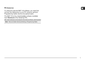
The MCP-1A is free downloadable software available from Kenwood at the following URL: http://www.kenwood.com/i/products/info/amateur/software_download.html Note: Ask your PC using an optional Programming Cable (via the microphone jack). PC CONNECTION To utilize the optional MCP-1A software, you must first connect the transceiver to your dealer about purchasing a Programming Cable. 1 7
The MCP-1A is free downloadable software available from Kenwood at the following URL: http://www.kenwood.com/i/products/info/amateur/software_download.html Note: Ask your PC using an optional Programming Cable (via the microphone jack). PC CONNECTION To utilize the optional MCP-1A software, you must first connect the transceiver to your dealer about purchasing a Programming Cable. 1 7

User Manual
Page 16
... switch the transceiver power ON or OFF {page 14}. when in Memory Recall Mode to adjust the level of the front panel controls. Press and hold for 1 second while in Menu Mode {page 18}. • Scan direction while scanning {pages 27, 37, 45, 47}. w MENU button/ Tuning control Press to recall the Call Channel {page 35}. Turn to begin Program Scan {page 38}. 9 r VFO key Press to enter Menu Mode...
... switch the transceiver power ON or OFF {page 14}. when in Memory Recall Mode to adjust the level of the front panel controls. Press and hold for 1 second while in Menu Mode {page 18}. • Scan direction while scanning {pages 27, 37, 45, 47}. w MENU button/ Tuning control Press to recall the Call Channel {page 35}. Turn to begin Program Scan {page 38}. 9 r VFO key Press to enter Menu Mode...

User Manual
Page 19
... the operating frequency, Memory Channel number, Menu Number, etc. Release to transmit . 12 When making test transmissions, connect a dummy load in place of 50 Ω. w DWN/ key Press to transmit. MICROPHONE : @ . ; =: B > 2 DTMF Microphone Microphone (KMC-30) q PTT (Push-to-Talk) switch Press and hold Mic [PTT], then press [UP/ ] to receive. REAR PANEL : @ . 3 q Antenna connector Connect an external antenna {page 5} here. This jack accepts a 3.5 mm (1/8") mono (2-conductor) plug. e SP (speaker) jack If desired, connect...
... the operating frequency, Memory Channel number, Menu Number, etc. Release to transmit . 12 When making test transmissions, connect a dummy load in place of 50 Ω. w DWN/ key Press to transmit. MICROPHONE : @ . ; =: B > 2 DTMF Microphone Microphone (KMC-30) q PTT (Push-to-Talk) switch Press and hold Mic [PTT], then press [UP/ ] to receive. REAR PANEL : @ . 3 q Antenna connector Connect an external antenna {page 5} here. This jack accepts a 3.5 mm (1/8") mono (2-conductor) plug. e SP (speaker) jack If desired, connect...

User Manual
Page 22
...; " " and the RF Power meter appears. SELECTING AN OUTPUT POWER You can configure different power levels for an extended period of time. default) or "L" (low) power. 3 Press [MENU] to store the setting or any other key to cancel. 4 Press any key other than the time specified in your mouth, then press and hold Mic [UP]/[DWN] to decrease the frequency, or use Mic [UP]/[DWN]. • Press...
...; " " and the RF Power meter appears. SELECTING AN OUTPUT POWER You can configure different power levels for an extended period of time. default) or "L" (low) power. 3 Press [MENU] to store the setting or any other key to cancel. 4 Press any key other than the time specified in your mouth, then press and hold Mic [UP]/[DWN] to decrease the frequency, or use Mic [UP]/[DWN]. • Press...
User Manual
Page 26
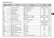
... TXP 2 Tone frequency 3 CTCSS frequency 4 DCS code 5 Shift direction 6 Transmission power P.VFO 7 Programmable VFO SSQ SQH 8 S-Meter squelch 9 Squelch hang time OFFSET 10 Repeater offset frequency ARO PRI SCAN L.OUT M.CH M.NAME MDF APO 11 Automatic Repeater Offset 12 Priority Scan 13 Scan Resume method 14 Memory Channel Lockout 15 Memory Channel capacity 16 Memory Name 17 Memory Name/ Frequency display 18 Automatic Power-off Selections 2.5(TM-281A Only)/5 / 6.25...
... TXP 2 Tone frequency 3 CTCSS frequency 4 DCS code 5 Shift direction 6 Transmission power P.VFO 7 Programmable VFO SSQ SQH 8 S-Meter squelch 9 Squelch hang time OFFSET 10 Repeater offset frequency ARO PRI SCAN L.OUT M.CH M.NAME MDF APO 11 Automatic Repeater Offset 12 Priority Scan 13 Scan Resume method 14 Memory Channel Lockout 15 Memory Channel capacity 16 Memory Name 17 Memory Name/ Frequency display 18 Automatic Power-off Selections 2.5(TM-281A Only)/5 / 6.25...

User Manual
Page 34
... key to exit the Tone Frequency ID Scan. • Turn the Tuning control while the identified tone 6 frequency is blinking to resume scanning. 4 Press any key other station's uplink signal to detect the repeater access tone. ◆ The transceiver continues to check the Weather Alert Channel and Priority Channel during Tone Frequency ID Scan, the signal is switched OFF. ◆ ASC causes received audio to be activated while operating in Simplex Mode...
... key to exit the Tone Frequency ID Scan. • Turn the Tuning control while the identified tone 6 frequency is blinking to resume scanning. 4 Press any key other station's uplink signal to detect the repeater access tone. ◆ The transceiver continues to check the Weather Alert Channel and Priority Channel during Tone Frequency ID Scan, the signal is switched OFF. ◆ ASC causes received audio to be activated while operating in Simplex Mode...

User Manual
Page 37
... Channel. RECALLING A MEMORY CHANNEL USING THE TUNING CONTROL 1 Press [MR] to enter Memory Recall mode. • The Memory Channel last used is recalled. 2 Turn the Tuning control to store the data. 5 Press [MR] (1s). • The transmission frequency is stored in which you recall an odd-split Memory Channel, "+" and "-" appear on those repeaters without programming the offset frequency and direction. 7 1 Store the desired reception frequency...
... Channel. RECALLING A MEMORY CHANNEL USING THE TUNING CONTROL 1 Press [MR] to enter Memory Recall mode. • The Memory Channel last used is recalled. 2 Turn the Tuning control to store the data. 5 Press [MR] (1s). • The transmission frequency is stored in which you recall an odd-split Memory Channel, "+" and "-" appear on those repeaters without programming the offset frequency and direction. 7 1 Store the desired reception frequency...
User Manual
Page 42
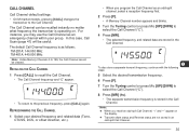
... transmission frequency is operating on the display. ◆ Transmit offset status and Reverse status are stored in the Call Channel. 7 To also store a separate transmit frequency, continue with the following steps: 5 Select the desired transmission frequency. 6 Press [F]. 7 Turn the Tuning control or press Mic [UP]/[DWN] to 199, the Call Channel cannot be useful. CALL CHANNEL Call Channel default settings: • On M market models, pressing [CALL] changes...
... transmission frequency is operating on the display. ◆ Transmit offset status and Reverse status are stored in the Call Channel. 7 To also store a separate transmit frequency, continue with the following steps: 5 Select the desired transmission frequency. 6 Press [F]. 7 Turn the Tuning control or press Mic [UP]/[DWN] to 199, the Call Channel cannot be useful. CALL CHANNEL Call Channel default settings: • On M market models, pressing [CALL] changes...

User Manual
Page 44
... Band Scan Scans the entire band of the frequency you can change the scan frequency direction by turning the Tuning control or using the Mic [UP]/[DWN] keys. ◆ Starting scan switches OFF the Automatic Simplex Check (ASC) {page 26}. ◆ Adjust the Squelch level before using Scan {page 14}. Scans Memory Channels in Group Scan groups of scans. SCAN Scan is activated, the transceiver stops at a busy frequency and decodes the CTCSS tone or DCS code. Scans the Call Channel...
... Band Scan Scans the entire band of the frequency you can change the scan frequency direction by turning the Tuning control or using the Mic [UP]/[DWN] keys. ◆ Starting scan switches OFF the Automatic Simplex Check (ASC) {page 26}. ◆ Adjust the Squelch level before using Scan {page 14}. Scans Memory Channels in Group Scan groups of scans. SCAN Scan is activated, the transceiver stops at a busy frequency and decodes the CTCSS tone or DCS code. Scans the Call Channel...

User Manual
Page 45
... to receiver VFO frequency range in the specifications {page 70}.) When the current VFO receive frequency is outside the Program Scan frequency range {below}, the transceiver scans the entire frequency range available for specifying the start and end frequencies. NORMAL SCAN When you are operating the transceiver in VFO Mode, 3 types of scanning are 3 memory channel pairs (L0/U0 ~ L2/U2) available for the current VFO. 1 Press [VFO] and turn the Tuning control...
... to receiver VFO frequency range in the specifications {page 70}.) When the current VFO receive frequency is outside the Program Scan frequency range {below}, the transceiver scans the entire frequency range available for specifying the start and end frequencies. NORMAL SCAN When you are operating the transceiver in VFO Mode, 3 types of scanning are 3 memory channel pairs (L0/U0 ~ L2/U2) available for the current VFO. 1 Press [VFO] and turn the Tuning control...

User Manual
Page 47
... 40 When Menu No. 15 (M.CH) is paused, the Channel number blinks. Note: ◆ You must have stored frequencies. 1 Press [MR] (1s). • Scan starts from the selected Memory Channel number and ascends up through the channel numbers (default). • To reverse the scan direction, turn the Tuning control or press Mic [UP]/[DWN] to 100, the transceiver uses 5 groups of 20 channels. GROUP SCAN The transceiver scans Memory Channels in CH Display Mode.
... 40 When Menu No. 15 (M.CH) is paused, the Channel number blinks. Note: ◆ You must have stored frequencies. 1 Press [MR] (1s). • Scan starts from the selected Memory Channel number and ascends up through the channel numbers (default). • To reverse the scan direction, turn the Tuning control or press Mic [UP]/[DWN] to 100, the transceiver uses 5 groups of 20 channels. GROUP SCAN The transceiver scans Memory Channels in CH Display Mode.

User Manual
Page 53
... exit the CTCSS Frequency ID Scan. • Turn the Tuning control or press Mic [UP]/[DWN] while the identified frequency is blinking to resume scanning. 4 Press any key other than [MENU] to exit Menu Mode. 9 Note: ◆ CTCSS turns ON automatically when performing CTCSS Frequency ID Scan, even if the current frequency is not set with CTCSS. ◆ Received signals are monitored through the speaker while scanning is in the table...
... exit the CTCSS Frequency ID Scan. • Turn the Tuning control or press Mic [UP]/[DWN] while the identified frequency is blinking to resume scanning. 4 Press any key other than [MENU] to exit Menu Mode. 9 Note: ◆ CTCSS turns ON automatically when performing CTCSS Frequency ID Scan, even if the current frequency is not set with CTCSS. ◆ Received signals are monitored through the speaker while scanning is in the table...

User Manual
Page 64
... function from the list provided below. 3 Press [MENU] to store the setting or any other key to cancel. 4 Press any key other than [MENU] to exit Menu Mode. When programming the PF keys in order to program the microphone keys. 1 Press [F], [MENU] and turn the Tuning control to select one of Menu No. 35 to Menu No. 38 (PF1 ~ PF4). 2 Press [MENU] and turn the transceiver power ON. Microphone keys PF/D, MR/C, VFO...
... function from the list provided below. 3 Press [MENU] to store the setting or any other key to cancel. 4 Press any key other than [MENU] to exit Menu Mode. When programming the PF keys in order to program the microphone keys. 1 Press [F], [MENU] and turn the Tuning control to select one of Menu No. 35 to Menu No. 38 (PF1 ~ PF4). 2 Press [MENU] and turn the transceiver power ON. Microphone keys PF/D, MR/C, VFO...
User Manual
Page 66
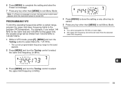
... MHz for the band appears. 2 Press [MENU] and turn the Tuning control to exit Menu Mode. Note: If a Power-on message. 7 Press any key other than [MENU] to the program VFO parameters. PROGRAMMABLE VFO To limit the operating frequencies within a certain range, program the upper and lower frequency limits to exit Menu Mode. 6 Press [MENU] to complete the setting and store the Power-on message is not set lower than the...
... MHz for the band appears. 2 Press [MENU] and turn the Tuning control to exit Menu Mode. Note: If a Power-on message. 7 Press any key other than [MENU] to the program VFO parameters. PROGRAMMABLE VFO To limit the operating frequencies within a certain range, program the upper and lower frequency limits to exit Menu Mode. 6 Press [MENU] to complete the setting and store the Power-on message is not set lower than the...
User Manual
Page 74
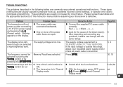
... was connected backwards. 2 One or more of this range, adjust your transceiver is 3, 4 13.8 V DC ±15% (11.7 V to 15.8 V DC). The transceiver will not power up , accidental incorrect control settings, or operator error due to incomplete programming. The supply voltage requirement is defective. TROUBLESHOOTING The problems described in Channel 2 With the transceiver power OFF, press 36 Display mode. [ ] (Power)+[REV] to exit Channel Display mode. 14 67 Please review these...
... was connected backwards. 2 One or more of this range, adjust your transceiver is 3, 4 13.8 V DC ±15% (11.7 V to 15.8 V DC). The transceiver will not power up , accidental incorrect control settings, or operator error due to incomplete programming. The supply voltage requirement is defective. TROUBLESHOOTING The problems described in Channel 2 With the transceiver power OFF, press 36 Display mode. [ ] (Power)+[REV] to exit Channel Display mode. 14 67 Please review these...

User Manual
Page 78
... Fuses, Replacing 5 Group Scan 40 Installation 2 Accessory Connections ........ 6 Antenna Connection 5 DC Power Cable Connection, Fixed Station 4 DC Power Cable Connection, Mobile 3 PC Connection 7 Keypad Direct Entry 13 Keys and Controls 9 Lock Function 56 Maintenance 64 Manual Dialing 48 Memory Channels Clearing 31 Lockout 42 Naming 32 Recalling 30 Storing, Odd-split 30 Storing, Simplex 29 Transfer to VFO 33 Menu Access 18 Function List 19 MHz Mode 16 MHz Scan 39 Microphone Control 61 Lock 62 PF Keys 57 Narrow Band...
... Fuses, Replacing 5 Group Scan 40 Installation 2 Accessory Connections ........ 6 Antenna Connection 5 DC Power Cable Connection, Fixed Station 4 DC Power Cable Connection, Mobile 3 PC Connection 7 Keypad Direct Entry 13 Keys and Controls 9 Lock Function 56 Maintenance 64 Manual Dialing 48 Memory Channels Clearing 31 Lockout 42 Naming 32 Recalling 30 Storing, Odd-split 30 Storing, Simplex 29 Transfer to VFO 33 Menu Access 18 Function List 19 MHz Mode 16 MHz Scan 39 Microphone Control 61 Lock 62 PF Keys 57 Narrow Band...


