
Operation Manual
Page 3
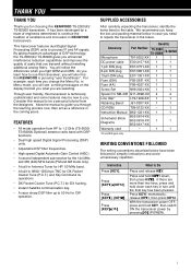
... messages on the display that tell you what you are selecting. FEATURES • All mode operation from the designers. Accessory Quantity Part Number TS-2000 TS-2000X TS-B2000 Microphone T91-0352-XX 1 1 DC power cable E30-3157-XX 1 1 7-pin DIN plug E07-0751-XX 1 1 8-pin DIN plug E07-0851-XX 1 1 13-pin DIN plug E07-1351-XX 1 1 Fuse (25A) F05-2531-XX 1 1 Fuse (4A) F06-4027-XX 1 1 Screw Set N99-2024...
... messages on the display that tell you what you are selecting. FEATURES • All mode operation from the designers. Accessory Quantity Part Number TS-2000 TS-2000X TS-B2000 Microphone T91-0352-XX 1 1 DC power cable E30-3157-XX 1 1 7-pin DIN plug E07-0751-XX 1 1 8-pin DIN plug E07-0851-XX 1 1 13-pin DIN plug E07-1351-XX 1 1 Fuse (25A) F05-2531-XX 1 1 Fuse (4A) F06-4027-XX 1 1 Screw Set N99-2024...
Operation Manual
Page 6
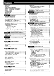
... POWER SUPPLY CONNECTION 2 UTILIZING THE BAIL (TS-2000 (X) ONLY 2 REPLACING FUSES 2 ACCESSORY CONNECTIONS 3 FRONT PANEL 3 Headphones (PHONES 3 Microphone (MIC 3 REAR PANEL 3 External Speakers (EXT.SP1/ EXT.SP2) ......... 3 Keys for CW (PADDLE and KEY 3 CHAPTER 2 YOUR FIRST QSO (HF/ 50MHz band) RECEIVING 4 TRANSMITTING 5 CHAPTER 3 YOUR FIRST QSO (VHF/ UHF band) RECEIVING 6 TRANSMITTING 7 CHAPTER 4 GETTING ACQUAINTED FRONT PANEL 8 REAR PANEL 13 DISPLAY 14 MICROPHONE 17 CHAPTER 5 OPERATING BASICS SWITCHING POWER ON/OFF 18 ADJUSTING VOLUME 18 AUDIO FREQUENCY (AF) GAIN 18 RADIO...
... POWER SUPPLY CONNECTION 2 UTILIZING THE BAIL (TS-2000 (X) ONLY 2 REPLACING FUSES 2 ACCESSORY CONNECTIONS 3 FRONT PANEL 3 Headphones (PHONES 3 Microphone (MIC 3 REAR PANEL 3 External Speakers (EXT.SP1/ EXT.SP2) ......... 3 Keys for CW (PADDLE and KEY 3 CHAPTER 2 YOUR FIRST QSO (HF/ 50MHz band) RECEIVING 4 TRANSMITTING 5 CHAPTER 3 YOUR FIRST QSO (VHF/ UHF band) RECEIVING 6 TRANSMITTING 7 CHAPTER 4 GETTING ACQUAINTED FRONT PANEL 8 REAR PANEL 13 DISPLAY 14 MICROPHONE 17 CHAPTER 5 OPERATING BASICS SWITCHING POWER ON/OFF 18 ADJUSTING VOLUME 18 AUDIO FREQUENCY (AF) GAIN 18 RADIO...
Operation Manual
Page 8
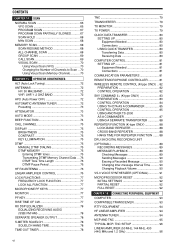
... EQUALIZING RECEIVING AUDIO (SSB/ FM/ AM 78 SEPARATE SPEAKER OUTPUT 78 S-METER SQUELCH 78 SQUELCH HANG TIME 78 TIME-OUT TIMER 78 vi TNC 79 TRANSVERTER 79 TX MONITOR 79 TX POWER 79 QUICK DATA TRANSFER 80 SETTING UP 80 Equipment Needed 80 Connections 80 USING QUICK TRANSFER 80 Transferring Data 80 Receiving Data 80 COMPUTER CONTROL 81 SETTING UP 81 Equipment Needed 81 Connections 81 COMMUNICATION PARAMETERS 81 REMOTE MICROPHONE CONTROLLER 81 WIRELESS REMOTE CONTROL (K-type ONLY) .. 82 PREPARATION 82 CONTROL OPERATION...
... EQUALIZING RECEIVING AUDIO (SSB/ FM/ AM 78 SEPARATE SPEAKER OUTPUT 78 S-METER SQUELCH 78 SQUELCH HANG TIME 78 TIME-OUT TIMER 78 vi TNC 79 TRANSVERTER 79 TX MONITOR 79 TX POWER 79 QUICK DATA TRANSFER 80 SETTING UP 80 Equipment Needed 80 Connections 80 USING QUICK TRANSFER 80 Transferring Data 80 Receiving Data 80 COMPUTER CONTROL 81 SETTING UP 81 Equipment Needed 81 Connections 81 COMMUNICATION PARAMETERS 81 REMOTE MICROPHONE CONTROLLER 81 WIRELESS REMOTE CONTROL (K-type ONLY) .. 82 PREPARATION 82 CONTROL OPERATION...

Operation Manual
Page 11
... your signal is 1.5:1 or less. Connect all accessories to prevent such dangers as stereo receivers and televisions. Reports that your property {page 1}. Accessories include the following: • Microphone • Headphones • Antenna Tuner • External Speaker • CW Key • RTTY Equipment • Computer • Linear Amplifier • TNC/ Multimode • Remote Panel Communications Processor ANTENNA CONNECTION An antenna system consists of the coaxial cable and antenna...
... your signal is 1.5:1 or less. Connect all accessories to prevent such dangers as stereo receivers and televisions. Reports that your property {page 1}. Accessories include the following: • Microphone • Headphones • Antenna Tuner • External Speaker • CW Key • RTTY Equipment • Computer • Linear Amplifier • TNC/ Multimode • Remote Panel Communications Processor ANTENNA CONNECTION An antenna system consists of the coaxial cable and antenna...
Operation Manual
Page 12
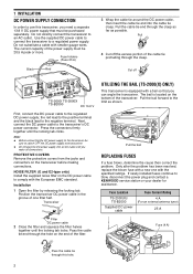
... power plug and contact a KENWOOD service station or your dealer for assistance. If newly installed fuses continue to the limit as possible. Pull 4 Cut off TS-2000/ TS-2000X TS-B2000 DC 13.8 V First, connect the DC power cable to an AC outlet. Press the connectors firmly together until the locking tab locks. Fuse (4 A) Pass the cable tie through the clasp. Use the supplied DC power cable to connect the transceiver to comply with a new...
... power plug and contact a KENWOOD service station or your dealer for assistance. If newly installed fuses continue to the limit as possible. Pull 4 Cut off TS-2000/ TS-2000X TS-B2000 DC 13.8 V First, connect the DC power cable to an AC outlet. Press the connectors firmly together until the locking tab locks. Fuse (4 A) Pass the cable tie through the clasp. Use the supplied DC power cable to connect the transceiver to comply with a new...
Operation Manual
Page 13
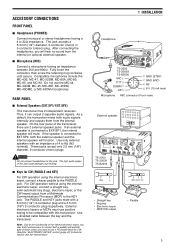
.... 1 INSTALLATION Headphone TS-2000 TS-2000X TS-B2000 MIC q PTT w DOWN e UP r i GND (STBY) u GND (MIC) y NC t 8 V (10 mA max) Microphone MIC connector (Front view) External speaker TS-2000 TS-2000X TS-B2000 GND + GND dash dot • Straight key • Bug key • Electronic keyer • MCP CW output • Paddle 3 This jack accepts a 6.3 mm (1/4") diameter, 2-conductor (mono) or 3-conductor (stereo) plug. Read the "ELECTRONIC KEYER" section {page 42} to be compatible with...
.... 1 INSTALLATION Headphone TS-2000 TS-2000X TS-B2000 MIC q PTT w DOWN e UP r i GND (STBY) u GND (MIC) y NC t 8 V (10 mA max) Microphone MIC connector (Front view) External speaker TS-2000 TS-2000X TS-B2000 GND + GND dash dot • Straight key • Bug key • Electronic keyer • MCP CW output • Paddle 3 This jack accepts a 6.3 mm (1/4") diameter, 2-conductor (mono) or 3-conductor (stereo) plug. Read the "ELECTRONIC KEYER" section {page 42} to be compatible with...

Operation Manual
Page 18
... either Antenna 1 or Antenna 2 for the HF/ 50 MHz band {page 72}. Press [FUNC], [AT/ ANT1/2] to adjust the Speech Processor input level. Inserting a plug into the jack automatically mutes the audio from the speaker {pages 3, 78}. !0 MIC connector Connect a compatible microphone to switch the Speech Processor for VOX operation. o PHONES jack Connect a set of headphones to this connector, then securely screw down the connector locking ring {page 3}. !1 N.R./ LEVEL key Press to switch the Frequency Lock function...
... either Antenna 1 or Antenna 2 for the HF/ 50 MHz band {page 72}. Press [FUNC], [AT/ ANT1/2] to adjust the Speech Processor input level. Inserting a plug into the jack automatically mutes the audio from the speaker {pages 3, 78}. !0 MIC connector Connect a compatible microphone to switch the Speech Processor for VOX operation. o PHONES jack Connect a set of headphones to this connector, then securely screw down the connector locking ring {page 3}. !1 N.R./ LEVEL key Press to switch the Frequency Lock function...

Operation Manual
Page 22
... band LED Lights green while the sub-receiver's squelch is set to the manual frequency adjustment mode {page 56}. $6 MAIN RF GAIN control Turn to adjust the radio frequency gain for the low cut -off DSP filter frequency or the filter bandwidth (CW/ FSK). 4 GETTING ACQUAINTED 54 PF F LOCK A ATT LEVEL VOX PRE LEVEL PROC SEND ANT1/2 AT PHONES LEVEL LEVEL MIC MANUAL N.R. Also used for selecting Menu numbers when accessing the Menu mode...
... band LED Lights green while the sub-receiver's squelch is set to the manual frequency adjustment mode {page 56}. $6 MAIN RF GAIN control Turn to adjust the radio frequency gain for the low cut -off DSP filter frequency or the filter bandwidth (CW/ FSK). 4 GETTING ACQUAINTED 54 PF F LOCK A ATT LEVEL VOX PRE LEVEL PROC SEND ANT1/2 AT PHONES LEVEL LEVEL MIC MANUAL N.R. Also used for selecting Menu numbers when accessing the Menu mode...

Operation Manual
Page 30
... microphone in FM mode. When operating from 5 W to switch the Break-in "TRANSMISSION" {pages 28, 29, 30}. CAR MIC TX MONI PWR DELAY KEY PF F LOCK A ATT LEVEL VOX PRE LEVEL PROC SEND ANT1/2 AT PHONES LEVEL LEVEL MIC MANUAL N.R. Note: When using AM, CW, or FSK mode, you more operating time before a charge is low in FM mode, select "HIGH" for the microphone gain. For the adjustment...
... microphone in FM mode. When operating from 5 W to switch the Break-in "TRANSMISSION" {pages 28, 29, 30}. CAR MIC TX MONI PWR DELAY KEY PF F LOCK A ATT LEVEL VOX PRE LEVEL PROC SEND ANT1/2 AT PHONES LEVEL LEVEL MIC MANUAL N.R. Note: When using AM, CW, or FSK mode, you more operating time before a charge is low in FM mode, select "HIGH" for the microphone gain. For the adjustment...

Operation Manual
Page 37
...PF key Microphone PF1 (CALL) key Microphone PF2 (VFO) key Microphone PF3 (MR) key Microphone PF4 (PF) key POWER CONTROL Fine transmit power tuning POWER ON/ OFF APO (Auto Power Off) function REMOTE CONTROL Enable Mic remote control Display mode for RC-2000 RC-2000 font in easy operation mode RC-2000 panel/ TS-2000(X) dot-matrix display contrast REPEATER Acknowledgement signal in external remote control mode External remote control Remote control ID code Repeater mode select Repeater TX hold SCAN Program scan hold Program scan partially slowed Slow down frequency range for the Program scan Scan...
...PF key Microphone PF1 (CALL) key Microphone PF2 (VFO) key Microphone PF3 (MR) key Microphone PF4 (PF) key POWER CONTROL Fine transmit power tuning POWER ON/ OFF APO (Auto Power Off) function REMOTE CONTROL Enable Mic remote control Display mode for RC-2000 RC-2000 font in easy operation mode RC-2000 panel/ TS-2000(X) dot-matrix display contrast REPEATER Acknowledgement signal in external remote control mode External remote control Remote control ID code Repeater mode select Repeater TX hold SCAN Program scan hold Program scan partially slowed Slow down frequency range for the Program scan Scan...

Operation Manual
Page 42
... station. Generally they operate at higher ERP (Effective Radiated Power) than FM communications without using FM mode, you cannot change the offset direction. ■ Selecting an Offset Frequency To access a repeater which requires an odd-split frequency pair, change the default (-7.6 MHz or -6.0 MHz). 32 For further information, including repeater frequencies, consult your signal to bring the transmit frequency within the band limits: • Move the receive frequency further...
... station. Generally they operate at higher ERP (Effective Radiated Power) than FM communications without using FM mode, you cannot change the offset direction. ■ Selecting an Offset Frequency To access a repeater which requires an odd-split frequency pair, change the default (-7.6 MHz or -6.0 MHz). 32 For further information, including repeater frequencies, consult your signal to bring the transmit frequency within the band limits: • Move the receive frequency further...

Operation Manual
Page 52
...-in steps of the time period that you have selected has passed. 6 Press [FUNC], [KEY/ DELAY] again. The transceiver then returns to complete the setting. The built-in order to send error-free CW that you to transmit CW without manually switching between transmit and receive modes. Use Menu No. 33 to select AUTO, or 2.5 ~ 4.0 (in : When the key contacts open , the transceiver...
...-in steps of the time period that you have selected has passed. 6 Press [FUNC], [KEY/ DELAY] again. The transceiver then returns to complete the setting. The built-in order to send error-free CW that you to transmit CW without manually switching between transmit and receive modes. Use Menu No. 33 to select AUTO, or 2.5 ~ 4.0 (in : When the key contacts open , the transceiver...
Operation Manual
Page 63
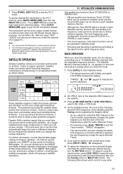
... receive change the uplink (TX) frequency so that allows azimuth and elevation control, plus a high-gain directional antenna. Press [SET/ P.C.T.] to tune the main band to quit the DX information display. Even so, many hams have been successfully using this function. ◆ The DX Packet Cluster data in each Satellite memory channel, the sub-audible tone frequency/ code cannot be set to limited memory capacity. Press QUICK...
... receive change the uplink (TX) frequency so that allows azimuth and elevation control, plus a high-gain directional antenna. Press [SET/ P.C.T.] to tune the main band to quit the DX information display. Even so, many hams have been successfully using this function. ◆ The DX Packet Cluster data in each Satellite memory channel, the sub-audible tone frequency/ code cannot be set to limited memory capacity. Press QUICK...

Operation Manual
Page 69
...; This frequency and mode will be changed while using a frequency that was last selected appears. • To exit Memory Scroll mode and abort the storage process, press [CLR]. 7 Turn the MULTI/ CH control, or press Mic [UP]/ [DWN] to store the data. • The previous data stored in a memory channel: Memory Recall and Memory Scroll. You can also select a channel by entering a 3-digit number, such...
...; This frequency and mode will be changed while using a frequency that was last selected appears. • To exit Memory Scroll mode and abort the storage process, press [CLR]. 7 Turn the MULTI/ CH control, or press Mic [UP]/ [DWN] to store the data. • The previous data stored in a memory channel: Memory Recall and Memory Scroll. You can also select a channel by entering a 3-digit number, such...

Operation Manual
Page 77
... a channel where a signal is displayed on the sub-receiver and perform the Program Scan, the sub-receiver automatically skips the memory channels that you selected with the channel numbers, Scan starts with the start frequency stored in the smallest channel number. ◆ The operating mode can be changed mode. ◆ When the current Scan range is outside all the ranges that cannot be within one of the Menu No. 04 setting. ◆ You cannot change the scan...
... a channel where a signal is displayed on the sub-receiver and perform the Program Scan, the sub-receiver automatically skips the memory channels that you selected with the channel numbers, Scan starts with the start frequency stored in the smallest channel number. ◆ The operating mode can be changed mode. ◆ When the current Scan range is outside all the ranges that cannot be within one of the Menu No. 04 setting. ◆ You cannot change the scan...

Operation Manual
Page 87
... to disable the squelch function temporarily. The default is ON. The 4, 2 or 1 ms settings are receiving while the squelch function is ON, weak signals become intermittent. Note: ◆ After activating Frequency Lock, the MULTI/ CH control and [+]/ [-] are disabled by Frequency Lock: Tuning control A=B MULTI/ CH control CALL A/B CLR CW/ FSK DISP ENT FM/ AM MsVFO SATL LSB/ USB/AUTO QUICK MEMO [M.IN] SCAN/ SG.SEL M.IN...
... to disable the squelch function temporarily. The default is ON. The 4, 2 or 1 ms settings are receiving while the squelch function is ON, weak signals become intermittent. Note: ◆ After activating Frequency Lock, the MULTI/ CH control and [+]/ [-] are disabled by Frequency Lock: Tuning control A=B MULTI/ CH control CALL A/B CLR CW/ FSK DISP ENT FM/ AM MsVFO SATL LSB/ USB/AUTO QUICK MEMO [M.IN] SCAN/ SG.SEL M.IN...
Operation Manual
Page 89
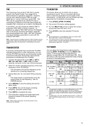
... COM port on the main transceiver of the transmission. In FSK mode, you can adjust the transmission output power by pressing [+]. • The output power is automatically set to monitor the on the same band. Note: When using the numeric keys. 6 Press [ENT] to check the modulation sound quality of the TS-2000(X). • The transverter will use this menu is usually used for each operating band. ◆...
... COM port on the main transceiver of the transmission. In FSK mode, you can adjust the transmission output power by pressing [+]. • The output power is automatically set to monitor the on the same band. Note: When using the numeric keys. 6 Press [ENT] to check the modulation sound quality of the TS-2000(X). • The transverter will use this menu is usually used for each operating band. ◆...
Operation Manual
Page 92
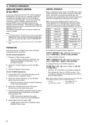
... the secret number will be used as shown in the table on the 440 MHz band. 3 Enter the Remote Control mode. Note: If you are using FM mode. If you do not add "A#" on the end, you can select a separate tone frequency for control code strings. You can skip sending "AXXX#" next time; 15 OPERATOR CONVENIENCES WIRELESS REMOTE CONTROL (K-type ONLY) If you have a remote control function, but...
... the secret number will be used as shown in the table on the 440 MHz band. 3 Enter the Remote Control mode. Note: If you are using FM mode. If you do not add "A#" on the end, you can select a separate tone frequency for control code strings. You can skip sending "AXXX#" next time; 15 OPERATOR CONVENIENCES WIRELESS REMOTE CONTROL (K-type ONLY) If you have a remote control function, but...

Operation Manual
Page 110
... set. After understanding what digits appear on the data will be lost , do a Partial Reset. SSB audio quality is 1 The wrong operation mode is not connected 3 Confirm the connections to 77 switch the function OFF. 3 Review "MICROPROCESSOR 92 RESET". low audio frequencies 2 The LO/ WIDTH control or 2 Turn the LO/ WIDTH control 55 are usually not caused by circuit failure. Note: Placing a powered portable transceiver near this manual. power supply and Red...
... set. After understanding what digits appear on the data will be lost , do a Partial Reset. SSB audio quality is 1 The wrong operation mode is not connected 3 Confirm the connections to 77 switch the function OFF. 3 Review "MICROPROCESSOR 92 RESET". low audio frequencies 2 The LO/ WIDTH control or 2 Turn the LO/ WIDTH control 55 are usually not caused by circuit failure. Note: Placing a powered portable transceiver near this manual. power supply and Red...

Operation Manual
Page 152
..., TX 30 Sidetone, Volume 30, 44 Transmission 30 Zero Beat, Auto 30 DCS Code ID Scan 36 Demonstration Mode 99 Digital Recording Unit (optional) Erasing a Recorded Message 90 Interval Time, Changing ......... 90 Playback 89 Playback Volume 90 Recording 89 Direct Frequency Entry 37 Display Brightness 75 Contrast 75 DRU-3A, Installation 97 DSP Auto Beat Cancel 56 Changing the Receive Filter Bandwidth 55 DSP Filters 55 Manual Beat Cancel 56 Noise...
..., TX 30 Sidetone, Volume 30, 44 Transmission 30 Zero Beat, Auto 30 DCS Code ID Scan 36 Demonstration Mode 99 Digital Recording Unit (optional) Erasing a Recorded Message 90 Interval Time, Changing ......... 90 Playback 89 Playback Volume 90 Recording 89 Direct Frequency Entry 37 Display Brightness 75 Contrast 75 DRU-3A, Installation 97 DSP Auto Beat Cancel 56 Changing the Receive Filter Bandwidth 55 DSP Filters 55 Manual Beat Cancel 56 Noise...


