
User Manual
Page 3
... discs and tapes 5 System connection (XD-7...series 6 Connection of the System Accessories 6 Connection of Options (Optional Parts 8 System connection (XD-5...series 10 Connection of the System Accessories 10 Connection of Options (Optional Parts 12 Controls and indicators 14 Main Unit 14 Display 16 Remote control Unit 17 Operation of remote control unit 18 CHANNEL SPACE setting 18 Basic section Let's put out some sound 20 Basic use method 20 Playback of CD 22 Playback of tape 24 Searching for the desired music program...
... discs and tapes 5 System connection (XD-7...series 6 Connection of the System Accessories 6 Connection of Options (Optional Parts 8 System connection (XD-5...series 10 Connection of the System Accessories 10 Connection of Options (Optional Parts 12 Controls and indicators 14 Main Unit 14 Display 16 Remote control Unit 17 Operation of remote control unit 18 CHANNEL SPACE setting 18 Basic section Let's put out some sound 20 Basic use method 20 Playback of CD 22 Playback of tape 24 Searching for the desired music program...
User Manual
Page 4
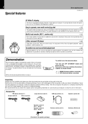
... fails to reproduce heavy bass more powerfully than conventional system speakers. 3-Disc carousel CD player ™ Three discs can be lost. Demonstration When the power supply is restored after a power failure or the power cord is also available on the remote control unit. To switch over the demonstration: Turn the unit OFF (STANDBY mode) and press the key. MODE /DEMO ÷ Press the key during use should you directly, notify the shipping company...
... fails to reproduce heavy bass more powerfully than conventional system speakers. 3-Disc carousel CD player ™ Three discs can be lost. Demonstration When the power supply is restored after a power failure or the power cord is also available on the remote control unit. To switch over the demonstration: Turn the unit OFF (STANDBY mode) and press the key. MODE /DEMO ÷ Press the key during use should you directly, notify the shipping company...
User Manual
Page 5
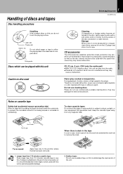
... hub to be played with this system because they may damage the internal mechanism. CD (12 cm, 8 cm), CDV (only the audio part) ÷ With CD-G (CD Graphics) discs, this unit to avoid malfunction, never use cleaning discs. Storage When a disc is very thin, the tape could damage the mechanism of discs and tapes Disc handling precautions 5 Before applying power XD-SERIES (En) Handling Hold compact discs so that these...
... hub to be played with this system because they may damage the internal mechanism. CD (12 cm, 8 cm), CDV (only the audio part) ÷ With CD-G (CD Graphics) discs, this unit to avoid malfunction, never use cleaning discs. Storage When a disc is very thin, the tape could damage the mechanism of discs and tapes Disc handling precautions 5 Before applying power XD-SERIES (En) Handling Hold compact discs so that these...
User Manual
Page 6
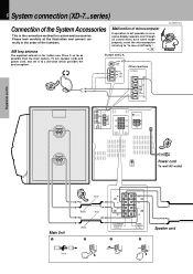
... antenna P The supplied antenna is the connection method for indoor use. R + SUB WOOFER SPEAKERS (12-16Ω) 3 + L - - FM 75Ω Other countries ANTENNA AM GND FM 75Ω 2 GND FM 300Ω AM XD-SERIES (En) Speaker (right) −+ L ANTENNA R AUX OUTPUT L R AUX INPUT AUX INPUT LEVEL FM 75Ω GND FM 300Ω AM MIN. MAX. + L - - Preparation section 6 System connection (XD-7...series) Connection of the System Accessories Malfunction of microcomputer This is for system...
... antenna P The supplied antenna is the connection method for indoor use. R + SUB WOOFER SPEAKERS (12-16Ω) 3 + L - - FM 75Ω Other countries ANTENNA AM GND FM 75Ω 2 GND FM 300Ω AM XD-SERIES (En) Speaker (right) −+ L ANTENNA R AUX OUTPUT L R AUX INPUT AUX INPUT LEVEL FM 75Ω GND FM 300Ω AM MIN. MAX. + L - - Preparation section 6 System connection (XD-7...series) Connection of the System Accessories Malfunction of microcomputer This is for system...
User Manual
Page 7
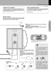
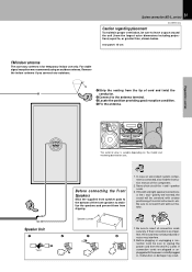
.... rear panel: 10 cm FM indoor antenna The accessory antenna is a magnet or other device generating magnetic force nearby, interaction between the magnet and speaker may cause color blotching onthe TV. speaker cords. 3. Be sure to insert all connection cords securely. Speaker and TV installation If there is for temporary indoor use only. If their connections are plugged or un- Before connecting the Front Speakers Stick the supplied...
.... rear panel: 10 cm FM indoor antenna The accessory antenna is a magnet or other device generating magnetic force nearby, interaction between the magnet and speaker may cause color blotching onthe TV. speaker cords. 3. Be sure to insert all connection cords securely. Speaker and TV installation If there is for temporary indoor use only. If their connections are plugged or un- Before connecting the Front Speakers Stick the supplied...
User Manual
Page 8
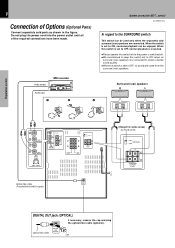
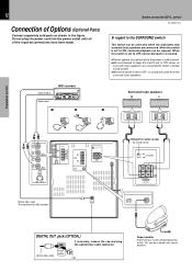
... DIGITAL OUT jack (OPTICAL) If necessary, remove the cap and plug the optical-fiber cable (optional). Preparation section 8 Connection of the required connections have been made. System connection (XD-7...series) XD-SERIES (En) In regard to OFF, no surround (rear) speakers are connected. When the switch is set to OFF when no sound will come from the surround (rear) speakers. When this switch is set to OFF, normal playback is executed. ÷ Please operate this switch while the power is switched...
... DIGITAL OUT jack (OPTICAL) If necessary, remove the cap and plug the optical-fiber cable (optional). Preparation section 8 Connection of the required connections have been made. System connection (XD-7...series) XD-SERIES (En) In regard to OFF, no surround (rear) speakers are connected. When the switch is set to OFF when no sound will come from the surround (rear) speakers. When this switch is set to OFF, normal playback is executed. ÷ Please operate this switch while the power is switched...
User Manual
Page 10
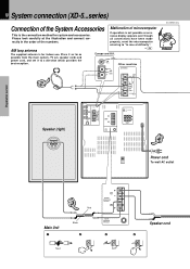
... System connection (XD-5...series) Connection of the System Accessories Malfunction of the numbers. If operation is for system and accessories. all connections have been made rectly in the order of microcomputer This is the connection method for indoor use. FM 75Ω Other countries ANTENNA AM GND FM 75Ω 2 GND FM 300Ω AM XD-SERIES (En) Preparation section Basic section Speaker (right) −+ L ANTENNA R AUX OUTPUT L R AUX INPUT AUX INPUT LEVEL...
... System connection (XD-5...series) Connection of the System Accessories Malfunction of the numbers. If operation is for system and accessories. all connections have been made rectly in the order of microcomputer This is the connection method for indoor use. FM 75Ω Other countries ANTENNA AM GND FM 75Ω 2 GND FM 300Ω AM XD-SERIES (En) Preparation section Basic section Speaker (right) −+ L ANTENNA R AUX OUTPUT L R AUX INPUT AUX INPUT LEVEL...
User Manual
Page 11
... 11 System connection (XD-5...series) XD-SERIES (En) Caution regarding placement To maintain proper ventilation, be sure to unplug the power cord from the wall AC outlet. speaker cords. 3. polarity are inverted, the sound will be produced or noise may result. For stable signal reception we recommend using an outdoor antenna. Speaker cushion 2 3 Notes 1. Preparation section Basic section Application section Speaker (left) BASS REFLEX SPEAKER SYSTEM BASS REFLEX SPEAKER SYSTEM −...
... 11 System connection (XD-5...series) XD-SERIES (En) Caution regarding placement To maintain proper ventilation, be sure to unplug the power cord from the wall AC outlet. speaker cords. 3. polarity are inverted, the sound will be produced or noise may result. For stable signal reception we recommend using an outdoor antenna. Speaker cushion 2 3 Notes 1. Preparation section Basic section Application section Speaker (left) BASS REFLEX SPEAKER SYSTEM BASS REFLEX SPEAKER SYSTEM −...
User Manual
Page 12
... Application section Knowledge sections DIGITAL OUT jack (OPTICAL) If necessary, remove the cap and plug the optical-fiber cable (optional). Preparation section Audio output MD recorder Audio input 1 2 Surround (rear) speakers R L 3 −+ −+ Basic section L R AUX OUTPUT L R AUX INPUT AUX INPUT LEVEL L ANTENNA R AUX OUTPUT L R AUX INPUT AUX INPUT LEVEL FM 75Ω GND FM 300Ω AM MIN. System connection (XD-5...series) XD-SERIES (En) In regard to the SURROUND switch This switch can be used only when the separately sold parts as shown in the...
... Application section Knowledge sections DIGITAL OUT jack (OPTICAL) If necessary, remove the cap and plug the optical-fiber cable (optional). Preparation section Audio output MD recorder Audio input 1 2 Surround (rear) speakers R L 3 −+ −+ Basic section L R AUX OUTPUT L R AUX INPUT AUX INPUT LEVEL L ANTENNA R AUX OUTPUT L R AUX INPUT AUX INPUT LEVEL FM 75Ω GND FM 300Ω AM MIN. System connection (XD-5...series) XD-SERIES (En) In regard to the SURROUND switch This switch can be used only when the separately sold parts as shown in the...
User Manual
Page 14
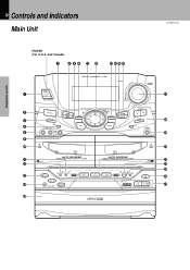
... SOUND SET 0 PUSH OPEN DOWN MULTI CONTROL SRS 3D CD PGM DUBBING ENTER TUNING BAND AUTO PHONES 0 PUSH OPEN PLAY REC /PLAY DISC 1 REV.MODE DOLBY NR 1 2 7 DISC 2 DISC SKIP DISC 3 REC/ARM 3 ¡ A/B 0 4¢ 76 & * ( Basic section Application section Knowledge sections MIC -2 INPUT MIC VOL. 14 Controls and indicators Main Unit XD-SERIES (En) Preparation section POWER (For U.S.A. BASS DISPLAY TIMER MODE /DEMO 1- and Canada) 7 890 ! @ # $%^ 1 2 3 4 5 6 ) ¡ ™ ¶ • ª MINI HiFi COMPONENT SYSTEM SRS ( ) UP VOLUME CONTROL...
... SOUND SET 0 PUSH OPEN DOWN MULTI CONTROL SRS 3D CD PGM DUBBING ENTER TUNING BAND AUTO PHONES 0 PUSH OPEN PLAY REC /PLAY DISC 1 REV.MODE DOLBY NR 1 2 7 DISC 2 DISC SKIP DISC 3 REC/ARM 3 ¡ A/B 0 4¢ 76 & * ( Basic section Application section Knowledge sections MIC -2 INPUT MIC VOL. 14 Controls and indicators Main Unit XD-SERIES (En) Preparation section POWER (For U.S.A. BASS DISPLAY TIMER MODE /DEMO 1- and Canada) 7 890 ! @ # $%^ 1 2 3 4 5 6 ) ¡ ™ ¶ • ª MINI HiFi COMPONENT SYSTEM SRS ( ) UP VOLUME CONTROL...
User Manual
Page 15
... stops it . %DUBBING key ‹ti Used for tape dubbing or CD recording onto tape. ^CD PGM key › Used for programming CD tracks. &VOLUME CONTROL knob ) This is also used for the equalizer mode setting, etc. 15 Controls and indicators XD-SERIES (En) ! This is used for setting or selection of the disc tray. ª Disc tray Three discs can be operated. BASS (Extra bass) key ¡ Switches the extra bass play on and off . Pressing the key...
... stops it . %DUBBING key ‹ti Used for tape dubbing or CD recording onto tape. ^CD PGM key › Used for programming CD tracks. &VOLUME CONTROL knob ) This is also used for the equalizer mode setting, etc. 15 Controls and indicators XD-SERIES (En) ! This is used for setting or selection of the disc tray. ª Disc tray Three discs can be operated. BASS (Extra bass) key ¡ Switches the extra bass play on and off . Pressing the key...
User Manual
Page 16
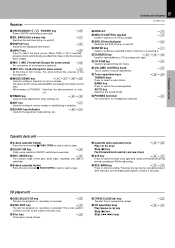
... information includes the tape reverse mode and tape transport direction. 7CD player indicators This section displays the CD playback and pause mode information as well as the disc number being played. 8Track number indicator Indicates the CD track number being played. 9Spectrum analyzer display 0RUNNING INDICATOR This indicator rotates according to the operation modes during volume control. ! They may differ from what actually appears on the display.) Controls and indicators XD-SERIES (En) Preparation...
... information includes the tape reverse mode and tape transport direction. 7CD player indicators This section displays the CD playback and pause mode information as well as the disc number being played. 8Track number indicator Indicates the CD track number being played. 9Spectrum analyzer display 0RUNNING INDICATOR This indicator rotates according to the operation modes during volume control. ! They may differ from what actually appears on the display.) Controls and indicators XD-SERIES (En) Preparation...

User Manual
Page 17
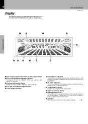
....BASS 7 8 9 EQ ON/OFF DISC SKIP 0 +10 INPUT TIME RANDOM REPEAT BAND TUNING TAPE CD A/B P.CALL MUTE MENU SET ENTER VOLUME MULTI CONTROL REMOTE CONTROL UNIT RC-701R ! @ Europe and U.K. : RC-701R Other countries : RC-701 Model: See left and right keys have the same function as the MULTI CONTROL jog dial on the amplifier/tuner unit. Infrared ray system. 17 Controls and indicators XD-SERIES (En) Preparation section 2Numeric keys Used...
....BASS 7 8 9 EQ ON/OFF DISC SKIP 0 +10 INPUT TIME RANDOM REPEAT BAND TUNING TAPE CD A/B P.CALL MUTE MENU SET ENTER VOLUME MULTI CONTROL REMOTE CONTROL UNIT RC-701R ! @ Europe and U.K. : RC-701R Other countries : RC-701 Model: See left and right keys have the same function as the MULTI CONTROL jog dial on the amplifier/tuner unit. Infrared ray system. 17 Controls and indicators XD-SERIES (En) Preparation section 2Numeric keys Used...
User Manual
Page 20
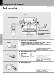
20 Let's put out some sound Basic use method XD-SERIES (En) Preparation section Basic section Bass and treble compensation TIMER, MODE/DEMO 1 3 EX.BASS 2 Muting the sound temporarily SET ENTER Listening through headphones Insert the headphone plug into deck B. 3. Volume adjustment DOWN 3 ÷ Quick turning produces a larger change amount. (AI VOLUME control function) ÷ The display shows a reference value. Application section Knowledge sections Selecting the desired output TUNER (Radio) CD TAPE AUX (External input) • ™ ¢...
20 Let's put out some sound Basic use method XD-SERIES (En) Preparation section Basic section Bass and treble compensation TIMER, MODE/DEMO 1 3 EX.BASS 2 Muting the sound temporarily SET ENTER Listening through headphones Insert the headphone plug into deck B. 3. Volume adjustment DOWN 3 ÷ Quick turning produces a larger change amount. (AI VOLUME control function) ÷ The display shows a reference value. Application section Knowledge sections Selecting the desired output TUNER (Radio) CD TAPE AUX (External input) • ™ ¢...

User Manual
Page 21
... volume. ÷ The sound muting is also canceled when the volume is selected. Preparation section MODE /DEMO 2 Select "S.W." and press the SET key. When CD has been selected. MULTI CONTROL SET SLEEP TIME SET O.T.T. MULTI CONTROL AUTOTPOW ER | Scrolled display (AUTO POWER SAVE) ON ..... sW sUB LEVE L 3 Select the desired level and press the ENTER key. RETURN ÷ This function is not available when the AUX input is controlled...
... volume. ÷ The sound muting is also canceled when the volume is selected. Preparation section MODE /DEMO 2 Select "S.W." and press the SET key. When CD has been selected. MULTI CONTROL SET SLEEP TIME SET O.T.T. MULTI CONTROL AUTOTPOW ER | Scrolled display (AUTO POWER SAVE) ON ..... sW sUB LEVE L 3 Select the desired level and press the ENTER key. RETURN ÷ This function is not available when the AUX input is controlled...

User Manual
Page 49
... section Basic section Balance adjustment : 1 Press the MODE/DEMO key. Select. 2. Press SET. AUX INPUT LEVEL The level is decreased. 2 Press the ENTER key. Adjusts the volume of left volume is decreased. Adjustment of the 3D effect) also is too high etc. MULTI CONTROL SET 3 Adjust. 1 Adjust. MULTI CONTROL The right volume is MIN. Indicates the center L--y--R Indicates the balance setting Input level adjustment : Rear panel L ANTENNA FM R AUX 75Ω OUTPUT L R AUX INPUT AUX INPUT LEVEL AM GND...
... section Basic section Balance adjustment : 1 Press the MODE/DEMO key. Select. 2. Press SET. AUX INPUT LEVEL The level is decreased. 2 Press the ENTER key. Adjusts the volume of left volume is decreased. Adjustment of the 3D effect) also is too high etc. MULTI CONTROL SET 3 Adjust. 1 Adjust. MULTI CONTROL The right volume is MIN. Indicates the center L--y--R Indicates the balance setting Input level adjustment : Rear panel L ANTENNA FM R AUX 75Ω OUTPUT L R AUX INPUT AUX INPUT LEVEL AM GND...

User Manual
Page 56
... play (recording). ÷ To listen to radio ÷ To listen to CD ÷ To listen to the AUX jacks. ÷ For recording Make prepara- MULTI CONTROL SET SLEEP TIME SET O.T.T. Program 2 AUTO POWER SAVE PROG 1 ÷ The selected program No. lights. ÷ If a program No. The time is advanced. SET The time is returned. AM7 O0 PROG.1 Knowledge sections PROG. A ÷ Playing the auxiliary input source Make timer setting of the component connected to tape The station should be restarted.) 1 Make...
... play (recording). ÷ To listen to radio ÷ To listen to CD ÷ To listen to the AUX jacks. ÷ For recording Make prepara- MULTI CONTROL SET SLEEP TIME SET O.T.T. Program 2 AUTO POWER SAVE PROG 1 ÷ The selected program No. lights. ÷ If a program No. The time is advanced. SET The time is returned. AM7 O0 PROG.1 Knowledge sections PROG. A ÷ Playing the auxiliary input source Make timer setting of the component connected to tape The station should be restarted.) 1 Make...

User Manual
Page 57
... CONTROL 57 Adjust the clock before setting the timer. The time is The time is returned. Select "TIMER PLAY" or "AI PLAY". MULTI CONTROL SET Continued on next page... PROG ON /O PROG. Program 1 PROG.2 ...... advanced. SLEEP | Scrolled display (PROG. TIMER PL AY For timer recording 1 Select the mode. Select the source to be played. ON/OFF PROG.1 ...... Program 2 AUTO POWER SAVE ENTER Enter it . Timer operation XD-SERIES (En) ÷ After entering the figure of "minute" using...
... CONTROL 57 Adjust the clock before setting the timer. The time is The time is returned. Select "TIMER PLAY" or "AI PLAY". MULTI CONTROL SET Continued on next page... PROG ON /O PROG. Program 1 PROG.2 ...... advanced. SLEEP | Scrolled display (PROG. TIMER PL AY For timer recording 1 Select the mode. Select the source to be played. ON/OFF PROG.1 ...... Program 2 AUTO POWER SAVE ENTER Enter it . Timer operation XD-SERIES (En) ÷ After entering the figure of "minute" using...
User Manual
Page 59
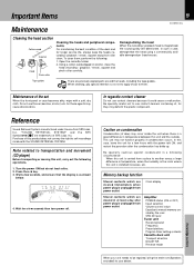
... immediately when power plug is unplugged from power outlet Amplifier POWER status (ON or OFF) Input selection Volume control value Equalizer's manual memory created by the user SRS 3D level Tuner unit Receiving band Frequency Preset stations Program timer setting contents Cassette deck unit Transport direction DOLBY NR Reverse mode Knowledge sections When your unit needs to use thinner, benzine, alcohol, etc. Preparation section Basic section Application section Reference Sound Retrieval System manufactured...
... immediately when power plug is unplugged from power outlet Amplifier POWER status (ON or OFF) Input selection Volume control value Equalizer's manual memory created by the user SRS 3D level Tuner unit Receiving band Frequency Preset stations Program timer setting contents Cassette deck unit Transport direction DOLBY NR Reverse mode Knowledge sections When your unit needs to use thinner, benzine, alcohol, etc. Preparation section Basic section Application section Reference Sound Retrieval System manufactured...

User Manual
Page 60
... no tape or CD set is installed near the system. ÷ Install the outdoor antenna in the TUNER mode. ÷ Sound is not output when the radio wave is not pro- ÷ The AUX INPUT LEVEL control on the rear ÷ Adjust to an optimum level. Cause ÷ Batteries are disconnected. ÷ The MUTE switch of remote control unit is switched ON. ÷ The headphone plug is inserted into malfunction (impossibility to operate, erroneous display...
... no tape or CD set is installed near the system. ÷ Install the outdoor antenna in the TUNER mode. ÷ Sound is not output when the radio wave is not pro- ÷ The AUX INPUT LEVEL control on the rear ÷ Adjust to an optimum level. Cause ÷ Batteries are disconnected. ÷ The MUTE switch of remote control unit is switched ON. ÷ The headphone plug is inserted into malfunction (impossibility to operate, erroneous display...


