
User Manual
Page 3
... discs and tapes 5 System connection (XD-7...series 6 Connection of the System Accessories 6 Connection of Options (Optional Parts 8 System connection (XD-5...series 10 Connection of the System Accessories 10 Connection of Options (Optional Parts 12 Controls and indicators 14 Main Unit 14 Display 16 Remote control Unit 17 Operation of remote control unit 18 CHANNEL SPACE setting 18 Basic section Let's put out some sound 20 Basic use method 20 Playback of CD 22 Playback of tape 24 Searching for the desired music program...
... discs and tapes 5 System connection (XD-7...series 6 Connection of the System Accessories 6 Connection of Options (Optional Parts 8 System connection (XD-5...series 10 Connection of the System Accessories 10 Connection of Options (Optional Parts 12 Controls and indicators 14 Main Unit 14 Display 16 Remote control Unit 17 Operation of remote control unit 18 CHANNEL SPACE setting 18 Basic section Let's put out some sound 20 Basic use method 20 Playback of CD 22 Playback of tape 24 Searching for the desired music program...
User Manual
Page 4
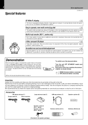
... heavy bass more powerfully than conventional system speakers. 3-Disc carousel CD player ™ Three discs can file a claim against the carrier for use , this unit automatically starts the demonstration function (display only). To switch over the demonstration: Turn the unit OFF (STANDBY mode) and press the key. Versatile tone and sound field adjustment p Equalizer patterns can not only be selected from preset patterns, but the audio does not change. If...
... heavy bass more powerfully than conventional system speakers. 3-Disc carousel CD player ™ Three discs can file a claim against the carrier for use , this unit automatically starts the demonstration function (display only). To switch over the demonstration: Turn the unit OFF (STANDBY mode) and press the key. Versatile tone and sound field adjustment p Equalizer patterns can not only be selected from preset patterns, but the audio does not change. If...
User Manual
Page 5
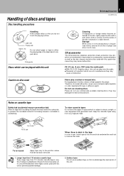
... audio part) ÷ With CD-G (CD Graphics) discs, this unit can be played with this unit Caution on accidentally. Basic section Application section Knowledge sections To re-record Apply tape only to either the playing side or the label side of compact discs. Therefore, to avoid malfunction, never use cleaning discs. Keep the cassette tapes away from the center of the disc outwards in the player...
... audio part) ÷ With CD-G (CD Graphics) discs, this unit can be played with this unit Caution on accidentally. Basic section Application section Knowledge sections To re-record Apply tape only to either the playing side or the label side of compact discs. Therefore, to avoid malfunction, never use cleaning discs. Keep the cassette tapes away from the center of the disc outwards in the player...
User Manual
Page 6
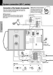
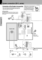
...) Speaker (right) −+ L ANTENNA R AUX OUTPUT L R AUX INPUT AUX INPUT LEVEL FM 75Ω GND FM 300Ω AM MIN. R + SUB WOOFER SPEAKERS (12-16Ω) 3 + L - - R + FRONT SPEAKERS (6-16Ω) 4 Speaker cord R + SUB WOOFER SPEAKERS (12-16Ω) + L - - If operation is for system and accessories. possible from the main system, TV set, speaker cords and power cord, and set it as far as Europe and U.K. R + FRONT SPEAKERS (6-16Ω) % ON SURROUND fi OFF -+ L R SURROUND SPEAKERS (6-16Ω) 4 −+ Power cord DIGITAL...
...) Speaker (right) −+ L ANTENNA R AUX OUTPUT L R AUX INPUT AUX INPUT LEVEL FM 75Ω GND FM 300Ω AM MIN. R + SUB WOOFER SPEAKERS (12-16Ω) 3 + L - - R + FRONT SPEAKERS (6-16Ω) 4 Speaker cord R + SUB WOOFER SPEAKERS (12-16Ω) + L - - If operation is for system and accessories. possible from the main system, TV set, speaker cords and power cord, and set it as far as Europe and U.K. R + FRONT SPEAKERS (6-16Ω) % ON SURROUND fi OFF -+ L R SURROUND SPEAKERS (6-16Ω) 4 −+ Power cord DIGITAL...
User Manual
Page 7
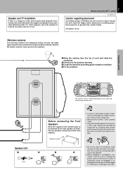
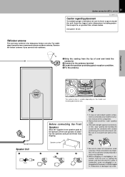
... use only. Before connecting the Front Speakers Stick the supplied front speaker pads to stabilize the speakers and prevent them without mistake. In case an associated system component is connected, also read the instruction manual of the front speakers to the bottom of the component. 2. Be sure to leave a space around the unit (from the tip of musical instruments, etc. rear panel: 10 cm FM indoor antenna...
... use only. Before connecting the Front Speakers Stick the supplied front speaker pads to stabilize the speakers and prevent them without mistake. In case an associated system component is connected, also read the instruction manual of the front speakers to the bottom of the component. 2. Be sure to leave a space around the unit (from the tip of musical instruments, etc. rear panel: 10 cm FM indoor antenna...
User Manual
Page 8
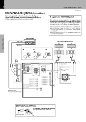
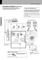
... cord into the power outlet until all of Options (Optional Parts) Connect separately sold surround (rear) speakers are connected to obtain a better sound quality. ÷ When the switch is set to OFF, no surround (rear) speakers are connected. System connection (XD-7...series) XD-SERIES (En) In regard to the SURROUND switch This switch can be used only when the separately sold parts as shown in the figure. MAX. + L - - R + SUB WOOFER SPEAKERS (12-16Ω) + L - - Audio output MD recorder Audio input 1 2 Surround (rear) speakers R L 3 −+ −+ L R AUX...
... cord into the power outlet until all of Options (Optional Parts) Connect separately sold surround (rear) speakers are connected to obtain a better sound quality. ÷ When the switch is set to OFF, no surround (rear) speakers are connected. System connection (XD-7...series) XD-SERIES (En) In regard to the SURROUND switch This switch can be used only when the separately sold parts as shown in the figure. MAX. + L - - R + SUB WOOFER SPEAKERS (12-16Ω) + L - - Audio output MD recorder Audio input 1 2 Surround (rear) speakers R L 3 −+ −+ L R AUX...
User Manual
Page 10
... section Speaker (right) −+ L ANTENNA R AUX OUTPUT L R AUX INPUT AUX INPUT LEVEL FM 75Ω GND FM 300Ω AM MIN. If operation is for system and accessories. Place it to "In case of difficulty". possible from the main system, TV set, speaker cords and power cord, and set it as far as Europe and U.K. MAX. + L - FRONT SPEAKERS (6-16Ω) - R + SUPER WOOFER PRE OUT 3 Twist Speaker cord 4 10 System connection (XD-5...series) Connection of the System...
... section Speaker (right) −+ L ANTENNA R AUX OUTPUT L R AUX INPUT AUX INPUT LEVEL FM 75Ω GND FM 300Ω AM MIN. If operation is for system and accessories. Place it to "In case of difficulty". possible from the main system, TV set, speaker cords and power cord, and set it as far as Europe and U.K. MAX. + L - FRONT SPEAKERS (6-16Ω) - R + SUPER WOOFER PRE OUT 3 Twist Speaker cord 4 10 System connection (XD-5...series) Connection of the System...
User Manual
Page 11
... Before connecting the Front Speakers Stick the supplied front speaker pads to the bottom of cord and twist the conductor. 1 2 Connect to , or greater than, shown below. For stable signal reception we recommend using an outdoor antenna. In case an associated system component is connected, also read the instruction manual of musical instruments, etc. polarity are inverted, the sound will be unnatural with the power cord left plugged...
... Before connecting the Front Speakers Stick the supplied front speaker pads to the bottom of cord and twist the conductor. 1 2 Connect to , or greater than, shown below. For stable signal reception we recommend using an outdoor antenna. In case an associated system component is connected, also read the instruction manual of musical instruments, etc. polarity are inverted, the sound will be unnatural with the power cord left plugged...
User Manual
Page 12
Do not plug the power cord into the power outlet until all of the required connections have been made. System connection (XD-5...series) XD-SERIES (En) In regard to the SURROUND switch This switch can be used only when the separately sold parts as shown in the figure. Optical-fiber cable DIGITAL OUT OPTICAL Cap Super woofer Extremely low sound is set to OFF, no surround (rear) speakers are connected. When this switch is set to OFF, normal playback...
Do not plug the power cord into the power outlet until all of the required connections have been made. System connection (XD-5...series) XD-SERIES (En) In regard to the SURROUND switch This switch can be used only when the separately sold parts as shown in the figure. Optical-fiber cable DIGITAL OUT OPTICAL Cap Super woofer Extremely low sound is set to OFF, no surround (rear) speakers are connected. When this switch is set to OFF, normal playback...
User Manual
Page 14
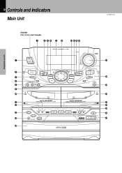
...# $%^ 1 2 3 4 5 6 ) ¡ ™ ¶ • ª MINI HiFi COMPONENT SYSTEM SRS ( ) UP VOLUME CONTROL ON/STANDBY EX. MIC -2 INPUT MIC VOL. BASS DISPLAY TIMER MODE /DEMO 1- MIN MAX SOUND SET 0 PUSH OPEN DOWN MULTI CONTROL SRS 3D CD PGM DUBBING ENTER TUNING BAND AUTO PHONES 0 PUSH OPEN PLAY REC /PLAY DISC 1 REV.MODE DOLBY NR 1 2 7 DISC 2 DISC SKIP DISC 3 REC/ARM 3 ¡ A/B 0 4¢ 76 & * ( Basic section Application section Knowledge sections 14 Controls and indicators Main Unit XD-SERIES (En) Preparation section POWER (For U.S.A.
...# $%^ 1 2 3 4 5 6 ) ¡ ™ ¶ • ª MINI HiFi COMPONENT SYSTEM SRS ( ) UP VOLUME CONTROL ON/STANDBY EX. MIC -2 INPUT MIC VOL. BASS DISPLAY TIMER MODE /DEMO 1- MIN MAX SOUND SET 0 PUSH OPEN DOWN MULTI CONTROL SRS 3D CD PGM DUBBING ENTER TUNING BAND AUTO PHONES 0 PUSH OPEN PLAY REC /PLAY DISC 1 REV.MODE DOLBY NR 1 2 7 DISC 2 DISC SKIP DISC 3 REC/ARM 3 ¡ A/B 0 4¢ 76 & * ( Basic section Application section Knowledge sections 14 Controls and indicators Main Unit XD-SERIES (En) Preparation section POWER (For U.S.A.
User Manual
Page 15
... mode setting, etc. 15 Controls and indicators XD-SERIES (En) ! When power is opened and closed. ⁄ CD operation keys Play/pause (6) key Stop (7) key Skip (4 ¢) keys ™ ™£ Knowledge sections DISPLAY ^ @MULTI CONTROL jog dial ( Used for selection of various modes. #SRS 3D key/Indicator Switches the SRS 3D play on and off . 8 TIMER key RI Used for time adjustment, timer setting, etc. 9 SET key ¡ Used for volume adjustment. *Tuner operation keys •ª TUNING...
... mode setting, etc. 15 Controls and indicators XD-SERIES (En) ! When power is opened and closed. ⁄ CD operation keys Play/pause (6) key Stop (7) key Skip (4 ¢) keys ™ ™£ Knowledge sections DISPLAY ^ @MULTI CONTROL jog dial ( Used for selection of various modes. #SRS 3D key/Indicator Switches the SRS 3D play on and off . 8 TIMER key RI Used for time adjustment, timer setting, etc. 9 SET key ¡ Used for volume adjustment. *Tuner operation keys •ª TUNING...
User Manual
Page 16
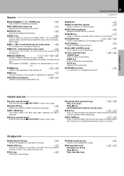
... tape reverse mode and tape transport direction. 7CD player indicators This section displays the CD playback and pause mode information as well as the disc number being played. 8Track number indicator Indicates the CD track number being played. 9Spectrum analyzer display 0RUNNING INDICATOR This indicator rotates according to the operation modes during operation of the tuner operations and applied CD operations. 3 Character information display Displays the input selection, frequency, volume level, etc. 4 Tone and sound field-related indicators 5 Timer...
... tape reverse mode and tape transport direction. 7CD player indicators This section displays the CD playback and pause mode information as well as the disc number being played. 8Track number indicator Indicates the CD track number being played. 9Spectrum analyzer display 0RUNNING INDICATOR This indicator rotates according to the operation modes during operation of the tuner operations and applied CD operations. 3 Character information display Displays the input selection, frequency, volume level, etc. 4 Tone and sound field-related indicators 5 Timer...

User Manual
Page 17
... a certain content. RDS DISP. PTY POWER 1 2 3 SRS 3D 4 5 6 EX.BASS 7 8 9 EQ ON/OFF DISC SKIP 0 +10 INPUT TIME RANDOM REPEAT BAND TUNING TAPE CD A/B P.CALL MUTE MENU SET ENTER VOLUME MULTI CONTROL REMOTE CONTROL UNIT RC-701R ! @ Europe and U.K. : RC-701R Other countries : RC-701 Model: See left and right keys have the same function as number keys when the input is CD or TUNER. £ 3DISC SKIP key...
... a certain content. RDS DISP. PTY POWER 1 2 3 SRS 3D 4 5 6 EX.BASS 7 8 9 EQ ON/OFF DISC SKIP 0 +10 INPUT TIME RANDOM REPEAT BAND TUNING TAPE CD A/B P.CALL MUTE MENU SET ENTER VOLUME MULTI CONTROL REMOTE CONTROL UNIT RC-701R ! @ Europe and U.K. : RC-701R Other countries : RC-701 Model: See left and right keys have the same function as number keys when the input is CD or TUNER. £ 3DISC SKIP key...
User Manual
Page 20
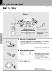
... the component connected to the AUX input jacks. (AUX INPUT LEVEL adjustment o) ÷ When CD or TAPE is switched OFF. (DIMMER function) 2. Volume adjustment DOWN 3 ÷ Quick turning produces a larger change amount. (AI VOLUME control function) ÷ The display shows a reference value. 20 Let's put out some sound Basic use method XD-SERIES (En) Preparation section Basic section Bass and treble compensation TIMER, MODE/DEMO 1 3 EX.BASS 2 Muting the sound temporarily SET ENTER Listening through headphones Insert the headphone plug into...
... the component connected to the AUX input jacks. (AUX INPUT LEVEL adjustment o) ÷ When CD or TAPE is switched OFF. (DIMMER function) 2. Volume adjustment DOWN 3 ÷ Quick turning produces a larger change amount. (AI VOLUME control function) ÷ The display shows a reference value. 20 Let's put out some sound Basic use method XD-SERIES (En) Preparation section Basic section Bass and treble compensation TIMER, MODE/DEMO 1 3 EX.BASS 2 Muting the sound temporarily SET ENTER Listening through headphones Insert the headphone plug into...

User Manual
Page 21
... the MODE/DEMO key. CD 01 0 00 123 Volume display VOL 5 7 123 AUTO POWER SAVE function When the power is ON and neither recording nor playback is executed for the XD-5...series) XD-SERIES (En) Adjust the sub woofer level according to the category of current is controlled. Auto power save is used . Auto power save is not ENTER used . RETURN ÷ This function is not available when the AUX input is ON...
... the MODE/DEMO key. CD 01 0 00 123 Volume display VOL 5 7 123 AUTO POWER SAVE function When the power is ON and neither recording nor playback is executed for the XD-5...series) XD-SERIES (En) Adjust the sub woofer level according to the category of current is controlled. Auto power save is used . Auto power save is not ENTER used . RETURN ÷ This function is not available when the AUX input is ON...

User Manual
Page 49
... equalizer as required when the volume from external equipment is decreased. Select the sound field mode according to the music genre. Input level.......Adjusts the volume of the 3D effect) also is decreased. Preparation section Basic section Balance adjustment : 1 Press the MODE/DEMO key. Select. 2. MULTI CONTROL SET 3 Adjust. 1 Adjust. Indicates the center L--y--R Indicates the balance setting Input level adjustment : Rear panel L ANTENNA FM R AUX 75Ω OUTPUT L R AUX INPUT AUX INPUT LEVEL AM GND FM 300...
... equalizer as required when the volume from external equipment is decreased. Select the sound field mode according to the music genre. Input level.......Adjusts the volume of the 3D effect) also is decreased. Preparation section Basic section Balance adjustment : 1 Press the MODE/DEMO key. Select. 2. MULTI CONTROL SET 3 Adjust. 1 Adjust. Indicates the center L--y--R Indicates the balance setting Input level adjustment : Rear panel L ANTENNA FM R AUX 75Ω OUTPUT L R AUX INPUT AUX INPUT LEVEL AM GND FM 300...

User Manual
Page 56
... to radio ÷ To listen to CD ÷ To listen to tape The station should be activated or not as required. ÷ Timer reservation is not possible.) Set a tape into deck B. TIMER 4 Select a program No. MULTI CONTROL SET SLEEP TIME SET O.T.T. The time is advanced. A ÷ Playing the auxiliary input source Make timer setting of timer playback. 2 Adjust the listening volume. UP VOLUME CONTROL DOWN 3 Press the TIMER key. ÷ When the timer function is used every day) and a sleep timer system...
... to radio ÷ To listen to CD ÷ To listen to tape The station should be activated or not as required. ÷ Timer reservation is not possible.) Set a tape into deck B. TIMER 4 Select a program No. MULTI CONTROL SET SLEEP TIME SET O.T.T. The time is advanced. A ÷ Playing the auxiliary input source Make timer setting of timer playback. 2 Adjust the listening volume. UP VOLUME CONTROL DOWN 3 Press the TIMER key. ÷ When the timer function is used every day) and a sleep timer system...

User Manual
Page 57
advanced. creasing volume SET RETURN Enter it . TIMER PLAY TIMER REC AI PLAY RETURN SET Enter it . SLEEP | Scrolled display (PROG. ON/OFF) TIME SET O.T.T. PROG ON /O PROG. Program 1 PROG.2 ...... For timer playback or AI timer playback 1 Select the mode. MULTI CONTROL ENTER TUNER (Radio) CD TAPE AUX (External input) RETURN TUNER Enter it . ÷ If you selected TUNER, press the SET key. 3 Select the broadcast station (only when TUNER is selected above ). TUNER (Radio) AUX (External input) RETURN ENTER Enter...
advanced. creasing volume SET RETURN Enter it . TIMER PLAY TIMER REC AI PLAY RETURN SET Enter it . SLEEP | Scrolled display (PROG. ON/OFF) TIME SET O.T.T. PROG ON /O PROG. Program 1 PROG.2 ...... For timer playback or AI timer playback 1 Select the mode. MULTI CONTROL ENTER TUNER (Radio) CD TAPE AUX (External input) RETURN TUNER Enter it . ÷ If you selected TUNER, press the SET key. 3 Select the broadcast station (only when TUNER is selected above ). TUNER (Radio) AUX (External input) RETURN ENTER Enter...
User Manual
Page 59
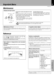
... a disc. 2. Memory backup function Stored contents which are cleared immediately when power plug is carried from power outlet Amplifier POWER status (ON or OFF) Input selection Volume control value Equalizer's manual memory created by the user SRS 3D level Tuner unit Receiving band Frequency Preset stations Program timer setting contents Cassette deck unit Transport direction DOLBY NR Reverse mode Knowledge sections When your dealer. In such a case, demagnetize the head using a commercially...
... a disc. 2. Memory backup function Stored contents which are cleared immediately when power plug is carried from power outlet Amplifier POWER status (ON or OFF) Input selection Volume control value Equalizer's manual memory created by the user SRS 3D level Tuner unit Receiving band Frequency Preset stations Program timer setting contents Cassette deck unit Transport direction DOLBY NR Reverse mode Knowledge sections When your dealer. In such a case, demagnetize the head using a commercially...

User Manual
Page 60
... power cord from the system, the controlling angle is deviated or there is an obstacle in the TUNER mode. ÷ Sound is not output when the radio wave is set to OFF. ÷ Adjust to an optimum level. Cause ÷ Batteries are disconnected. panel is ÷ Switch the demonstration off. Application section Knowledge sections R R Timer operation is made to "Clock R adjustment". ÷ Set the timer ON time and OFF time. right speakers. ÷ Connect...
... power cord from the system, the controlling angle is deviated or there is an obstacle in the TUNER mode. ÷ Sound is not output when the radio wave is set to OFF. ÷ Adjust to an optimum level. Cause ÷ Batteries are disconnected. panel is ÷ Switch the demonstration off. Application section Knowledge sections R R Timer operation is made to "Clock R adjustment". ÷ Set the timer ON time and OFF time. right speakers. ÷ Connect...


