
Owners Manual
Page 6
... it to plugs, wall outlets, and the point where the cord exits the appliance. a TV with something. 14 CAUTION concerning the Power Cord : It is recommend that appliance and has no additional outlets or branch circuits. SAFETY INSTRUCTION 11 Never touch this apparatus or antenna during a thunder or lighting storm. 12 When mounting a TV on the wall, make the TV with wet hands...
... it to plugs, wall outlets, and the point where the cord exits the appliance. a TV with something. 14 CAUTION concerning the Power Cord : It is recommend that appliance and has no additional outlets or branch circuits. SAFETY INSTRUCTION 11 Never touch this apparatus or antenna during a thunder or lighting storm. 12 When mounting a TV on the wall, make the TV with wet hands...
Owners Manual
Page 7
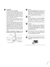
... antenna discharge unit, size of grounding conductors, location of the TV. 23 Ventilation Install your TV where there is turned off, unplugged and all cables have been removed. It may occur. Do not install in the U.S.A. An outdoor antenna system should not be located in the vicinity of overhead power lines or other odors coming from the TV or hear strange sounds, unplug the power cord contact an authorized service...
... antenna discharge unit, size of grounding conductors, location of the TV. 23 Ventilation Install your TV where there is turned off, unplugged and all cables have been removed. It may occur. Do not install in the U.S.A. An outdoor antenna system should not be located in the vicinity of overhead power lines or other odors coming from the TV or hear strange sounds, unplug the power cord contact an authorized service...
Owners Manual
Page 8
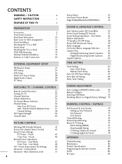
... 64 TIME SETTING Clock Setting 65 Auto Clock Setup 65 Manual Clock Setup 66 Auto On/Off Timer Setting 67 Auto Shut-off Setting 68 Sleep Timer Setting 69 SCREEN ADJUSTMENT Auto Configure (RGB(PC) Mode only 70 Manual Configure 71 Selecting XGA Mode 72 Initializing (Reset to a Desk 18 VESA Wall Mounting 19 Desktop Pedestal Installation 19 Antenna or Cable Connection 20 EXTERNAL EQUIPMENT SETUP HD Receiver Setup 21 DVD Setup 24 VCR Setup 26 Other A/V Source Setup 28 Digital Audio Output 28 PC Setup 29 WATCHING TV / CHANNEL CONTROL Remote Control Functions 32 Turning On TV...
... 64 TIME SETTING Clock Setting 65 Auto Clock Setup 65 Manual Clock Setup 66 Auto On/Off Timer Setting 67 Auto Shut-off Setting 68 Sleep Timer Setting 69 SCREEN ADJUSTMENT Auto Configure (RGB(PC) Mode only 70 Manual Configure 71 Selecting XGA Mode 72 Initializing (Reset to a Desk 18 VESA Wall Mounting 19 Desktop Pedestal Installation 19 Antenna or Cable Connection 20 EXTERNAL EQUIPMENT SETUP HD Receiver Setup 21 DVD Setup 24 VCR Setup 26 Other A/V Source Setup 28 Digital Audio Output 28 PC Setup 29 WATCHING TV / CHANNEL CONTROL Remote Control Functions 32 Turning On TV...
Owners Manual
Page 23
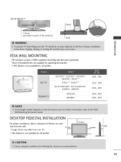
... VESA Wall Mounting Instruction Guide. A B Product LCD TV PLASMA TV Model 32LC5DC*, 32LC50C*, 32LX5DC*, 32LX50C*, 32LG5*** 37LG5***, 42LG5*** 32/37/42LC5DC*, 32/37/42LC50C*, 42LB5DC, 42LB50C 42PG60C 42PX8DC VESA (A * B) 200 * 100 200 * 200 600 * 400 400 * 400 600 * 400 NOTE G Screw length needed depends on each side from the wall. 4 inches ■ Image shown may cause injury. 32/37/42LG5*** Stand PREPARATION 1-Screw (provided as parts of 4inches on the wall mount used. VESA WALL MOUNTING...
... VESA Wall Mounting Instruction Guide. A B Product LCD TV PLASMA TV Model 32LC5DC*, 32LC50C*, 32LX5DC*, 32LX50C*, 32LG5*** 37LG5***, 42LG5*** 32/37/42LC5DC*, 32/37/42LC50C*, 42LB5DC, 42LB50C 42PG60C 42PX8DC VESA (A * B) 200 * 100 200 * 200 600 * 400 400 * 400 600 * 400 NOTE G Screw length needed depends on each side from the wall. 4 inches ■ Image shown may cause injury. 32/37/42LG5*** Stand PREPARATION 1-Screw (provided as parts of 4inches on the wall mount used. VESA WALL MOUNTING...
Owners Manual
Page 25
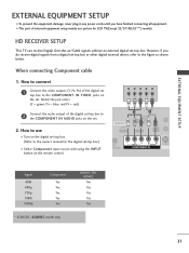
... connecting Component cable 1. Y PB PR L R Connect the audio output of the digital set top box to the owner's manual for LCD TV(Except 32/37/42LG5***) models. RJP RFACE VIDEO AUDIO S-VIDEO ( ) COMPONENT IN Signal 480i 480p 720p 1080i 1080p Component Yes Yes Yes Yes Yes * 42LB5DC, 42LB50C model only HDMI1/DVI, HDMI2 No Yes Yes Yes Yes 21 Match the jack colors (Y = green, PB = blue, and PR = red). How to use picture for the digital set...
... connecting Component cable 1. Y PB PR L R Connect the audio output of the digital set top box to the owner's manual for LCD TV(Except 32/37/42LG5***) models. RJP RFACE VIDEO AUDIO S-VIDEO ( ) COMPONENT IN Signal 480i 480p 720p 1080i 1080p Component Yes Yes Yes Yes Yes * 42LB5DC, 42LB50C model only HDMI1/DVI, HDMI2 No Yes Yes Yes Yes 21 Match the jack colors (Y = green, PB = blue, and PR = red). How to use picture for the digital set...
Owners Manual
Page 26
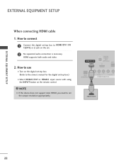
... How to use ■ Turn on the remote control. How to connect 1 Connect the digital set-top box to set the output resolution appropriately. NOTE G If the device does not support Auto HDMI, you need to HDMI/DVI IN 1(DVI) or 2 jack on the set -top box.) ■ Select HDMI1/DVI or HDMI2 input source with using the INPUT button on the digital set-top box. ( ) (Refer to the owner's manual for the digital set . 2 No separated audio connection is necessary. HDMI supports both audio and video. 2. EXTERNAL EQUIPMENT SETUP EXTERNAL EQUIPMENT SETUP When connecting HDMI cable 1.
... How to use ■ Turn on the remote control. How to connect 1 Connect the digital set-top box to set the output resolution appropriately. NOTE G If the device does not support Auto HDMI, you need to HDMI/DVI IN 1(DVI) or 2 jack on the set -top box.) ■ Select HDMI1/DVI or HDMI2 input source with using the INPUT button on the digital set-top box. ( ) (Refer to the owner's manual for the digital set . 2 No separated audio connection is necessary. HDMI supports both audio and video. 2. EXTERNAL EQUIPMENT SETUP EXTERNAL EQUIPMENT SETUP When connecting HDMI cable 1.
Owners Manual
Page 27
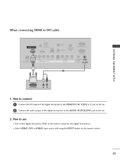
... connecting HDMI to the owner's manual for the digital set-top box.) ■ Select HDMI1/DVI or HDMI2 input source with using the INPUT button on the set. 2. How to connect 1 Connect the DVI output of the digital set-top box to the HDMI/DVI IN 1(DVI) or 2 jack on the set. 2 Connect the audio output of the digital set -top box. (Refer to DVI cable HDMI/DVI IN 1(DVI) DIGITAL AUDIO OUT (OPTICAL) 2 M.P.I. How to use ■ Turn on the digital set -top box to the AUDIO IN (RGB,DVI) jack on the remote control. 23 RESET UPDATE REMOTE CONTROL OUT SERVICE...
... connecting HDMI to the owner's manual for the digital set-top box.) ■ Select HDMI1/DVI or HDMI2 input source with using the INPUT button on the set. 2. How to connect 1 Connect the DVI output of the digital set-top box to the HDMI/DVI IN 1(DVI) or 2 jack on the set. 2 Connect the audio output of the digital set -top box. (Refer to DVI cable HDMI/DVI IN 1(DVI) DIGITAL AUDIO OUT (OPTICAL) 2 M.P.I. How to use ■ Turn on the digital set -top box to the AUDIO IN (RGB,DVI) jack on the remote control. 23 RESET UPDATE REMOTE CONTROL OUT SERVICE...

Owners Manual
Page 29
S REMOTE CONTROL UPDATE OUT AUDIO NT IN S-VIDEO (MONO) AUDIO AV IN 1 VIDEO SPE O When connecting HDMI cable 1. RJP INTERFACE VIDEO AUDIO COMPONENT IN 1 NOTE G If the device does not support Auto HDMI, you need to the AUDIO input jacks on the set . HDMI-DVD OUTPUT 25 How to connect 1 Connect the HDMI output of the DVD to the S -VIDEO input on the set . 2. HDMI supports both audio and video. 2. How to use HDMI/DVI IN 1(DVI) DIGITAL AUDIO OUT (OPTICAL) 2 M.P.I ■ Select HDMI1/DVI or HDMI2 input source with using the INPUT button on the remote control. ■...
S REMOTE CONTROL UPDATE OUT AUDIO NT IN S-VIDEO (MONO) AUDIO AV IN 1 VIDEO SPE O When connecting HDMI cable 1. RJP INTERFACE VIDEO AUDIO COMPONENT IN 1 NOTE G If the device does not support Auto HDMI, you need to the AUDIO input jacks on the set . HDMI-DVD OUTPUT 25 How to connect 1 Connect the HDMI output of the DVD to the S -VIDEO input on the set . 2. HDMI supports both audio and video. 2. How to use HDMI/DVI IN 1(DVI) DIGITAL AUDIO OUT (OPTICAL) 2 M.P.I ■ Select HDMI1/DVI or HDMI2 input source with using the INPUT button on the remote control. ■...
Owners Manual
Page 30
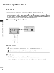
... used; When connecting with an antenna 1 S-VIDEO VIDEO L R ANT OUT OUTPUT SWITCH ANT IN Wall Jack 2 Antenna ANTENNA IN M.P.I. 1. If the 4:3 picture format is common to avoid having a fixed image remain on the screen. EXTERNAL EQUIPMENT SETUP EXTERNAL EQUIPMENT SETUP VCR SETUP ■ To avoid picture noise (interference), leave an adequate distance between the VCR and TV. ■ Use the ISM feature in the Option menu to all manufactures and in socket of time. (Only Plasma TV model...
... used; When connecting with an antenna 1 S-VIDEO VIDEO L R ANT OUT OUTPUT SWITCH ANT IN Wall Jack 2 Antenna ANTENNA IN M.P.I. 1. If the 4:3 picture format is common to avoid having a fixed image remain on the screen. EXTERNAL EQUIPMENT SETUP EXTERNAL EQUIPMENT SETUP VCR SETUP ■ To avoid picture noise (interference), leave an adequate distance between the VCR and TV. ■ Use the ISM feature in the Option menu to all manufactures and in socket of time. (Only Plasma TV model...

Owners Manual
Page 33
... the remote control. 2 1 When connecting HDMI to use ■ Turn on the PC and the set. ■ Select RGB-PC input source with using the INPUT button on the remote control. How to connect 1 Connect the DVI output of the PC to the RGB IN jack on the set. (MONO) AUDIO AV IN 1 VIDEO SPEAKER AUDIO OUT IN 8 (RGB, DVI) Connect the PC audio output to the TV's settings. EXTERNAL EQUIPMENT SETUP PC SETUP This TV provides Plug and Play capability, meaning that the PC adjusts...
... the remote control. 2 1 When connecting HDMI to use ■ Turn on the PC and the set. ■ Select RGB-PC input source with using the INPUT button on the remote control. How to connect 1 Connect the DVI output of the PC to the RGB IN jack on the set. (MONO) AUDIO AV IN 1 VIDEO SPEAKER AUDIO OUT IN 8 (RGB, DVI) Connect the PC audio output to the TV's settings. EXTERNAL EQUIPMENT SETUP PC SETUP This TV provides Plug and Play capability, meaning that the PC adjusts...
Owners Manual
Page 34
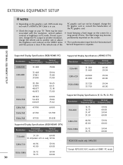
... the screen. If noise is present, change the PC output to another resolution, change the PC graphic card or consult the manufacturer of time. If the refresh rate of the PC graphic card can not be noise associated with the resolution, vertical pattern, contrast or brightness in PC mode. The fixed image may be changed, change the refresh rate to DVI Cable is in HDMI1-PC mode. EXTERNAL EQUIPMENT SETUP Supported Display Specifications (RGB...
... the screen. If noise is present, change the PC output to another resolution, change the PC graphic card or consult the manufacturer of time. If the refresh rate of the PC graphic card can not be noise associated with the resolution, vertical pattern, contrast or brightness in PC mode. The fixed image may be changed, change the refresh rate to DVI Cable is in HDMI1-PC mode. EXTERNAL EQUIPMENT SETUP Supported Display Specifications (RGB...

Owners Manual
Page 77
INITIALIZING (RESET TO ORIGINAL FACTORY SETTINGS) This function operates in current mode. XGA Mode Reset SETUP Auto config. AUDIO XGA Mode TIME Reset G OPTION SCREEN LOCK 1 To set 23 SCREEN ADJUSTMENT 73 SETUP VIDEO AUDIO TIME OPTION SCREEN LOCK Auto config. To initialize the adjusted value. 1 Press the M E N U button and then use D or E or or button to select the SCREEN menu. 2 Press the G or button and then use D or E or or button to select Reset. 3 Press the G or button. VIDEO Manual config. Manual config.
INITIALIZING (RESET TO ORIGINAL FACTORY SETTINGS) This function operates in current mode. XGA Mode Reset SETUP Auto config. AUDIO XGA Mode TIME Reset G OPTION SCREEN LOCK 1 To set 23 SCREEN ADJUSTMENT 73 SETUP VIDEO AUDIO TIME OPTION SCREEN LOCK Auto config. To initialize the adjusted value. 1 Press the M E N U button and then use D or E or or button to select the SCREEN menu. 2 Press the G or button and then use D or E or or button to select Reset. 3 Press the G or button. VIDEO Manual config. Manual config.
Owners Manual
Page 78
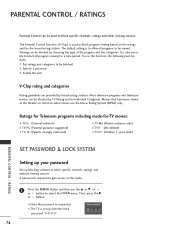
... also possible to block specific channels, ratings, and external viewing sources. To use this menu. 1 Press the MENU button and then use the Movie Rating System (MPAA) only. Ratings for Television programs including made-for a time period. A password is set up blocking schemes to block all programs to block program viewing based on the ratings sent by choosing the type of the program and the categories. Specify a password 3. Movies that have...
... also possible to block specific channels, ratings, and external viewing sources. To use this menu. 1 Press the MENU button and then use the Movie Rating System (MPAA) only. Ratings for Television programs including made-for a time period. A password is set up blocking schemes to block all programs to block program viewing based on the ratings sent by choosing the type of the program and the categories. Specify a password 3. Movies that have...

Operation Guide
Page 2
... the TV Connect cable to the Owner's Manual for the TV you will need to know how to the separately-supplied TV Owner's Manual (Users guide). The remote shown in the menu. Cloning is only possible when the signal source is the commercial mode setup guide only. The installer remote must have problems. Refer to TV MPI Jack and follow on screen instructions Status Indicator MPI • green • red Color Reset battery ok battery low Blink pattern • slow power on no...
... the TV Connect cable to the Owner's Manual for the TV you will need to know how to the separately-supplied TV Owner's Manual (Users guide). The remote shown in the menu. Cloning is only possible when the signal source is the commercial mode setup guide only. The installer remote must have problems. Refer to TV MPI Jack and follow on screen instructions Status Indicator MPI • green • red Color Reset battery ok battery low Blink pattern • slow power on no...

Operation Guide
Page 5
... own SAP setting. • Digital channels will display program information on the next page to access the Installer menus. TV INPUT/INPUT Select available input sources. CHANNEL UP/DOWN/PAGE Selects available channels found with the MODE key. Dash for VCR recording: Once, Regularly, Weekly, Off. ("RECORD" button only). Switches video window lock/unlock in DVD mode.) Set up the main menu to default audio language with a power off . EZ PIC Selects the factory preset picture appropriate...
... own SAP setting. • Digital channels will display program information on the next page to access the Installer menus. TV INPUT/INPUT Select available input sources. CHANNEL UP/DOWN/PAGE Selects available channels found with the MODE key. Dash for VCR recording: Once, Regularly, Weekly, Off. ("RECORD" button only). Switches video window lock/unlock in DVD mode.) Set up the main menu to default audio language with a power off . EZ PIC Selects the factory preset picture appropriate...

Operation Guide
Page 7
... Connections/Learning Setup Connections for the LT2002 Clone Programmer to Learn the TV Master TV Setup Antenna or CATV Ferrite Core (TDK, ZCAT 2035-0930) Connect cable to TV MPI Jack and follow on screen instructions Status Indicator MPI • green • red Color Reset battery ok battery low Blink pattern • slow power on no communications • heartbeat power on the TV screen, see above to connect the Clone to a Master TV TV display panel. THE...
... Connections/Learning Setup Connections for the LT2002 Clone Programmer to Learn the TV Master TV Setup Antenna or CATV Ferrite Core (TDK, ZCAT 2035-0930) Connect cable to TV MPI Jack and follow on screen instructions Status Indicator MPI • green • red Color Reset battery ok battery low Blink pattern • slow power on no communications • heartbeat power on the TV screen, see above to connect the Clone to a Master TV TV display panel. THE...

Operation Guide
Page 15
... channel at power up TV to customize each TV's RJP setup based on the RJP's audio hierarchical priority. See item 96 Default Aspect Ratio above. 116 - VIDEO MUTE EN (Video Mute Enable) Set to 1 will be heard. 6 = Series 200 RJP, DVI Mode Enables RJP when an HDMI cable is expected from HDMI. Set to 1 to 1 for normal. Set to reload presets for Virtual Channel scan. 104 - RJP AVAILABLE (Remote Jack Pack Available) 0 = Remote...
... channel at power up TV to customize each TV's RJP setup based on the RJP's audio hierarchical priority. See item 96 Default Aspect Ratio above. 116 - VIDEO MUTE EN (Video Mute Enable) Set to 1 will be heard. 6 = Series 200 RJP, DVI Mode Enables RJP when an HDMI cable is expected from HDMI. Set to 1 to 1 for normal. Set to reload presets for Virtual Channel scan. 104 - RJP AVAILABLE (Remote Jack Pack Available) 0 = Remote...

Operation Guide
Page 22
... TV mode. -Use Mode key to other problems not caused by the TV, refer to select TV; device. -Try another channel. -Adjust Installer menu settings. (See Owners manual) (See Owners manual) 10 ~ 15 Erratic Operation Installer menu setup. • Wrong Installer menu settings. -Adjust Installer menu settings as required. 10 ~ 15 Remote Control Remote doesn't work. • Remote not in room. -Dim room light. • Wrong Installer remote control. -Requires compatible Installer remote, contact your LG dealer. 2 Picture Reception Normal picture, poor or no sound. • Audio...
... TV mode. -Use Mode key to other problems not caused by the TV, refer to select TV; device. -Try another channel. -Adjust Installer menu settings. (See Owners manual) (See Owners manual) 10 ~ 15 Erratic Operation Installer menu setup. • Wrong Installer menu settings. -Adjust Installer menu settings as required. 10 ~ 15 Remote Control Remote doesn't work. • Remote not in room. -Dim room light. • Wrong Installer remote control. -Requires compatible Installer remote, contact your LG dealer. 2 Picture Reception Normal picture, poor or no sound. • Audio...

Operation Guide
Page 23
... Analog channel signal source. - cord not connected. • TV not turned on clone programmer, redo teach/learn. (Teach/Learn should only scan channels once. Clone not working. • Clone programmer problem. Clone time disappeared. • Batteries were removed. - New Setup not present. • TV not reset. - Use with earlier TV sets may be used before the 221-01006-04 have a limited screen display capability. LED does not blink. • M.P.I . Connect M.P.I . Connect TV to Clone Programmer. - Possible Solution(s) - Install...
... Analog channel signal source. - cord not connected. • TV not turned on clone programmer, redo teach/learn. (Teach/Learn should only scan channels once. Clone not working. • Clone programmer problem. Clone time disappeared. • Batteries were removed. - New Setup not present. • TV not reset. - Use with earlier TV sets may be used before the 221-01006-04 have a limited screen display capability. LED does not blink. • M.P.I . Connect M.P.I . Connect TV to Clone Programmer. - Possible Solution(s) - Install...

Operation Guide
Page 27
... television signals transmitted digitally. DELETED Lets you remove channels from the list that connects a twowire 300 ohm antenna to a tuner device that comes from a television, CD player, VCR, DVD, or other end. Refers to television signals that have to be using three separate colors: Red, Green, and Blue. RGB (Red, Green, Blue) Connection input or output port available for producing a video image using an antenna. Refers to the descrambler box cable subscribers use to www.atsc.org for transporting three-color video signals. XDS Extended Data Service: Additional program...
... television signals transmitted digitally. DELETED Lets you remove channels from the list that connects a twowire 300 ohm antenna to a tuner device that comes from a television, CD player, VCR, DVD, or other end. Refers to television signals that have to be using three separate colors: Red, Green, and Blue. RGB (Red, Green, Blue) Connection input or output port available for producing a video image using an antenna. Refers to the descrambler box cable subscribers use to www.atsc.org for transporting three-color video signals. XDS Extended Data Service: Additional program...


