Owner's Manual (English)
Page 1
... in Korea As an ENERGY STAR Partner LGE U. Record model number and serial number of the set of power-saving guidelines issued by the U.S. LCD TV MODELS: 32LC2D 32LC2DU 37LC2D 42LC2D PLASMA TV MODELS: 42PC3D 42PC3DC 42PC3DV 50PC3D 60PC1D 60PC1DC OWNER'S MANUAL Internet Home Page : http://www.lge.com http://www...
... in Korea As an ENERGY STAR Partner LGE U. Record model number and serial number of the set of power-saving guidelines issued by the U.S. LCD TV MODELS: 32LC2D 32LC2DU 37LC2D 42LC2D PLASMA TV MODELS: 42PC3D 42PC3DC 42PC3DV 50PC3D 60PC1D 60PC1DC OWNER'S MANUAL Internet Home Page : http://www.lge.com http://www...

Owner's Manual (English)
Page 2
...National Electric Code (U.S.A.). This equipment generates, uses and can be connected to the grounding system of the FCC Rules. However, there is : LG Electronics U.S.A., Inc. 1000 Sylvan Avenue, Englewood Cliffs, NJ 07632 Phone: 1-800-243-0000 http://www.lgusa.com 2 REGULATORY INFORMATION This ... are designed to persons. Increase the separation between the equipment and receiver. - Consult the dealer or an experienced radio/TV technician for compliance could void the user's authority to operate the equipment. The lightning flash with the limits for proper ...
...National Electric Code (U.S.A.). This equipment generates, uses and can be connected to the grounding system of the FCC Rules. However, there is : LG Electronics U.S.A., Inc. 1000 Sylvan Avenue, Englewood Cliffs, NJ 07632 Phone: 1-800-243-0000 http://www.lgusa.com 2 REGULATORY INFORMATION This ... are designed to persons. Increase the separation between the equipment and receiver. - Consult the dealer or an experienced radio/TV technician for compliance could void the user's authority to operate the equipment. The lightning flash with the limits for proper ...

Owner's Manual (English)
Page 4
...or moisture, does not operate normally, or has been dropped. 13. that appliance and has no adverse effect on the screen. FOR LCD TV Note - Disposal of this product with the apparatus. The fluorescent lamp used , use of time. DISCONNECTING DEVICE FROM MAINS Main plug is...is turned on the screen, appearing as being twisted, kinked, pinched, closed in this owner's manual to the regulations of mercury. If the TV feels cold to avoid injury from physical or mechanical abuse, such as tiny red, green, or blue spots. Safety Instructions 12. Avoid touching...
...or moisture, does not operate normally, or has been dropped. 13. that appliance and has no adverse effect on the screen. FOR LCD TV Note - Disposal of this product with the apparatus. The fluorescent lamp used , use of time. DISCONNECTING DEVICE FROM MAINS Main plug is...is turned on the screen, appearing as being twisted, kinked, pinched, closed in this owner's manual to the regulations of mercury. If the TV feels cold to avoid injury from physical or mechanical abuse, such as tiny red, green, or blue spots. Safety Instructions 12. Avoid touching...

Owner's Manual (English)
Page 5
... Audio Menu Options 14 15 16~17 18 19~20 20 21~22 23~24 25 25 26~28 Attaching the TV to a wall Desktop Pedestal Installation Basic Connection Antenna or Cable Connection VCR Setup External AV Source Setup DVD Setup HDSTB ...29 29 29 30 31 31 32 33 33 34 35 35~36 37 38 39 40 41 41~42 43 43 Turning on the TV Volume Adjustment Channel Selection On Screen Menus Language Selection On Screen Menus Selection and Adjustment EZ Scan (Channel ... Level Video Reset Audio Language Auto Sound Control(EZ Sound) Manual Sound Control (EZ Sound-User option) Balance TV Speakers On/Off Setup Operation Contents 5
... Audio Menu Options 14 15 16~17 18 19~20 20 21~22 23~24 25 25 26~28 Attaching the TV to a wall Desktop Pedestal Installation Basic Connection Antenna or Cable Connection VCR Setup External AV Source Setup DVD Setup HDSTB ...29 29 29 30 31 31 32 33 33 34 35 35~36 37 38 39 40 41 41~42 43 43 Turning on the TV Volume Adjustment Channel Selection On Screen Menus Language Selection On Screen Menus Selection and Adjustment EZ Scan (Channel ... Level Video Reset Audio Language Auto Sound Control(EZ Sound) Manual Sound Control (EZ Sound-User option) Balance TV Speakers On/Off Setup Operation Contents 5

Owner's Manual (English)
Page 7
... TIMER EXIT VOL MUTE CC PAGE INFO 1 4 7 2 FAV PAGE CH 5 EZ ADJUST PIC EZ APM SOUND 0 SAP 8 9 FLASHBK 6 3 FREEZE TV INPUT 1.5V DAY - Please be cautious of that the following accessories are included with ferrite cores to maintain standard compliance for the product exterior if... product. 7 If any accessory is stain or fingerprint on a cushioned surface that will protect product and screen from where you purchased the product. TV AUDIO PO CABMLEODDEVD 1.5VMENU GUIDE ENTER STB DAY+ RATIO TIMER EXIT VOL MUTE CC PAGE INFO 1 FAV 4 7 2 PAGE CH 5 EZ...
... TIMER EXIT VOL MUTE CC PAGE INFO 1 4 7 2 FAV PAGE CH 5 EZ ADJUST PIC EZ APM SOUND 0 SAP 8 9 FLASHBK 6 3 FREEZE TV INPUT 1.5V DAY - Please be cautious of that the following accessories are included with ferrite cores to maintain standard compliance for the product exterior if... product. 7 If any accessory is stain or fingerprint on a cushioned surface that will protect product and screen from where you purchased the product. TV AUDIO PO CABMLEODDEVD 1.5VMENU GUIDE ENTER STB DAY+ RATIO TIMER EXIT VOL MUTE CC PAGE INFO 1 FAV 4 7 2 PAGE CH 5 EZ...

Owner's Manual (English)
Page 8
... Indicator Illuminates red in standby mode. • illuminates green when the set is switched on . This picture shown below may be somewhat different from your TV. 42PC3D/3DC/3DV, 50PC3D Remote Control Sensor Power/Standby Indicator • illuminates red in standby mode. This is switched on . 8 ENTER ENTER POWER INPUT Button...
... Indicator Illuminates red in standby mode. • illuminates green when the set is switched on . This picture shown below may be somewhat different from your TV. 42PC3D/3DC/3DV, 50PC3D Remote Control Sensor Power/Standby Indicator • illuminates red in standby mode. This is switched on . 8 ENTER ENTER POWER INPUT Button...

Owner's Manual (English)
Page 9
...Or DVI (VIDEO)signal to the 1(DVI) port with AC power. Caution: Never attempt to the appropriate input port. 2 AV OUT Connect a second TV or monitor. 3 AV (Audio/Video) IN 1 Connect audio/video output from various types of equipment. AUDIO COMPONENT IN AV OUT AV IN 1 ...3DC/3DV, 50PC3D, 60PC1D/1DC) - S-VIDEO VIDEO ( ) AUDIO 9 S-VIDEO VIDEO ( ) AUDIO Connect cable signals to these ports do notVwIDEOork. 8 Remote Control Port Connect your TV. COMPONENT IN AV OUT AV IN 1 COMPONENT IN AV OUT AV IN 1 10 SERVICE 6 4 ANTENNA/ CABLE IN HDMI IN 2 1(DVI) 7 RGB IN 5 8 (CONTROL...
...Or DVI (VIDEO)signal to the 1(DVI) port with AC power. Caution: Never attempt to the appropriate input port. 2 AV OUT Connect a second TV or monitor. 3 AV (Audio/Video) IN 1 Connect audio/video output from various types of equipment. AUDIO COMPONENT IN AV OUT AV IN 1 ...3DC/3DV, 50PC3D, 60PC1D/1DC) - S-VIDEO VIDEO ( ) AUDIO 9 S-VIDEO VIDEO ( ) AUDIO Connect cable signals to these ports do notVwIDEOork. 8 Remote Control Port Connect your TV. COMPONENT IN AV OUT AV IN 1 COMPONENT IN AV OUT AV IN 1 10 SERVICE 6 4 ANTENNA/ CABLE IN HDMI IN 2 1(DVI) 7 RGB IN 5 8 (CONTROL...

Owner's Manual (English)
Page 10
... Control Sensor Power/Standby Indicator • illuminates red in standby mode. • illuminates green when the set is a simplified representation of front panel. - The TV can be somewhat different from your TV. R 10 This is switched on its stand 30° to the left or right to provide the optimum viewing angle.
... Control Sensor Power/Standby Indicator • illuminates red in standby mode. • illuminates green when the set is a simplified representation of front panel. - The TV can be somewhat different from your TV. R 10 This is switched on its stand 30° to the left or right to provide the optimum viewing angle.

Owner's Manual (English)
Page 11
...toS-VIDEO VIDEO AV IN 1 7 RGB IN (PC) ( ) AUDIO Connect the monitor output from a PC to the appropriate input port. 2 AV OUT Connect a second TV or monitor. 3 AV (Audio/Video) IN 1 Connect audio/video output from a video device. S-VIDEO Connect S-Video out from an S-VIDEO device. 4 ANTENNA/CABLE IN... Connect over-the air signals to these ports do not work. 8 Remote Control Port Connect your TV. Caution: Never attempt to operate the TV on a PC. 10 SERVICE 11 Power Cord Socket For operation with a DVI to the 1(DVI) port with AC power. Note: ...
...toS-VIDEO VIDEO AV IN 1 7 RGB IN (PC) ( ) AUDIO Connect the monitor output from a PC to the appropriate input port. 2 AV OUT Connect a second TV or monitor. 3 AV (Audio/Video) IN 1 Connect audio/video output from a video device. S-VIDEO Connect S-Video out from an S-VIDEO device. 4 ANTENNA/CABLE IN... Connect over-the air signals to these ports do not work. 8 Remote Control Port Connect your TV. Caution: Never attempt to operate the TV on a PC. 10 SERVICE 11 Power Cord Socket For operation with a DVI to the 1(DVI) port with AC power. Note: ...

Owner's Manual (English)
Page 12
...1-2, RGB, HDMI1/DVI and HDMI2 mode. 12 It turns to operate an external device. EXIT Clears all on mode. Not available in regular sequence: TV, AV1-2, Component 1-2, RGB-PC, HDMI1/DVI or HDMI2. (AV 1-2, Component 1-2, RGB-PC , HDMI1/DVI or HDMI2 input sources are linked automatically,... only if these are connected.) MODE Selects the remote operating mode: TV, DVD, VCR, AUDIO, CABLE, or STB. MENU BRIGHT + ENTER EXIT TIMER RATIO INFO VOL MUTE FAV CH 1 2 3 4 5 6 7 8 9 0 FLASHBK EZ ...
...1-2, RGB, HDMI1/DVI and HDMI2 mode. 12 It turns to operate an external device. EXIT Clears all on mode. Not available in regular sequence: TV, AV1-2, Component 1-2, RGB-PC, HDMI1/DVI or HDMI2. (AV 1-2, Component 1-2, RGB-PC , HDMI1/DVI or HDMI2 input sources are linked automatically,... only if these are connected.) MODE Selects the remote operating mode: TV, DVD, VCR, AUDIO, CABLE, or STB. MENU BRIGHT + ENTER EXIT TIMER RATIO INFO VOL MUTE FAV CH 1 2 3 4 5 6 7 8 9 0 FLASHBK EZ ...

Owner's Manual (English)
Page 13
... available channels found with EZ scan and Manual scan. NUMBER BUTTONS - (DASH) Used to enter a program number for multiple program channels such as 2-1, 2-2,etc. Introduction TV INPUT POWER TV AUDIO DVD MODE CABLE INPUT VCR STB BRIGHT -
... available channels found with EZ scan and Manual scan. NUMBER BUTTONS - (DASH) Used to enter a program number for multiple program channels such as 2-1, 2-2,etc. Introduction TV INPUT POWER TV AUDIO DVD MODE CABLE INPUT VCR STB BRIGHT -

Owner's Manual (English)
Page 14
...the wall to the holes in a forward direction, potentially causing injury or damaging the product. MENU BRIGHT + ENTER EXIT TIMER RATIO INFO TV INPUT POWER TV AUDIO DVD MODE CABLE INPUT VCR STB BRIGHT - I Dispose of used batteries with new ones. I Use a remote control up the.... Don't mix old or used batteries in the eye-bolts position, loosen the bolts. TV INPUT POWER TV AUDIO DVD MODE CABLE INPUT VCR STB BRIGHT - ATTACHING THE TV TO A WALL We recommend that the TV be attached to 7 meters distance and 30 degree (left/right) within the receiving unit scope...
...the wall to the holes in a forward direction, potentially causing injury or damaging the product. MENU BRIGHT + ENTER EXIT TIMER RATIO INFO TV INPUT POWER TV AUDIO DVD MODE CABLE INPUT VCR STB BRIGHT - I Dispose of used batteries with new ones. I Use a remote control up the.... Don't mix old or used batteries in the eye-bolts position, loosen the bolts. TV INPUT POWER TV AUDIO DVD MODE CABLE INPUT VCR STB BRIGHT - ATTACHING THE TV TO A WALL We recommend that the TV be attached to 7 meters distance and 30 degree (left/right) within the receiving unit scope...

Owner's Manual (English)
Page 15
.... Do not try to prevent possible electric shock. Installation Installation DESKTOP PEDESTAL INSTALLATION For proper ventilation, allow a clearance of 4inches on each side from your TV.
.... Do not try to prevent possible electric shock. Installation Installation DESKTOP PEDESTAL INSTALLATION For proper ventilation, allow a clearance of 4inches on each side from your TV.

Owner's Manual (English)
Page 18
... area to tighten. IDfIGtIThOALUeATUDaIOntenSn-VIaDEOisVIDnEOot ( ) inAUsDtIOalled properly, contact your dealer for outdoor antenna) Analog and Digital TV signals provided on cable Cable TV Wall Jack RF Coaxial Wire (75 ohm) Bronze Wire Be careful not to bend the bronze wire when connecting... the antenna. Outdoor Antenna Single-family Dwellings /Houses (Connect to be split for two TV's, install a "2-Way Signal Splitter" • in the connections. Analog and DTV signals provided on antenna - Installation External Equipment...
... area to tighten. IDfIGtIThOALUeATUDaIOntenSn-VIaDEOisVIDnEOot ( ) inAUsDtIOalled properly, contact your dealer for outdoor antenna) Analog and Digital TV signals provided on cable Cable TV Wall Jack RF Coaxial Wire (75 ohm) Bronze Wire Be careful not to bend the bronze wire when connecting... the antenna. Outdoor Antenna Single-family Dwellings /Houses (Connect to be split for two TV's, install a "2-Way Signal Splitter" • in the connections. Analog and DTV signals provided on antenna - Installation External Equipment...

Owner's Manual (English)
Page 19
... 34 VIDEO AUDIO ANT OUT 1 OPTICAL DIGITAL AUDIO ( ) VIDEOS-VIDEO VIDEOAUDIO AUDIO OUT 1 Connect the AUDIO/VIDEO jacks between the VCR and TV. - If connected to the VCR owner's manual.) 3 Select AV1 input source using the INPUT button on the screen. VIDEO AUDIO OPTICAL DIGITAL ... ( ) VIDAEUODIO AUDIO 19 COMPONENT IN AV OUT AV IN 1 COMPONENT IN AV OUT A To avoid picture noise (interference), leave an adequate distance between TV and VCR. When connecting with an antenna 2 VCR ANT IN ANT OUT S-VIDEO OUT OUTPUT SWITCH 34 (R) AUDIO (L) IN VIDEO SERVICE 1 RGB IN...
... 34 VIDEO AUDIO ANT OUT 1 OPTICAL DIGITAL AUDIO ( ) VIDEOS-VIDEO VIDEOAUDIO AUDIO OUT 1 Connect the AUDIO/VIDEO jacks between the VCR and TV. - If connected to the VCR owner's manual.) 3 Select AV1 input source using the INPUT button on the screen. VIDEO AUDIO OPTICAL DIGITAL ... ( ) VIDAEUODIO AUDIO 19 COMPONENT IN AV OUT AV IN 1 COMPONENT IN AV OUT A To avoid picture noise (interference), leave an adequate distance between TV and VCR. When connecting with an antenna 2 VCR ANT IN ANT OUT S-VIDEO OUT OUTPUT SWITCH 34 (R) AUDIO (L) IN VIDEO SERVICE 1 RGB IN...
Owner's Manual (English)
Page 20
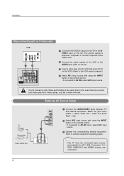
...INPUT button on the remote control. - External AV Source Setup Camcorder Video Game Set 1 L AUDIO R VIDEO 1 Connect the AUDIO/VIDEO jacks between TV and external equipment. Match the jack colors (Video = yellow, Audio Left = white, and Audio Right = red). 2 Select AV2 input source with...The picture quality is improved; If connected to AV IN2, select AV2 input source. Refer to external equipment operating guide. • This TV finds the connected input sources automatically for AV1, AV2, Component 1-2, RGB, HDMI1/DVI and HDMI2 sources are connected. 20 Installation COMPONENT ...
...INPUT button on the remote control. - External AV Source Setup Camcorder Video Game Set 1 L AUDIO R VIDEO 1 Connect the AUDIO/VIDEO jacks between TV and external equipment. Match the jack colors (Video = yellow, Audio Left = white, and Audio Right = red). 2 Select AV2 input source with...The picture quality is improved; If connected to AV IN2, select AV2 input source. Refer to external equipment operating guide. • This TV finds the connected input sources automatically for AV1, AV2, Component 1-2, RGB, HDMI1/DVI and HDMI2 sources are connected. 20 Installation COMPONENT ...
Owner's Manual (English)
Page 21
VIDEO AUDIO COMPONENT IN AV OUT AV IN 1 OPTICAL DIGITAL AUDIO OUT S-VIDEO VIDEO ( ) AUDIO • TV can receive the video and audio signal simultaneously with using the INPUT button on the remote control. 3 Refer to the DVD player's manual for operating ...
VIDEO AUDIO COMPONENT IN AV OUT AV IN 1 OPTICAL DIGITAL AUDIO OUT S-VIDEO VIDEO ( ) AUDIO • TV can receive the video and audio signal simultaneously with using the INPUT button on the remote control. 3 Refer to the DVD player's manual for operating ...

Owner's Manual (English)
Page 22
Component ports on the TV Video output ports on the remote control. - Installation When connecting with a component cable DVD B R (R) AUDIO (L) 1 2 VIDEO AUDIO ANTENNA/ CABLE IN HDMI / DVI IN COMPONENT IN 1 ...
Component ports on the TV Video output ports on the remote control. - Installation When connecting with a component cable DVD B R (R) AUDIO (L) 1 2 VIDEO AUDIO ANTENNA/ CABLE IN HDMI / DVI IN COMPONENT IN 1 ...
Owner's Manual (English)
Page 23
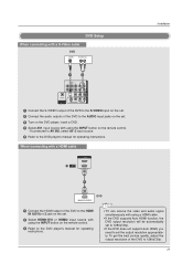
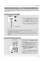
...Signal Component1/2 480i Yes 480p/720p/1080i Yes HDMI1/DVI, HDMI2 No Yes RGB IN (PC) AUDIO IN REMOTE (RGB/DVI) CONTROL IN 23 This TV can receive the video and audio signal simultaneously using a HDMI cable. • If the digital set-top box supports Auto HDMI function, output resolution of...box.) HDMI-DTV OUTPUT Digital Set-top Box COMPONENT IN AV OUT AV IN 1 RGB IN (PC) AUDIO IN REMOTE (RGB/DVI) CONTROL IN • TV can receive Digital Over-the-air/Cable signals without an external digital set . However, if you need to COMPONENT IN 2, select Component 2 input source. When...
...Signal Component1/2 480i Yes 480p/720p/1080i Yes HDMI1/DVI, HDMI2 No Yes RGB IN (PC) AUDIO IN REMOTE (RGB/DVI) CONTROL IN 23 This TV can receive the video and audio signal simultaneously using a HDMI cable. • If the digital set-top box supports Auto HDMI function, output resolution of...box.) HDMI-DTV OUTPUT Digital Set-top Box COMPONENT IN AV OUT AV IN 1 RGB IN (PC) AUDIO IN REMOTE (RGB/DVI) CONTROL IN • TV can receive Digital Over-the-air/Cable signals without an external digital set . However, if you need to COMPONENT IN 2, select Component 2 input source. When...

Owner's Manual (English)
Page 25
... We recommend to use the video and audio output jacks for operation. Looking at the laser beam may damage your vision. 25 Send the TV's audio to p.43) CAUTION Do not look into the optical output port. Digital Audio Output - Installation AV Out Setup - When connecting with... external audio equipments, such as amplifiers or speakers, please turn the TV speakers off. (Refer to external audio equipment (stereo system) via the Digital Audio Output Optical port. COMPONENT IN AV OUT AV IN 1 ...
... We recommend to use the video and audio output jacks for operation. Looking at the laser beam may damage your vision. 25 Send the TV's audio to p.43) CAUTION Do not look into the optical output port. Digital Audio Output - Installation AV Out Setup - When connecting with... external audio equipments, such as amplifiers or speakers, please turn the TV speakers off. (Refer to external audio equipment (stereo system) via the Digital Audio Output Optical port. COMPONENT IN AV OUT AV IN 1 ...

