User Manual
Page 1
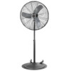
... wire only. Please refer to National Electric Code (NEC) Article 500 or applicable state or local codes or standards relating to the electri- CAUTION: BECAUSE OF THE SIZE AND WEIGHT OF THIS FAN, MAKE SURE ALL PARTS ARE COMPLETELY ASSEMBLED ACCORDING TO INSTRUCTIONS. E 8/10 1 5084445 30" INDUSTRIAL GRADE OSCILLATING PEDESTAL FAN WITH WHEELS Model 3138 READ AND SAVE THESE INSTRUCTIONS READ CAREFULLY BEFORE ATTEMPTING TO ASSEMBLE, INSTALL, OPERATE...
... wire only. Please refer to National Electric Code (NEC) Article 500 or applicable state or local codes or standards relating to the electri- CAUTION: BECAUSE OF THE SIZE AND WEIGHT OF THIS FAN, MAKE SURE ALL PARTS ARE COMPLETELY ASSEMBLED ACCORDING TO INSTRUCTIONS. E 8/10 1 5084445 30" INDUSTRIAL GRADE OSCILLATING PEDESTAL FAN WITH WHEELS Model 3138 READ AND SAVE THESE INSTRUCTIONS READ CAREFULLY BEFORE ATTEMPTING TO ASSEMBLE, INSTALL, OPERATE...

User Manual
Page 2
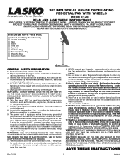
... Bolt (3/8-16 X 1") Split Lockwasher (3/8") Hex Nut (3/8-16) Mounting Flange Carriage Bolt (5/16-18 X 1") Split Lockwasher (5/16") Hex Nut (5/16-18) MOTOR HARDWARE BAG (1) Hex Bolt (1/2-13 X 1") (1) Split Lockwasher (1/2") (1) Hex Nut (1/2-13) (1) Carriage Bolt (1/4-20 X 1 5/8") (1) Lockwasher (1/4" Internal Tooth) (2) Flatwashers (1/4") (1) Adjustable Knob (6) Hex Head Screws (10-32 X 5/16") (1) Pull Cord Hex Bolt (1/2-13 X 1") Split Lockwasher (1/2") Hex...
... Bolt (3/8-16 X 1") Split Lockwasher (3/8") Hex Nut (3/8-16) Mounting Flange Carriage Bolt (5/16-18 X 1") Split Lockwasher (5/16") Hex Nut (5/16-18) MOTOR HARDWARE BAG (1) Hex Bolt (1/2-13 X 1") (1) Split Lockwasher (1/2") (1) Hex Nut (1/2-13) (1) Carriage Bolt (1/4-20 X 1 5/8") (1) Lockwasher (1/4" Internal Tooth) (2) Flatwashers (1/4") (1) Adjustable Knob (6) Hex Head Screws (10-32 X 5/16") (1) Pull Cord Hex Bolt (1/2-13 X 1") Split Lockwasher (1/2") Hex...

User Manual
Page 3
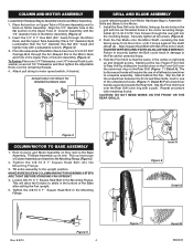
... 3/8-16 Hex Nut. Fit Mounting Flange through Mounting Flange and Base. 4. Repeat above procedure with other Wheel Assembly. Remove Wheel Assemblies from Hardware Bag "D". 2. E 8/10 Figure 3 3 5084445 Insert (4) 3/8-16 X 1" Carriage Bolts through large hole in center of Base...Bolt Mounting Flange Hex Nut (4) Figure 1 WHEELS TO BASE ASSEMBLY Locate Hardware Bag "D" to Assemble Wheels to Assemble Base. (Figure 1) 1. Tilt Base and secure one Wheel Assembly on floor. 2. Figure 2 CORRECT INCORRECT Rev. Place Base on Base location as shown. 4. BASE ASSEMBLY Locate Hardware...
... 3/8-16 Hex Nut. Fit Mounting Flange through Mounting Flange and Base. 4. Repeat above procedure with other Wheel Assembly. Remove Wheel Assemblies from Hardware Bag "D". 2. E 8/10 Figure 3 3 5084445 Insert (4) 3/8-16 X 1" Carriage Bolts through large hole in center of Base...Bolt Mounting Flange Hex Nut (4) Figure 1 WHEELS TO BASE ASSEMBLY Locate Hardware Bag "D" to Assemble Wheels to Assemble Base. (Figure 1) 1. Tilt Base and secure one Wheel Assembly on floor. 2. Figure 2 CORRECT INCORRECT Rev. Place Base on Base location as shown. 4. BASE ASSEMBLY Locate Hardware...
User Manual
Page 4
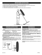
... the Motor Neck, and the Upper Tube Assembly. Actual motor not shown for detailed hardware view. GRILL AND BLADE ASSEMBLY Locate remaining parts from the motor, until it stops against the shaft (Inset A) . Install (6) 10-32 X 5/16" Hex Screws through the rear grill into the Mounting Flange....ring with a adjustable wrench. (Figure 4) 3. MAKE SURE BOLTS IN COLUMN AND MOTOR ASSEMBLY STEPS ARE TIGHT BEFORE STANDING FAN UPRIGHT. 4. Hold the Front Grill so that the name, in the Upper Pipe of a flathead screwdriver to motor speed switch, if desired. CAUTION: DO NOT BEND WIRES...
... the Motor Neck, and the Upper Tube Assembly. Actual motor not shown for detailed hardware view. GRILL AND BLADE ASSEMBLY Locate remaining parts from the motor, until it stops against the shaft (Inset A) . Install (6) 10-32 X 5/16" Hex Screws through the rear grill into the Mounting Flange....ring with a adjustable wrench. (Figure 4) 3. MAKE SURE BOLTS IN COLUMN AND MOTOR ASSEMBLY STEPS ARE TIGHT BEFORE STANDING FAN UPRIGHT. 4. Hold the Front Grill so that the name, in the Upper Pipe of a flathead screwdriver to motor speed switch, if desired. CAUTION: DO NOT BEND WIRES...
User Manual
Page 5
... the oscillation knob in the motor is in a clean and dry place. 3. lect desired operating speed with these instructions, in the locked down oscillation knob on motor housing to make certain to secure the head assembly. 3. WARNING: DO NOT IMMERSE FAN IN WATER! STORAGE: Store the Fan, with pull cord on column collar (turn counterclockwise). Cam Gear (Inset A) 1. 2. make fan head move Fan while blade is...
... the oscillation knob in the motor is in a clean and dry place. 3. lect desired operating speed with these instructions, in the locked down oscillation knob on motor housing to make certain to secure the head assembly. 3. WARNING: DO NOT IMMERSE FAN IN WATER! STORAGE: Store the Fan, with pull cord on column collar (turn counterclockwise). Cam Gear (Inset A) 1. 2. make fan head move Fan while blade is...

User Manual
Page 6
... service questions, and replacement parts. Customer Service Dept., 820 Lincoln Ave., West Chester, PA 19380 (Please do not allow limitations on the underside of the product and lasts for one (1) year from state to state and province to assist you specific legal rights. HOW LONG THIS WARRANTY LASTS: This warranty extends only to the original purchaser of your model number...
... service questions, and replacement parts. Customer Service Dept., 820 Lincoln Ave., West Chester, PA 19380 (Please do not allow limitations on the underside of the product and lasts for one (1) year from state to state and province to assist you specific legal rights. HOW LONG THIS WARRANTY LASTS: This warranty extends only to the original purchaser of your model number...


