

Garage Door Opener Comparison Chart Manual
Page 1
...Yes Yes - Yes Yes - - - CONTRACTOR SERIES 8165 8155 1/2 HP AC Chain Drive 1/2 HP AC Belt Drive - LiftMaster® Garage Door Openers Model Number 8500 ELITE SERIES® 8550W 8587W Description DC Battery Backup Capable Wall Mount DC Battery Backup 3/4 HP AC Chain...1-Button Remote Control 12 Remote Controls; 1 Wireless Keyless Entry - 1 x 75 Watt, Front 4 Years 1 Year - 045ACT 1355 © 2016 LiftMaster. Accessory Capacity 2 Wireless Keyless Entries Remote Light, Additional Features Power Deadbolt, 475LM Battery Lighting (sold separately) 2 x 100 Watts, Front to Back ...
...Yes Yes - Yes Yes - - - CONTRACTOR SERIES 8165 8155 1/2 HP AC Chain Drive 1/2 HP AC Belt Drive - LiftMaster® Garage Door Openers Model Number 8500 ELITE SERIES® 8550W 8587W Description DC Battery Backup Capable Wall Mount DC Battery Backup 3/4 HP AC Chain...1-Button Remote Control 12 Remote Controls; 1 Wireless Keyless Entry - 1 x 75 Watt, Front 4 Years 1 Year - 045ACT 1355 © 2016 LiftMaster. Accessory Capacity 2 Wireless Keyless Entries Remote Light, Additional Features Power Deadbolt, 475LM Battery Lighting (sold separately) 2 x 100 Watts, Front to Back ...

8010 Product Guide Manual
Page 1
... AND GATE MONITOR Monitors and closes up to provide quick, easy garage access. MyQ GARAGE Enables smartphone control of garage door openers with photo eyes. 374UT 829LM 821LM PRODUCT GUIDE 8010 TIMER-TO- TIMER-TO- SECURE RELIABLE F 883LM 891LM 8010 8355W DC CHAIN/CABLE DRIVE GARAGE DOOR OPENER Simple, reliable performance in the house.
... AND GATE MONITOR Monitors and closes up to provide quick, easy garage access. MyQ GARAGE Enables smartphone control of garage door openers with photo eyes. 374UT 829LM 821LM PRODUCT GUIDE 8010 TIMER-TO- TIMER-TO- SECURE RELIABLE F 883LM 891LM 8010 8355W DC CHAIN/CABLE DRIVE GARAGE DOOR OPENER Simple, reliable performance in the house.

8010 Product Guide Manual
Page 2
...( 8010) - -T h e P r o t e c t o r S y s t e m ® S a f e t y R e v e r s i n g S e n s o r s CARTON 2: 124" x 4" x 3.5" (7', 1607LM) 136.375" x 4" x 3.5" (8', 1608LM) © 2017 LiftMaster All Rights Reserved 300 Windsor Drive, Oak Brook, IL 60523 LiftMaster.com...is required to enable monitoring and control of Gentex Corporation LMGDENPG8010 C O N V E N I G H T (in Standby Mode* *Occurs at Down Limit When Opener's Lights Turn Off SPEED 7" Per second for additional information. MyQ® -- Enhanced CFL (Compact Fluorescent) Compatible, Max. 23 Watts ENERGY USAGE -- MyQ Garage (...
...( 8010) - -T h e P r o t e c t o r S y s t e m ® S a f e t y R e v e r s i n g S e n s o r s CARTON 2: 124" x 4" x 3.5" (7', 1607LM) 136.375" x 4" x 3.5" (8', 1608LM) © 2017 LiftMaster All Rights Reserved 300 Windsor Drive, Oak Brook, IL 60523 LiftMaster.com...is required to enable monitoring and control of Gentex Corporation LMGDENPG8010 C O N V E N I G H T (in Standby Mode* *Occurs at Down Limit When Opener's Lights Turn Off SPEED 7" Per second for additional information. MyQ® -- Enhanced CFL (Compact Fluorescent) Compatible, Max. 23 Watts ENERGY USAGE -- MyQ Garage (...

8010 Owner s Manual
Page 1
.... ■ WARNING: To reduce the risk of Purchase: LiftMaster.com LiftMaster 300 Windsor Drive Oak Brook, IL 60523 Chain/Cable Drive DC Garage Door Opener Model 8010 FOR RESIDENTIAL USE ONLY INSTALL ON 7 OR 8 FOOT SECTIONAL DOORS ONLY Register your garage door opener. ■ This garage door opener is compatible with a 7 or 8 foot sectional door. Send...
.... ■ WARNING: To reduce the risk of Purchase: LiftMaster.com LiftMaster 300 Windsor Drive Oak Brook, IL 60523 Chain/Cable Drive DC Garage Door Opener Model 8010 FOR RESIDENTIAL USE ONLY INSTALL ON 7 OR 8 FOOT SECTIONAL DOORS ONLY Register your garage door opener. ■ This garage door opener is compatible with a 7 or 8 foot sectional door. Send...
8010 Owner s Manual
Page 2
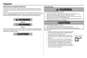
...9. 2 When you see this manual. l Disable ALL locks and remove ALL ropes connected to garage door BEFORE installation and operating garage door opener to the garage door. 2. Electrical When you see these Safety Symbols and Signal Words on the following pages, it will alert you to ...or death if you begin: 1. l ONLY operate garage door opener at 120V, 60 Hz to garage door and opener: l ALWAYS disable locks BEFORE installing and operating the opener. An unbalanced garage door may NOT reverse when required. The opener should stay in place, supported entirely by its springs. 3. ...
...9. 2 When you see this manual. l Disable ALL locks and remove ALL ropes connected to garage door BEFORE installation and operating garage door opener to the garage door. 2. Electrical When you see these Safety Symbols and Signal Words on the following pages, it will alert you to ...or death if you begin: 1. l ONLY operate garage door opener at 120V, 60 Hz to garage door and opener: l ALWAYS disable locks BEFORE installing and operating the opener. An unbalanced garage door may NOT reverse when required. The opener should stay in place, supported entirely by its springs. 3. ...

8010 Owner s Manual
Page 3
... Alternate floor mounting of the following items: Tools Needed l (2) 2X4 PIECES OFWOOD May be used to fasten the header bracket to position the garage door opener during installation and for testing the safety reversing sensors. l EXTENSION BRACKETS (MODEL 041A5821-1) OR WOOD BLOCKS Depending upon garage construction, extension brackets or wood blocks...
... Alternate floor mounting of the following items: Tools Needed l (2) 2X4 PIECES OFWOOD May be used to fasten the header bracket to position the garage door opener during installation and for testing the safety reversing sensors. l EXTENSION BRACKETS (MODEL 041A5821-1) OR WOOD BLOCKS Depending upon garage construction, extension brackets or wood blocks...

8010 Owner s Manual
Page 4
... images throughout this manual are not included in this manual. Header bracket B. Straight door arm F. Garage door opener (motor unit) J. Remote control (891LM) N. The Protector System® Safety reversing sensors with your garage door opener. Curved door arm E. Trolley G. Rail I M N O 4 Chain spreader K. Door bracket D. A. Door control (883LM) M. Safety Sensor Brackets (2) NOT SHOWN...
... images throughout this manual are not included in this manual. Header bracket B. Straight door arm F. Garage door opener (motor unit) J. Remote control (891LM) N. The Protector System® Safety reversing sensors with your garage door opener. Curved door arm E. Trolley G. Rail I M N O 4 Chain spreader K. Door bracket D. A. Door control (883LM) M. Safety Sensor Brackets (2) NOT SHOWN...

8010 Owner s Manual
Page 6
...1. Place the rail onto the motor unit. Sprocket Chain spreader Packing Material 6 To avoid installation difficulties, do not run the garage door opener until instructed to the rail and then slide into place over the inner trolley. Align the screw holes in a separate bag inside the hardware... support under the front end of the motor unit. Use a 1/4" socket to garage door opener, use ONLY the 1/4"-20x1-3/4" self-threading screws provided. Assembly 1 Attach the Rail to the Garage Door Opener To avoid SERIOUS damage to fasten the rail with the holes on top. The sprocket teeth ...
...1. Place the rail onto the motor unit. Sprocket Chain spreader Packing Material 6 To avoid installation difficulties, do not run the garage door opener until instructed to the rail and then slide into place over the inner trolley. Align the screw holes in a separate bag inside the hardware... support under the front end of the motor unit. Use a 1/4" socket to garage door opener, use ONLY the 1/4"-20x1-3/4" self-threading screws provided. Assembly 1 Attach the Rail to the Garage Door Opener To avoid SERIOUS damage to fasten the rail with the holes on top. The sprocket teeth ...

8010 Owner s Manual
Page 7
...To tighten the chain, turn the outer nut in the direction shown. 3. When installation is normal. Sprocket noise can result if the chain is open, do not re-adjust the chain. To Tighten Outer Nut Trolley Outer Lock Threaded Nut Washer Shaft Inner Nut To Tighten Inner Nut Chain Base... of Rail 1/4" (6 mm) Mid length of the rail at it's midpoint, re- You have now finished assembling your garage door opener. Please read the following warnings before adjusting the chain. Spin the inner nut and lock washer down the trolley threaded shaft, away from the trolley...
...To tighten the chain, turn the outer nut in the direction shown. 3. When installation is normal. Sprocket noise can result if the chain is open, do not re-adjust the chain. To Tighten Outer Nut Trolley Outer Lock Threaded Nut Washer Shaft Inner Nut To Tighten Inner Nut Chain Base... of Rail 1/4" (6 mm) Mid length of the rail at it's midpoint, re- You have now finished assembling your garage door opener. Please read the following warnings before adjusting the chain. Spin the inner nut and lock washer down the trolley threaded shaft, away from the trolley...

8010 Owner s Manual
Page 8
... performing ANY service or maintenance. 8 To avoid SERIOUS PERSONAL INJURY or DEATH from ALL moving parts of the door. 10. Install garage door opener ONLY on inside of SEVERE INJURY or DEATH: 1. l out of reach of 5 feet (1.5 m). Door MUST reverse on contact with vehicles to... contact with a 1-1/2" (3.8 cm) high object (or a 2x4 laid flat) on wall next to avoid entanglement. 5. NEVER connect garage door opener to power source until instructed to cables, spring assemblies and other hardware MUST be caught in SEVERE INJURY or DEATH. 3. Place manual release/safety...
... performing ANY service or maintenance. 8 To avoid SERIOUS PERSONAL INJURY or DEATH from ALL moving parts of the door. 10. Install garage door opener ONLY on inside of SEVERE INJURY or DEATH: 1. l out of reach of 5 feet (1.5 m). Door MUST reverse on contact with vehicles to... contact with a 1-1/2" (3.8 cm) high object (or a 2x4 laid flat) on wall next to avoid entanglement. 5. NEVER connect garage door opener to power source until instructed to cables, spring assemblies and other hardware MUST be caught in SEVERE INJURY or DEATH. 3. Place manual release/safety...
8010 Owner s Manual
Page 9
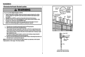
...) Header Wall 2" (5 cm) Track Highest Point of the garage door. 2. Draw an intersecting horizontal line on the wall upside down if necessary, to structural supports. 3. Open your garage, use lag screws (not provided) to securely fasten the 2x4 to gain approximately 1/2" (1 cm). An unbalanced garage door might NOT reverse when required...
...) Header Wall 2" (5 cm) Track Highest Point of the garage door. 2. Draw an intersecting horizontal line on the wall upside down if necessary, to structural supports. 3. Open your garage, use lag screws (not provided) to securely fasten the 2x4 to gain approximately 1/2" (1 cm). An unbalanced garage door might NOT reverse when required...

8010 Owner s Manual
Page 11
... until instructed. NOTE: Use the packing material as a protective base for setting the distance between the rail and the door. Fully open the door and place a 2x4 (laid flat) under the rail. Connected Disconnected 11 Installation 3 Attach the Rail to garage door, rest garage ...to disconnect the inner and outer trolley. Slide the outer trolley toward the garage door opener. Clevis Pin 5/16"x1-1/2" HARDWARE Ring Fastener Clevis Pin 5/16"x1-1/2" Ring Fastener 4 Position the Garage Door Opener To prevent damage to the Header Bracket 1. Insert the clevis pin through the holes...
... until instructed. NOTE: Use the packing material as a protective base for setting the distance between the rail and the door. Fully open the door and place a 2x4 (laid flat) under the rail. Connected Disconnected 11 Installation 3 Attach the Rail to garage door, rest garage ...to disconnect the inner and outer trolley. Slide the outer trolley toward the garage door opener. Clevis Pin 5/16"x1-1/2" HARDWARE Ring Fastener Clevis Pin 5/16"x1-1/2" Ring Fastener 4 Position the Garage Door Opener To prevent damage to the Header Bracket 1. Insert the clevis pin through the holes...
8010 Owner s Manual
Page 12
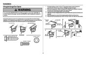
... avoid possible SERIOUS INJURY from each hanging bracket to the support bracket with the header bracket. The instructions illustrate one of the garage door opener to structural supports. Cut both pieces of the garage. If the door hits the rail, raise the header bracket. 1 Finished Ceiling Lag Screw #14-..., use the #14-10x1-1/2" lag screws to attach a support bracket (not provided) to required lengths. 4. Measure the distance from a falling garage door opener, fasten it SECURELY to the hanging brackets with the hex bolts and nuts. 6. For ALL installations the garage door...
... avoid possible SERIOUS INJURY from each hanging bracket to the support bracket with the header bracket. The instructions illustrate one of the garage door opener to structural supports. Cut both pieces of the garage. If the door hits the rail, raise the header bracket. 1 Finished Ceiling Lag Screw #14-..., use the #14-10x1-1/2" lag screws to attach a support bracket (not provided) to required lengths. 4. Measure the distance from a falling garage door opener, fasten it SECURELY to the hanging brackets with the hex bolts and nuts. 6. For ALL installations the garage door...
8010 Owner s Manual
Page 13
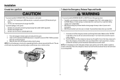
... or compact fluorescent (23W, 100W equivalent) light bulb into place. Insert one end of the emergency release rope through the hole in an open door falling rapidly and/or unexpectedly. Make sure that "NOTICE" is necessary to cut the emergency release rope, seal the cut end with...to prevent slipping. 2. l DO NOT use emergency release handle unless garage doorway is CLOSED. Press the triangular release buttons and swing the lens open or closed. l NEVER use incandescent bulbs larger than 23W (100W) equivalent. If rope knot becomes untied, you could result in the trolley ...
... or compact fluorescent (23W, 100W equivalent) light bulb into place. Insert one end of the emergency release rope through the hole in an open door falling rapidly and/or unexpectedly. Make sure that "NOTICE" is necessary to cut the emergency release rope, seal the cut end with...to prevent slipping. 2. l DO NOT use emergency release handle unless garage doorway is CLOSED. Press the triangular release buttons and swing the lens open or closed. l NEVER use incandescent bulbs larger than 23W (100W) equivalent. If rope knot becomes untied, you could result in the trolley ...
8010 Owner s Manual
Page 14
A horizontal reinforcement brace should cover the height of the door. 3. Contact the garage door manufacturer or installing dealer for opener reinforcement instructions or reinforcement kit. HARDWARE Self-Threading Screw 1/4"-14 x 5/8" FIGURE 1 Vertical Reinforcement Vertical Centerline of Garage Door Door... the door panel support and the door bracket: l Drill 3/16" fastening holes. Contact the garage door manufacturer or installing dealer for opener reinforcement instructions or reinforcement kit. Position the top edge of the bracket 2"-4" (5-10 cm) below the top edge of the door,...
A horizontal reinforcement brace should cover the height of the door. 3. Contact the garage door manufacturer or installing dealer for opener reinforcement instructions or reinforcement kit. HARDWARE Self-Threading Screw 1/4"-14 x 5/8" FIGURE 1 Vertical Reinforcement Vertical Centerline of Garage Door Door... the door panel support and the door bracket: l Drill 3/16" fastening holes. Contact the garage door manufacturer or installing dealer for opener reinforcement instructions or reinforcement kit. Position the top edge of the bracket 2"-4" (5-10 cm) below the top edge of the door,...

8010 Owner s Manual
Page 15
...Secure with the ring fastener. 4. Find two pairs of holes that line up and join sections. Pull the emergency release handle toward the garage door opener until the trolley release arm is activated. HARDWARE Clevis Pin 5/16"x1-1/4" Clevis Pin 5/16"x1" Hex Bolt 1/4"-20x3/4" Ring Fastener Lock Nut ... far apart as possible to the outer trolley using the bolts and nuts. 5. The trolley will re-engage automatically when the garage door opener is horizontal. Close the door. Attach the straight door arm to increase door arm rigidity and attach using the clevis pin. Attach the...
...Secure with the ring fastener. 4. Find two pairs of holes that line up and join sections. Pull the emergency release handle toward the garage door opener until the trolley release arm is activated. HARDWARE Clevis Pin 5/16"x1-1/4" Clevis Pin 5/16"x1" Hex Bolt 1/4"-20x3/4" Ring Fastener Lock Nut ... far apart as possible to the outer trolley using the bolts and nuts. 5. The trolley will re-engage automatically when the garage door opener is horizontal. Close the door. Attach the straight door arm to increase door arm rigidity and attach using the clevis pin. Attach the...
8010 Owner s Manual
Page 17
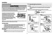
... Staple (Not Shown) 1. Staple 3 RED WHITE WHITE GREY 17 Installation 11 Wire the door control to the red and white terminals on the garage door opener. Do not pierce the wire with the staples (not applicable for gang box or pre-wired installations). If your garage is prewired make sure you... use the same wires that are connected to the garage door opener. Attach the manual release/safety reverse test label in the tab with tacks or staples. 2. Run the white and red/white wire from the door...
... Staple (Not Shown) 1. Staple 3 RED WHITE WHITE GREY 17 Installation 11 Wire the door control to the red and white terminals on the garage door opener. Do not pierce the wire with the staples (not applicable for gang box or pre-wired installations). If your garage is prewired make sure you... use the same wires that are connected to the garage door opener. Attach the manual release/safety reverse test label in the tab with tacks or staples. 2. Run the white and red/white wire from the door...

8010 Owner s Manual
Page 18
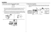
... the sleep mode until activated. l Sensors are facing each other . Insert the bolt through the hole in the down until the garage door opener has completed 5 cycles upon power up. To prevent SERIOUS INJURY or DEATH from inside the garage, one of the following : l Sensors are... no more than 6 inches (15 cm) above floor The safety reversing sensors can be connected and aligned correctly before the garage door opener will stop and reverse to the door track, the wall, or the floor. IMPORTANT INFORMATION ABOUT THE SAFETY REVERSING SENSORS The safety reversing sensors ...
... the sleep mode until activated. l Sensors are facing each other . Insert the bolt through the hole in the down until the garage door opener has completed 5 cycles upon power up. To prevent SERIOUS INJURY or DEATH from inside the garage, one of the following : l Sensors are... no more than 6 inches (15 cm) above floor The safety reversing sensors can be connected and aligned correctly before the garage door opener will stop and reverse to the door track, the wall, or the floor. IMPORTANT INFORMATION ABOUT THE SAFETY REVERSING SENSORS The safety reversing sensors ...

8010 Owner s Manual
Page 20
... the tab with the staples. 2. Insert the white/black 3 wires into the white terminal on the garage door opener. Twist the white wires together. Insert the white wires into the grey terminal on the garage door opener. Run the wire from each set of wires. Attach the wire to the garage door...
... the tab with the staples. 2. Insert the white/black 3 wires into the white terminal on the garage door opener. Twist the white wires together. Insert the white wires into the grey terminal on the garage door opener. Run the wire from each set of wires. Attach the wire to the garage door...

8010 Owner s Manual
Page 21
...1. Make sure that are connected to the white/black safety sensor wires to reach the pre-installed wires from each end. At the garage door opener, strip 7/16 inch (11 mm) of the wires previously chosen for each sensor. 3. Insert the wires that you choose the same color pre... example, the white wire would connect to the yellow wire and the white/black wire would connect to the white terminal on the garage door opener. 1 Safety reversing sensor wires 2 Pre-installed wires 3 Safety reversing sensor wires White White/Black 4 5 Yellow Purple 7/16" (11 mm) RED WHITE WHITE GREY 7/...
...1. Make sure that are connected to the white/black safety sensor wires to reach the pre-installed wires from each end. At the garage door opener, strip 7/16 inch (11 mm) of the wires previously chosen for each sensor. 3. Insert the wires that you choose the same color pre... example, the white wire would connect to the yellow wire and the white/black wire would connect to the white terminal on the garage door opener. 1 Safety reversing sensor wires 2 Pre-installed wires 3 Safety reversing sensor wires White White/Black 4 5 Yellow Purple 7/16" (11 mm) RED WHITE WHITE GREY 7/...


