GT- Logic 4 Installation Manual
Page 1
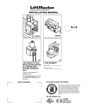
... The Maintenance Alert System™ allows the installer to locate a professional installing dealer in C2 operating mode. Operators are shipped in your area. Visit www.liftmaster.com to set number of cycles/months is reached or when the operator requires immediate service. An LED on Board NOT FOR RESIDENTIAL USE 315MHz Radio Receiver Built...
... The Maintenance Alert System™ allows the installer to locate a professional installing dealer in C2 operating mode. Operators are shipped in your area. Visit www.liftmaster.com to set number of cycles/months is reached or when the operator requires immediate service. An LED on Board NOT FOR RESIDENTIAL USE 315MHz Radio Receiver Built...
GT- Logic 4 Installation Manual
Page 2
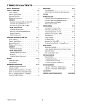
... (LMEP 20 Install the Photoelectric Sensors (Provided 21 Mount the Photoelectric Sensors (Provided 22 Wire the LiftMaster Monitored Entrapment Protection (LMEP) Devices 22 ADJUSTMENT 23-24 Limit Adjustment 23 Clutch Adjustment (Belt Drive Model Operators 24 TESTING 25 MANUAL RELEASE 26-27 Emergency Disconnect System Model GT and T 26 Emergency Disconnect System...
... (LMEP 20 Install the Photoelectric Sensors (Provided 21 Mount the Photoelectric Sensors (Provided 22 Wire the LiftMaster Monitored Entrapment Protection (LMEP) Devices 22 ADJUSTMENT 23-24 Limit Adjustment 23 Clutch Adjustment (Belt Drive Model Operators 24 TESTING 25 MANUAL RELEASE 26-27 Emergency Disconnect System Model GT and T 26 Emergency Disconnect System...

GT- Logic 4 Installation Manual
Page 3
...your commercial door and WARNING gate operator unless you are an Authorized Service Technician. • Operator intended to be made by a trained door systems technician BEFORE installing operator. 4. AVERTISSEMENT AAAVVETEITRMRETPTNIOSISTRSISOTEEANMMNETENNITNTSTALLATION INSTRUCTIAOANVVSEERRTTIISSSSEEMMEENNTT WARNING ...WARNING Mechanical CWAWAUARTRINONINNINGG Electrical CWAUATRIONINNG WARNING IMPORTANT NOTES: • BEFORE attempting to install, operate or maintain the operator, you must read and fully understand this Signal Word on the following pages, they ...
...your commercial door and WARNING gate operator unless you are an Authorized Service Technician. • Operator intended to be made by a trained door systems technician BEFORE installing operator. 4. AVERTISSEMENT AAAVVETEITRMRETPTNIOSISTRSISOTEEANMMNETENNITNTSTALLATION INSTRUCTIAOANVVSEERRTTIISSSSEEMMEENNTT WARNING ...WARNING Mechanical CWAWAUARTRINONINNINGG Electrical CWAUATRIONINNG WARNING IMPORTANT NOTES: • BEFORE attempting to install, operate or maintain the operator, you must read and fully understand this Signal Word on the following pages, they ...
GT- Logic 4 Installation Manual
Page 4
... pressure to CLOSE, plus wiring for 3/4 HP and higher (all components were provided. SAFETY DISCONNECT Quick disconnect door arm for optional wiring types and operating modes. ENTRAPMENT PROTECTION: LiftMaster Monitored Entrapment Protection (LMEP) Photoelectric Sensors (CPS-U Through beam used to open and close with LED Trolley drive chain: #48 for 1/3 and 1/2 HP...
... pressure to CLOSE, plus wiring for 3/4 HP and higher (all components were provided. SAFETY DISCONNECT Quick disconnect door arm for optional wiring types and operating modes. ENTRAPMENT PROTECTION: LiftMaster Monitored Entrapment Protection (LMEP) Photoelectric Sensors (CPS-U Through beam used to open and close with LED Trolley drive chain: #48 for 1/3 and 1/2 HP...
GT- Logic 4 Installation Manual
Page 5
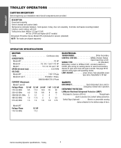
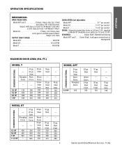
Steel Wood Doors 24 ga. Steel Insul. 175 250 325 400 --- --- 16 ga. Steel Alum. Steel Insul. 200 250 300 380 5 Operator specifications/Maximum door area - Steel Insul. 260 320 450 560 16 ga. Steel Insul. 225 16 ga. Steel Wood Doors 24 ga. Output: #... --- --- 16 ga. Fiberglass Doors 24 ga. 22 ga. Steel Alum. Steel Insul. 125 200 275 310 STANDARD SECTIONAL MODEL APT 24 ga. 22 ga. TROLLEY OPERATOR SPECIFICATIONS MECHANICAL DRIVE REDUCTION: Model APT and T Primary: Heavy duty (5L) V-Belt Secondary: #41 chain/sprocket;
Steel Wood Doors 24 ga. Steel Insul. 175 250 325 400 --- --- 16 ga. Steel Alum. Steel Insul. 200 250 300 380 5 Operator specifications/Maximum door area - Steel Insul. 260 320 450 560 16 ga. Steel Insul. 225 16 ga. Steel Wood Doors 24 ga. Output: #... --- --- 16 ga. Fiberglass Doors 24 ga. 22 ga. Steel Alum. Steel Insul. 125 200 275 310 STANDARD SECTIONAL MODEL APT 24 ga. 22 ga. TROLLEY OPERATOR SPECIFICATIONS MECHANICAL DRIVE REDUCTION: Model APT and T Primary: Heavy duty (5L) V-Belt Secondary: #41 chain/sprocket;
GT- Logic 4 Installation Manual
Page 7
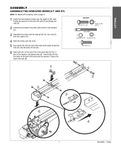
Trolley TROLLEY ASSEMBLY ASSEMBLE THE OPERATOR (MODELS T AND GT) NOTE: For Model APT assembly refer to the track with bolts (F) and washers (D). 3 Assemble the trolley with nuts (B). 1 HARDWARE A Bolt 3/8"-16 x 3/4" B Flange ... bolt (A) and flange hex nuts (B). 2 Install the front idler to page 9. 1 Install the track spacers evenly over the length of the track and the operator. Insert bolts (A) into the "L" slot in the...
Trolley TROLLEY ASSEMBLY ASSEMBLE THE OPERATOR (MODELS T AND GT) NOTE: For Model APT assembly refer to the track with bolts (F) and washers (D). 3 Assemble the trolley with nuts (B). 1 HARDWARE A Bolt 3/8"-16 x 3/4" B Flange ... bolt (A) and flange hex nuts (B). 2 Install the front idler to page 9. 1 Install the track spacers evenly over the length of the track and the operator. Insert bolts (A) into the "L" slot in the...
GT- Logic 4 Installation Manual
Page 8
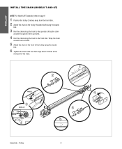
... sprocket. 4 Run the chain along the track to the operator. Wrap the chain around the front idler. 5 Attach the chain to the front of the track. 2 1 2˝ MODEL T 3 MODEL GT 4 5 6 3˝ Assembly - Trolley 8 TROLLEY INSTALL ...
... sprocket. 4 Run the chain along the track to the operator. Wrap the chain around the front idler. 5 Attach the chain to the front of the track. 2 1 2˝ MODEL T 3 MODEL GT 4 5 6 3˝ Assembly - Trolley 8 TROLLEY INSTALL ...
GT- Logic 4 Installation Manual
Page 9
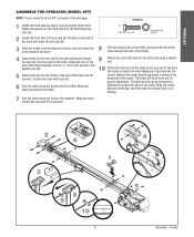
...into the "L" slot in the second set of holes on the end of the track). TROLLEY ASSEMBLE THE OPERATOR (MODEL APT) NOTE: If your model is no binding. 7 Run the chain along the track to the...the spacers to the track with bolt (A) and flange hex nuts (B). 2 Install the front idler in the operator and tighten nuts (B). 5 Insert bolts (A) into the end of the track and loosely thread the nuts (B) onto the... ends of the track with nuts (B). 6 Run the chain along the track to the operator. Slide the trolley back and forth past the drive chain to ensure there is not an APT, ...
...into the "L" slot in the second set of holes on the end of the track). TROLLEY ASSEMBLE THE OPERATOR (MODEL APT) NOTE: If your model is no binding. 7 Run the chain along the track to the...the spacers to the track with bolt (A) and flange hex nuts (B). 2 Install the front idler in the operator and tighten nuts (B). 5 Insert bolts (A) into the end of the track and loosely thread the nuts (B) onto the... ends of the track with nuts (B). 6 Run the chain along the track to the operator. Slide the trolley back and forth past the drive chain to ensure there is not an APT, ...

GT- Logic 4 Installation Manual
Page 10
... out of travel mark 4 inches above the highest point of balance. Typically, the operator may be RIGIDLY fastened to 24 inches off center mounting may be used if mounting header bracket or 2x4 into masonry. • NEVER try to ...
... out of travel mark 4 inches above the highest point of balance. Typically, the operator may be RIGIDLY fastened to 24 inches off center mounting may be used if mounting header bracket or 2x4 into masonry. • NEVER try to ...

GT- Logic 4 Installation Manual
Page 11
... the track and header bracket holes. CAUTION To avoid possible SERIOUS INJURY from a falling operator: • Fasten the operator SECURELY to structural supports of the operator. Trolley HARDWARE Header Pivot Pin (1) Cotter pins (2) 1 2 3 WARNING HANG THE OPERATOR 1 Secure the operator using the appropriate fasteners and locking hardware that will support the weight of the building...
... the track and header bracket holes. CAUTION To avoid possible SERIOUS INJURY from a falling operator: • Fasten the operator SECURELY to structural supports of the operator. Trolley HARDWARE Header Pivot Pin (1) Cotter pins (2) 1 2 3 WARNING HANG THE OPERATOR 1 Secure the operator using the appropriate fasteners and locking hardware that will support the weight of the building...

GT- Logic 4 Installation Manual
Page 12
... door arm to door manufacturer's instructions for recommended installation guidelines. NOTE: When properly installed and adjusted the door arm should be leaning back toward the operator slightly. Trolley 12 HARDWARE A Flanged Hex Nut 3/8"-16 (2) B Nylok Nut 3/8"-16 (1) Bolt 3/8"-16 x 1" (3) NOTICE 1 A B 2 Typical installation - Refer to the trolley. Make sure the open side...
... door arm to door manufacturer's instructions for recommended installation guidelines. NOTE: When properly installed and adjusted the door arm should be leaning back toward the operator slightly. Trolley 12 HARDWARE A Flanged Hex Nut 3/8"-16 (2) B Nylok Nut 3/8"-16 (1) Bolt 3/8"-16 x 1" (3) NOTICE 1 A B 2 Typical installation - Refer to the trolley. Make sure the open side...
GT- Logic 4 Installation Manual
Page 13
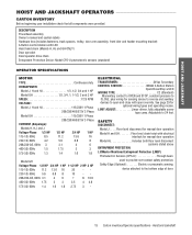
...idler and header mounting bracket) 3-Button control station with electrical interlock for manual door operation Model HJ Includes both floor level disconnect systems stated above ENTRAPMENT PROTECTION: LiftMaster Monitored Entrapment Protection (LMEP) Photoelectric Sensors (CPS-U Through beam used to CLOSE, ...plus wiring for optional wiring types and operating modes. See page 29 for sensing device to reverse ...
...idler and header mounting bracket) 3-Button control station with electrical interlock for manual door operation Model HJ Includes both floor level disconnect systems stated above ENTRAPMENT PROTECTION: LiftMaster Monitored Entrapment Protection (LMEP) Photoelectric Sensors (CPS-U Through beam used to CLOSE, ...plus wiring for optional wiring types and operating modes. See page 29 for sensing device to reverse ...
GT- Logic 4 Installation Manual
Page 14
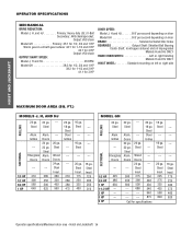
...285 1/2 HP 400 350 3/4 HP 560 500 1 HP 640 625 --- --- 20 ga. Grilles --- Steel Insul. 175 225 300 375 460 620 Operator specifications/Maximum door area - Doors 24 ga. 22 ga. Steel Insul. 125 200 250 310 MODEL GH 24 ga. Doors 24 ga. ... HP --- 3 HP --- 5 HP 22 ga. FT.) MODELS J, H, AND HJ 24 ga. 22 ga. Steel --- --- --- 16 ga. --Steel --- --- 20 ga. Steel Alum. OPERATOR SPECIFICATIONS MECHANICAL DRIVE REDUCTION: Model J, H, and HJ Primary: Heavy duty (5L) V-Belt Secondary: #48 chain/sprocket; Steel ROLLING Alum. Steel Wood Doors 24 ga. Steel...
...285 1/2 HP 400 350 3/4 HP 560 500 1 HP 640 625 --- --- 20 ga. Grilles --- Steel Insul. 175 225 300 375 460 620 Operator specifications/Maximum door area - Doors 24 ga. 22 ga. Steel Insul. 125 200 250 310 MODEL GH 24 ga. Doors 24 ga. ... HP --- 3 HP --- 5 HP 22 ga. FT.) MODELS J, H, AND HJ 24 ga. 22 ga. Steel --- --- --- 16 ga. --Steel --- --- 20 ga. Steel Alum. OPERATOR SPECIFICATIONS MECHANICAL DRIVE REDUCTION: Model J, H, and HJ Primary: Heavy duty (5L) V-Belt Secondary: #48 chain/sprocket; Steel ROLLING Alum. Steel Wood Doors 24 ga. Steel...
GT- Logic 4 Installation Manual
Page 15
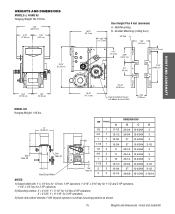
...59.51 cm) Hand Chain Wheel Present with 1" x 1/4" key for 1/2 thru 1 HP operators, 1-3/16" x 5/16" key for 1-1/2 and 2 HP operators, 1-1/4" x 1/4" key for 3 HP operators. 2) Mounting centers: X = 4-3/4"; Y = 9-1/16" for 1/2 thru 2 HP operators. WEIGHTS AND DIMENSIONS HANGING WEIGHT: .........80-110 LBS. 14" (35.1546 "cm) A...11.58 cm) HOIST AND JACKSHAFT MODEL GH Hanging Weight: 140 lbs. Y = 5-1/2" for 3 HP operators. 3) Hand chain wheel extends 1-5/8" beyond operator in vertical mounting position as shown. 15 Weights and dimensions - X = 3-5/8"; Hoist and Jackshaft WEIGHTS AND ...
...59.51 cm) Hand Chain Wheel Present with 1" x 1/4" key for 1/2 thru 1 HP operators, 1-3/16" x 5/16" key for 1-1/2 and 2 HP operators, 1-1/4" x 1/4" key for 3 HP operators. 2) Mounting centers: X = 4-3/4"; Y = 9-1/16" for 1/2 thru 2 HP operators. WEIGHTS AND DIMENSIONS HANGING WEIGHT: .........80-110 LBS. 14" (35.1546 "cm) A...11.58 cm) HOIST AND JACKSHAFT MODEL GH Hanging Weight: 140 lbs. Y = 5-1/2" for 3 HP operators. 3) Hand chain wheel extends 1-5/8" beyond operator in vertical mounting position as shown. 15 Weights and dimensions - X = 3-5/8"; Hoist and Jackshaft WEIGHTS AND ...
GT- Logic 4 Installation Manual
Page 16
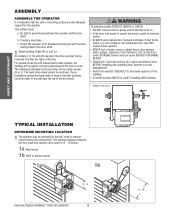
... EXTREME tension and can be used if installing ANY brackets. EXAMPLE: Right Hand HOIST AND JACKSHAFT TYPICAL INSTALLATION DEATDERVMEINRETMEOUNNCTIIANG LOCATION 1 The operator may NOT reverse when required. • NEVER try to remain functional, install an interlock switch. • ALWAYS call a trained.... • Concrete anchors MUST be mounted on the wall, shelf or bracket (not provided, see accessories). ASSWEMARBLNYING WARNING CAUTION ASSEMBLE THE OPERATOR It is 12 - 15 inches. 1a Wall mount 1b Shelf or bracket mount 1a 1b ADVERTENCIA ADVERTENCIA 12" - 15" Assembly/Typical...
... EXTREME tension and can be used if installing ANY brackets. EXAMPLE: Right Hand HOIST AND JACKSHAFT TYPICAL INSTALLATION DEATDERVMEINRETMEOUNNCTIIANG LOCATION 1 The operator may NOT reverse when required. • NEVER try to remain functional, install an interlock switch. • ALWAYS call a trained.... • Concrete anchors MUST be mounted on the wall, shelf or bracket (not provided, see accessories). ASSWEMARBLNYING WARNING CAUTION ASSEMBLE THE OPERATOR It is 12 - 15 inches. 1a Wall mount 1b Shelf or bracket mount 1a 1b ADVERTENCIA ADVERTENCIA 12" - 15" Assembly/Typical...

GT- Logic 4 Installation Manual
Page 17
.... 4 Align the door and the drive sprockets. Hoist and Jackshaft MOUNTING 1 Place the door sprocket on the door shaft. 2 Place the operator drive sprocket on the appropriate side of the operator for your installation type. 3 Wrap the drive chain around the door sprocket and the drive sprocket then secure with the set...
.... 4 Align the door and the drive sprockets. Hoist and Jackshaft MOUNTING 1 Place the door sprocket on the door shaft. 2 Place the operator drive sprocket on the appropriate side of the operator for your installation type. 3 Wrap the drive chain around the door sprocket and the drive sprocket then secure with the set...

GT- Logic 4 Installation Manual
Page 18
...rotation of the motor and logic board may be on the logic board. Relocate the safety limit switch (SLS) to the opposite side. 3. Operator MUST be properly grounded. POWER WIRING CHART DISTANCE GAUGE 50 feet 14 AWG 100 feet 12 AWG 200 feet 8 AWG* 350 feet 6 ... Phase 1 Phase 2 Phase 3 WIRING Wiring - WIRING WARNING To reduce the risk of SEVERE INJURY or DEATH: • ANY maintenance to the operator or in accordance with national and local electrical codes. NOTE: In some installations, such as indicated on a separate fused line of adequate capacity. •...
...rotation of the motor and logic board may be on the logic board. Relocate the safety limit switch (SLS) to the opposite side. 3. Operator MUST be properly grounded. POWER WIRING CHART DISTANCE GAUGE 50 feet 14 AWG 100 feet 12 AWG 200 feet 8 AWG* 350 feet 6 ... Phase 1 Phase 2 Phase 3 WIRING Wiring - WIRING WARNING To reduce the risk of SEVERE INJURY or DEATH: • ANY maintenance to the operator or in accordance with national and local electrical codes. NOTE: In some installations, such as indicated on a separate fused line of adequate capacity. •...

GT- Logic 4 Installation Manual
Page 19
...Clear! Control station Door May Move at any Time Without Prior Warning Do Not Let Children Operate the Door or Play in the Door Area Keep Door in contact with the door while operating the controls. The installation surface must be smooth and flat all Times When Door...door control. NING CONTROL STATION WARNING ON WARNING To prevent possible SERIOUS INJURY or DEATH from the door. • NEVER permit children to the operator. To prevent possible SERIOUS INJURY or DEATH from a closing door. • Install the control station far enough from ALL moving parts of children...
...Clear! Control station Door May Move at any Time Without Prior Warning Do Not Let Children Operate the Door or Play in the Door Area Keep Door in contact with the door while operating the controls. The installation surface must be smooth and flat all Times When Door...door control. NING CONTROL STATION WARNING ON WARNING To prevent possible SERIOUS INJURY or DEATH from the door. • NEVER permit children to the operator. To prevent possible SERIOUS INJURY or DEATH from a closing door. • Install the control station far enough from ALL moving parts of children...
GT- Logic 4 Installation Manual
Page 20
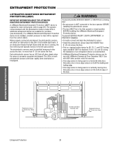
...sensor beam NO HIGHER than 6" (15 cm) above floor ENTRAPMENT PROTECTION Entrapment Protection 20 The operator comes standard with LiftMaster Commercial Door Operators ONLY. Each photoelectric sensor has an LED that will glow steady when the sensor is a .... Right Side of the door. ENTWRAAPRMNEINNGT PROTECTION WARNING LPIRFOTTCMEAACSTUTIEOTRNIOM(LONMNEIPT)ORED ENTRAPMENT IMPORTANT INFORMATION ABOUT THE LIFTMASTER MONITORED ENTRAPMENT PROTECTION DEVICES A LiftMaster Monitored Entrapment Protection (LMEP) device is not installed, constant pressure to close will be required from...
...sensor beam NO HIGHER than 6" (15 cm) above floor ENTRAPMENT PROTECTION Entrapment Protection 20 The operator comes standard with LiftMaster Commercial Door Operators ONLY. Each photoelectric sensor has an LED that will glow steady when the sensor is a .... Right Side of the door. ENTWRAAPRMNEINNGT PROTECTION WARNING LPIRFOTTCMEAACSTUTIEOTRNIOM(LONMNEIPT)ORED ENTRAPMENT IMPORTANT INFORMATION ABOUT THE LIFTMASTER MONITORED ENTRAPMENT PROTECTION DEVICES A LiftMaster Monitored Entrapment Protection (LMEP) device is not installed, constant pressure to close will be required from...
GT- Logic 4 Installation Manual
Page 22
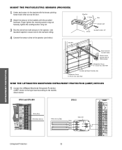
above floor WIRE THE LIFTMASTER MONITORED ENTRAPMENT PROTECTION (LMEP) DEVICES 1 Connect the LiftMaster Monitored Entrapment Protection (LMEP) device to the logic board according to the models shown below ). Bell Wire Wing Nut "C" Wrap Wire Indicator Light Sensor... LMEP2 E2 LMEP1 E3 E4 40-34141-1 Entrapment Protection 22 Securely tighten the sending sensor wing nut. 3 Run the wires from both sensors to the operator. MOUNT THE PHOTOELECTRIC SENSORS (PROVIDED) 1 Center each sensor in the bracket with the lenses pointing toward each other across the door. 2 Attach the sensors...
above floor WIRE THE LIFTMASTER MONITORED ENTRAPMENT PROTECTION (LMEP) DEVICES 1 Connect the LiftMaster Monitored Entrapment Protection (LMEP) device to the logic board according to the models shown below ). Bell Wire Wing Nut "C" Wrap Wire Indicator Light Sensor... LMEP2 E2 LMEP1 E3 E4 40-34141-1 Entrapment Protection 22 Securely tighten the sending sensor wing nut. 3 Run the wires from both sensors to the operator. MOUNT THE PHOTOELECTRIC SENSORS (PROVIDED) 1 Center each sensor in the bracket with the lenses pointing toward each other across the door. 2 Attach the sensors...


