LiftMaster Icon 26 Support and Manuals
Get Help and Manuals for this LiftMaster item
View All Support Options Below
Free LiftMaster Icon 26 manuals!
Problems with LiftMaster Icon 26?
Ask a Question
Free LiftMaster Icon 26 manuals!
Problems with LiftMaster Icon 26?
Ask a Question
Most Recent LiftMaster Icon 26 Questions

Password
I have the Elite Pro Icon 26 system and I'm trying to load the software on a new computer but can't ...
I have the Elite Pro Icon 26 system and I'm trying to load the software on a new computer but can't ...
(Posted by jwatson49797 12 years ago)
Popular LiftMaster Icon 26 Manual Pages
ICON26 Manual - Page 2

... Password 29 Clock/Timer 30-32 Strike Time 33 Talk Time 33 Greeting 34 Volume Adjustment 34 Back-Up Memory 35 Error Messages 36 Display Controller Board 37 Large Display Battery Back-Up 38 Auxiliary Input/Output 39 Optional Camera 40 Parts List and Part Illustrations 41 Approvals 42
To be installed by Qualified Dealers ONLY! Icon Page
1
Icon26 manual...
ICON26 Manual - Page 4

...Warranty
Factory to help & guide user. • Programmable volume level via modem using "Elite Pro" windows based software. • FCC part 68 ,15 & Canadian DOC approval.
• ETL approved UL 294, UL 1950
SPECIFICATIONS
• Construction: Front and Back Panel: 16 gauge stainless steel. Power input port - Relay ports -
Temperature: Icon26: -4 F to +135 F Icon26-HT: -4 F to avoid...
ICON26 Manual - Page 9

Icon26 FEATURES (INSIDE)
Processor Key Release / Lock
Mounting Holes (4)
Processor Power Switch
Power Backup Unit
Large Display Large Display Power Switch Contrast Adjustment
Microphone
Camera (Optional)
...Suppressor Terminal Board
Postal Lock Setup
External Keypad
Stainless Steel Door
External Speaker
All components and specifications are subject to change without notice. Icon Page
8
ICON26 Manual - Page 12
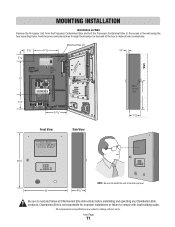
... the Processor Containment Box to make all Chamberlain Elite instructions before installating and operating any Chamberlain Elite products.
Feed the power and phone lines through the knockout in the back of the box to the recess in the wall using the four mounting holes. All components and specifications are subject to comply with local building...
ICON26 Manual - Page 13

... remote security devices.
8 CHASSIS GROUND: Entry Phone MUST be properly grounded. Please refer to the owners manual for proper grounding instructions.
6 VIDEO OUT: Camera video output standard BNC cable connection for use with gate operator to the ground rod.
The provided "chassis ground" wire must be connected to control access through main vehicular gate.
5 DOOR RELAY...
ICON26 Manual - Page 15

... towards the Telephone Entry System. EARTH GROUND ROD INSTALLATION
Proper grounding gives an electrical charge, such as from an electrical static discharge or a near lightning strike, a path from the Telephone Entry System. Although nothing can absorb the tremendous power of wire. If you plan to dissipate its integrity, replace it with all necessary local building codes. Without...
ICON26 Manual - Page 16
...Access Door
Solenoid
OR
OR
Entry...Icon Page
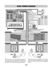
15 Connect two wires to the main vehicular gate operator or door.
NOTE: Installation where fiber optic phone lines are present
Polarity does not matter
may require additional modifications from your provider for Easy Wiring. The door relay will be a dedicated line for the
Telephone Entry...GROUND
CAMERA
TIP
RING
Transformer
Telephone Line...
ICON26 Manual - Page 18

...If unit is not grounded, lightning damage
Installation: 1 Open the front panel of the Telephone Entry System and remove the hole plug.
2 (Retain nuts and washers) Install the postal lock with Postal Lock on...NO COM NC NO
GATE DOOR RELAY RELAY
VIDEO OUT
CHASSIS GROUND
CAMERA
It is MANDATORY that polarity or color coding is activated for a duration according to the programmed "Gate Strike Time...
ICON26 Manual - Page 19

...unique "Device ID Number" set by using the rotary switches on the device. (Refer to specific RS485 Instruction sheets).
Turn Terminator Switch ... the Telephone Entry System is 4000 Ft. • Turn "ON" the terminator switch ONLY for the last device installed in...supported • Maximum distance from the last RS485 device (per wire run) to the Telephone Entry Syetem is 4000 Ft. Icon Page
18
ICON26 Manual - Page 20

... Receiver RS485 Remote Device 2
Card Reader RS485 Remote
Device 3
Icon Page
19
Universal Interface Board RS485 Remote Last Device RS485 DAISY CHAIN ...
Remote Access RS485
COMMUNICATOR CARD
capacity
Main M
ard Slot
RS485 Memory Card Slot
RS485 Card Release Button
NOTE: To support RS485...CAMERA
It is MANDATORY that this unit is not grounded, lightning damage
f r to the ground rod.
ICON26 Manual - Page 21

...NO 2-NC 2-COM 1-COM GND 2-IN 1-IN
Remote Access RS485
COMMUNICATOR CARD
capacity
Main M
Card Slot
RS485 Memory Card Slot
RS485 Card Release Button
NOTE: To support RS485 devices you must be con cte o the ground ...
IN GN V-C V NO
COM NC NO COM NC NO
GATE DOOR RELAY RELAY
VIDEO OUT
CHASSIS GROUND
CAMERA
It i MANDATOR hat s unit is not gro ded ightning damage
r to the owners
Gnd - +
Gnd...
ICON26 Manual - Page 23

...
A Z
X
SPACE BAR
3
1 4
2 5 8
6 9
7
0
I
HELP
T
U
Y
J
H
G
N
F
B
V
C
O K M
P
L
BSAPACCKE
'
The Telephone Entry System is only water resistant when the Stainless Steel Door is closed and locked. Do not drop the Processor or expose it to impact.
WARNINGS ...the Processor Unit or the open Processor Containment Box to rain, snow, or harsh weather conditions.
Icon Page
22
ICON26 Manual - Page 35

... adjust the
volume to the desired level (fig e.).
Icon Page
34 In the Program Selection Screen (fig a.), Press
the G key.
To continue programming, press the
button to complete the entry. Type the name of the facility and press the key to complete your entry on the Welcome screen.(fig b.)
SELECT PROG MODE: (G)Greeting
(fig a.)
FACILITY...
ICON26 Manual - Page 41

...installation instructions please refer to the Video Out connector on the surge suppression terminal board. OPTIONAL CAMERA
1
Part # ICON26CAMERA
This compact, optional color camera is only 22 mm x 26 mm and is capable of 10-bit DSP, 330 line resolution output. 1 Connect camera to surge suppression terminal board with cable supplied with camera...EXIT VCR
CAMERA
SWITCH INPUT RELAY
1
Icon Page
40
ICON26 Manual - Page 42
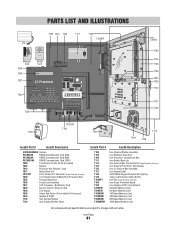
... and specifications are subject to change without notice. No Memory Card
T029
Key for proper grounding instructions
el teen ryph ne com
MADE IN U A
KBRD A AN L GHT RE
AUX 2 RELAY
GATE DOOR RELAY RELAY P
Icon Camera
T180 T104 T106 T148 T003 T029 T140
T137 T132
T000
T012SPT T160
T026
T044
T108
T114
Icon26 Part #
Icon26 Description
ICON26CAMERA Camera...
LiftMaster Icon 26 Reviews
We have not received any reviews for LiftMaster yet.