LM21XP Manual
Page 2
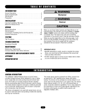
... release device features include a 10-, 20-, 30- Read the warnings carefully. INTRODUCTION GENERAL DESCRIPTION The LiftMaster® LM21XP Release Device is designated to the fire alarm control panel, an audible trouble sounder, and diagnostic feedback ... TABLE OF CONTENTS INTRODUCTION General Description 2 Agency Requirements 3 Specifications 3 WARNING Preparation 3 INSTALLATION Important Installation Warnings 4 CAUTION Mount the Release Device 4 WIRING Wiring Instructions 5 Wiring Diagram 6 Connections of Initiating Devices and Accessories 7-8 Optional Connections 8-9 TESTING ...
... release device features include a 10-, 20-, 30- Read the warnings carefully. INTRODUCTION GENERAL DESCRIPTION The LiftMaster® LM21XP Release Device is designated to the fire alarm control panel, an audible trouble sounder, and diagnostic feedback ... TABLE OF CONTENTS INTRODUCTION General Description 2 Agency Requirements 3 Specifications 3 WARNING Preparation 3 INSTALLATION Important Installation Warnings 4 CAUTION Mount the Release Device 4 WIRING Wiring Instructions 5 Wiring Diagram 6 Connections of Initiating Devices and Accessories 7-8 Optional Connections 8-9 TESTING ...

LM21XP Manual
Page 3
...provided by the appropriate testing and listing agencies in accordance with this device) Refer to NFPA 72 and NFPA 80 for instructions concerning proper placement and detection coverage. Maximum voltage 28Vdc COMMON ALARM AND TROUBLE RELAY: .5A 125Vac, 60Hz (MAX....with specific door being utilized. Max. 9.7" x 7.5" x 5" (h x w x d) WEIGHT: Approximately 8 lbs. Additional items may be required to complete the installation: • Concrete anchors or fasteners • Sash chain or 1/16 cable • Eyebolts-hook • Fuse links • Turnbuckles • Smoke detectors (up...
...provided by the appropriate testing and listing agencies in accordance with this device) Refer to NFPA 72 and NFPA 80 for instructions concerning proper placement and detection coverage. Maximum voltage 28Vdc COMMON ALARM AND TROUBLE RELAY: .5A 125Vac, 60Hz (MAX....with specific door being utilized. Max. 9.7" x 7.5" x 5" (h x w x d) WEIGHT: Approximately 8 lbs. Additional items may be required to complete the installation: • Concrete anchors or fasteners • Sash chain or 1/16 cable • Eyebolts-hook • Fuse links • Turnbuckles • Smoke detectors (up...
LM21XP Manual
Page 4
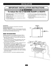
... the National Electric Code. Concrete anchors MUST be performed in accordance with the most current version of end link. Install an eyebolt a minimum distance of the release device enclosure. WARNING I N S TA L L AT I O N IMPORTANT INSTALLATION INSTRUCTIONS WARNING To reduce the risk of enclosure. 2. Mount the release device on releasing device. Remove sash chain or...
... the National Electric Code. Concrete anchors MUST be performed in accordance with the most current version of end link. Install an eyebolt a minimum distance of the release device enclosure. WARNING I N S TA L L AT I O N IMPORTANT INSTALLATION INSTRUCTIONS WARNING To reduce the risk of enclosure. 2. Mount the release device on releasing device. Remove sash chain or...
LM21XP Manual
Page 5
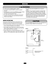
...beginning. 2. Verify that recommended by a qualified individual. • Disconnect power at the fuse box BEFORE proceeding. WIRING INSTRUCTIONS Verify wiring configuration with respect to wiring material type, wiring gauge related to Canadian standards shall be dry contact type. CAUTION...ALL electrical connections MUST be on the side of this product with specific door and accessories being utilized. In addition, ALL installations subject to power capacity requirements and WARNING circuit length and wiring methods. Verify voltage rating of release device to terminal board...
...beginning. 2. Verify that recommended by a qualified individual. • Disconnect power at the fuse box BEFORE proceeding. WIRING INSTRUCTIONS Verify wiring configuration with respect to wiring material type, wiring gauge related to Canadian standards shall be dry contact type. CAUTION...ALL electrical connections MUST be on the side of this product with specific door and accessories being utilized. In addition, ALL installations subject to power capacity requirements and WARNING circuit length and wiring methods. Verify voltage rating of release device to terminal board...
LM21XP Manual
Page 7
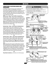
...-installed resistor between terminal positions 5 and 6 remains in Figure 4 or 5, depending upon the type of -line devices must be powered from Terminal Strip 3 NOTE: Follow this device. For proper wiring configurations from multiple smoke detectors or signaling for instructions ...certain that the factoryinstalled jumper between positions 3 and 4 remains in place. This option is a supervised, current-limited circuit. OR Relay Module Installation as an approved UL 1481 regulated power supply providing battery backup support. IN/OUT + OUT + IN - Power from N/O initiating device ...
...-installed resistor between terminal positions 5 and 6 remains in Figure 4 or 5, depending upon the type of -line devices must be powered from Terminal Strip 3 NOTE: Follow this device. For proper wiring configurations from multiple smoke detectors or signaling for instructions ...certain that the factoryinstalled jumper between positions 3 and 4 remains in place. This option is a supervised, current-limited circuit. OR Relay Module Installation as an approved UL 1481 regulated power supply providing battery backup support. IN/OUT + OUT + IN - Power from N/O initiating device ...
LM21XP Manual
Page 10
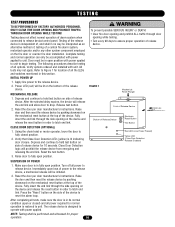
...all power required for 10 seconds. After completing all tests, make sure the door is restored to release device. Verify options ordered and installed with power applied. INITIAL POWER UP 1. WARNING To prevent possible SERIOUS INJURY or DEATH: CAUTION • Clear fire door opening and prohibit.... NOTE: Testing shall be lit on the side of the release device. Refer to drop. Reset the door per door manufacturer's instructions. The release device is lit indicating door closure. CLEAR FIRE DOOR OPENING AND PROHIBIT TRAFFIC THROUGH DOOR OPENING WHILE TESTING! Testing does ...
...all power required for 10 seconds. After completing all tests, make sure the door is restored to release device. Verify options ordered and installed with power applied. INITIAL POWER UP 1. WARNING To prevent possible SERIOUS INJURY or DEATH: CAUTION • Clear fire door opening and prohibit.... NOTE: Testing shall be lit on the side of the release device. Refer to drop. Reset the door per door manufacturer's instructions. The release device is lit indicating door closure. CLEAR FIRE DOOR OPENING AND PROHIBIT TRAFFIC THROUGH DOOR OPENING WHILE TESTING! Testing does ...
LM21XP Manual
Page 11
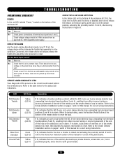
... 5 and 6), resulting from either incorrect wiring or incorrect placement of the end-of this manual for correct wiring instructions. Refer to the Smoke Detector Installation section on pages 7 and 8 of -line resistor, and the smoke detector loop is in alarm. If lit...emanating from terminal board positions 3 and 4), resulting from either incorrect wiring or incorrect placement of this manual for correct wiring instructions. Refer to the Smoke Detector Installation section on pages 7 and 8 of the endof-line relay or the detector(s) are disconnected from terminal board positions 3...
... 5 and 6), resulting from either incorrect wiring or incorrect placement of the end-of this manual for correct wiring instructions. Refer to the Smoke Detector Installation section on pages 7 and 8 of -line resistor, and the smoke detector loop is in alarm. If lit...emanating from terminal board positions 3 and 4), resulting from either incorrect wiring or incorrect placement of this manual for correct wiring instructions. Refer to the Smoke Detector Installation section on pages 7 and 8 of the endof-line relay or the detector(s) are disconnected from terminal board positions 3...


