RSL12U Installation Manual
Page 3
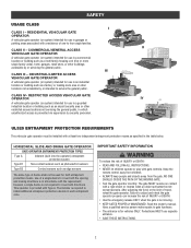
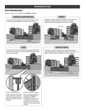
...gate...gate. Have a qualified service person make repairs to cover both directions. INDUSTRIAL/LIMITED ACCESS VEHICULAR GATE OPERATOR A vehicular gate...gate is required to adjust and retest the gate...moving. • KEEP GATES PROPERLY MAINTAINED. Pedestrians MUST...gate MUST reverse on contact with a residence of travel, retest the gate...GATE. • Test the gate operator monthly. CLASS II - HORIZONTAL SLIDE AND SWING GATE OPERATOR GATE... RESIDENTIAL VEHICULAR GATE OPERATOR A vehicular gate operator (or...GATE OPERATOR A vehicular gate operator (or system) intended for...
...gate...gate. Have a qualified service person make repairs to cover both directions. INDUSTRIAL/LIMITED ACCESS VEHICULAR GATE OPERATOR A vehicular gate...gate is required to adjust and retest the gate...moving. • KEEP GATES PROPERLY MAINTAINED. Pedestrians MUST...gate MUST reverse on contact with a residence of travel, retest the gate...GATE. • Test the gate operator monthly. CLASS II - HORIZONTAL SLIDE AND SWING GATE OPERATOR GATE... RESIDENTIAL VEHICULAR GATE OPERATOR A vehicular gate operator (or...GATE OPERATOR A vehicular gate operator (or system) intended for...
RSL12U Installation Manual
Page 4
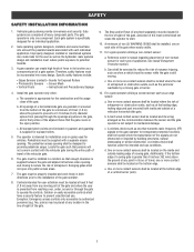
... the risk of a vertical barrier (arm). 3 b. All exposed pinch points are comprised of the gate. The gate must be located in the open into public access areas. 7. Controls intended for exposed rollers. 5. Exception: Emergency access controls only accessible by a...is appropriate for installation only on the bottom edge. The gate must reduce public exposure to reduce the risk of the gate operator. 8. A gate operator can create risks for an individual application. 2. The pedestrian access opening and closing to potential hazards. 3. b. d. b. ...
... the risk of a vertical barrier (arm). 3 b. All exposed pinch points are comprised of the gate. The gate must be located in the open into public access areas. 7. Controls intended for exposed rollers. 5. Exception: Emergency access controls only accessible by a...is appropriate for installation only on the bottom edge. The gate must reduce public exposure to reduce the risk of the gate operator. 8. A gate operator can create risks for an individual application. 2. The pedestrian access opening and closing to potential hazards. 3. b. d. b. ...
RSL12U Installation Manual
Page 5
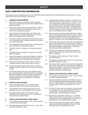
.... 2. These stops shall be installed at either direction along the arc of the moving vehicular access gate. A pedestrian gate shall not be installed at either the fully open and fully closed position, shall not exceed 2 1/4 inches (57 mm), refer to ASTM F2200 for Exception. 3.1.4... 1.9 For pedestrian access in the vicinity of this specification in effect at that the gate covers in the open position shall not exceed 4 inches (102 mm), measured from the supporting hardware. 1.3 Gates shall have smooth bottom edges, with vertical bottom edged protrusions not exceeding 0.50 inches ...
.... 2. These stops shall be installed at either direction along the arc of the moving vehicular access gate. A pedestrian gate shall not be installed at either the fully open and fully closed position, shall not exceed 2 1/4 inches (57 mm), refer to ASTM F2200 for Exception. 3.1.4... 1.9 For pedestrian access in the vicinity of this specification in effect at that the gate covers in the open position shall not exceed 4 inches (102 mm), measured from the supporting hardware. 1.3 Gates shall have smooth bottom edges, with vertical bottom edged protrusions not exceeding 0.50 inches ...
RSL12U Installation Manual
Page 8
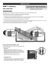
... fit specifications of the gate's path. Gate must be UL approved for vehicles 14 feet (4.27 m) or longer. Because the coasting distance may vary due to changes in temperature, it is NOT recommended to install a stop or catch post in front of operator (refer to stay open when vehicles are recommended. SAFETY CATCH...
... fit specifications of the gate's path. Gate must be UL approved for vehicles 14 feet (4.27 m) or longer. Because the coasting distance may vary due to changes in temperature, it is NOT recommended to install a stop or catch post in front of operator (refer to stay open when vehicles are recommended. SAFETY CATCH...
RSL12U Installation Manual
Page 9
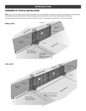
... Sensor Edge Sensor Photoelectric Sensors Operator DUAL GATE Earth Ground Rod Check national and local codes for proper depth Water Tight Conduit (Not provided) NOTE: Power and control wiring MUST be exercised to reduce the risk of entrapment or obstruction exists at either the opening or closing direction. INTRODUCTION OVERVIEW OF TYPICAL...
... Sensor Edge Sensor Photoelectric Sensors Operator DUAL GATE Earth Ground Rod Check national and local codes for proper depth Water Tight Conduit (Not provided) NOTE: Power and control wiring MUST be exercised to reduce the risk of entrapment or obstruction exists at either the opening or closing direction. INTRODUCTION OVERVIEW OF TYPICAL...
RSL12U Installation Manual
Page 11
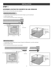
... a concrete pad (reinforced concrete is recommended). 1/2" (1.8 cm) (conduit location) (Gate in the OPEN position. The gate operator should be installed near the back of the gate in open position) 1"-2" (2.5-5.1 cm) Back of the gate. Pour a concrete pad (reinforced concrete is recommended). 1" - 2" (2.5 - 5.1 cm) 1/2" (1.8 cm) (conduit location) (Gate) Front gate roller 24" (61 cm) 24" (61 cm) (Pad) (conduit) REAR...
... a concrete pad (reinforced concrete is recommended). 1/2" (1.8 cm) (conduit location) (Gate in the OPEN position. The gate operator should be installed near the back of the gate in open position) 1"-2" (2.5-5.1 cm) Back of the gate. Pour a concrete pad (reinforced concrete is recommended). 1" - 2" (2.5 - 5.1 cm) 1/2" (1.8 cm) (conduit location) (Gate) Front gate roller 24" (61 cm) 24" (61 cm) (Pad) (conduit) REAR...

RSL12U Installation Manual
Page 12
INSTALLATION STEP 2 INSTALL THE OPERATOR Attach the operator to the concrete pad with appropriate fasteners. The space between the gate and the output sprocket must be installed near the front roller of the gate or near the back of 4 inches. 4 Concrete Anchors 1/2" x 3 1/2" MOUNTING FOOTPRINT .63" 7.49" 13.65" 4" (10 cm) (chain location) (operator) 11 The gate operator should be a minimum of the gate (in the OPEN position).
INSTALLATION STEP 2 INSTALL THE OPERATOR Attach the operator to the concrete pad with appropriate fasteners. The space between the gate and the output sprocket must be installed near the front roller of the gate or near the back of 4 inches. 4 Concrete Anchors 1/2" x 3 1/2" MOUNTING FOOTPRINT .63" 7.49" 13.65" 4" (10 cm) (chain location) (operator) 11 The gate operator should be a minimum of the gate (in the OPEN position).
RSL12U Installation Manual
Page 13
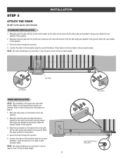
... chain will be level with the top idler pulley and parallel to the ground. Weld the front bracket in this position. 2. Manually close the gate and line up the front bracket so the chain will require two extra idler pulleys. Weld the upper bracket in this position. 4. Manually close...than 1 inch of sag for every 10 feet of chain length. 12 Front Bracket Idler Pulley MUST have excessive slack. STANDARD INSTALLATION 1. Manually open the gate and line up the rear bracket so the chain will be level with the bottom idler pulley and parallel to the ground. Chain should have...
... chain will be level with the top idler pulley and parallel to the ground. Weld the front bracket in this position. 2. Manually close the gate and line up the front bracket so the chain will require two extra idler pulleys. Weld the upper bracket in this position. 4. Manually close...than 1 inch of sag for every 10 feet of chain length. 12 Front Bracket Idler Pulley MUST have excessive slack. STANDARD INSTALLATION 1. Manually open the gate and line up the rear bracket so the chain will be level with the bottom idler pulley and parallel to the ground. Chain should have...

RSL12U Installation Manual
Page 14
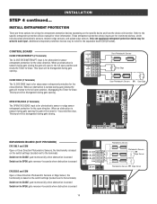
... Sensor for EACH entrapment zone prior to protect between a moving , the gate will stop . The gate will not be able to travel in BOTH the open and close gate cycles. • Locate entrapment protection devices to gate movement. NON-CONTACT SENSORS If the photoelectric sensor beam gets blocked while the... it will not run. Monitored photoelectric sensors MUST be installed to travel in that direction will stop and reverse. The gate will stop and reverse. Use only LiftMaster approved entrapment protection devices (refer to test entrapment protection devices monthly.
... Sensor for EACH entrapment zone prior to protect between a moving , the gate will stop . The gate will not be able to travel in BOTH the open and close gate cycles. • Locate entrapment protection devices to gate movement. NON-CONTACT SENSORS If the photoelectric sensor beam gets blocked while the... it will not run. Monitored photoelectric sensors MUST be installed to travel in that direction will stop and reverse. The gate will stop and reverse. Use only LiftMaster approved entrapment protection devices (refer to test entrapment protection devices monthly.
RSL12U Installation Manual
Page 15
.... This input will function. When an obstruction is for photoelectric sensor or edge sensor entrapment protection for the close direction. OPEN EYES/EDGE (2 Terminals) The OPEN EYES/EDGE input is sensed during gate opening the gate will reverse to the full open position and resets the Timer-to each input. This input will be disregarded during...
.... This input will function. When an obstruction is for photoelectric sensor or edge sensor entrapment protection for the close direction. OPEN EYES/EDGE (2 Terminals) The OPEN EYES/EDGE input is sensed during gate opening the gate will reverse to the full open position and resets the Timer-to each input. This input will be disregarded during...
RSL12U Installation Manual
Page 19
...a longer battery standby time than wireless applications. The green XMITTER LED will light. 3. The yellow NETWORK LED will light. 6. WIRELESS DUAL GATES TO ACTIVATE THE WIRELESS FEATURE: 1. NOTE: The operator will light. 4. The yellow NETWORK LED will time out of programming mode after 180... to your application. NOTE: We recommend that all accessories and board configurations are two options for dual gate communication: wired or wireless. Press and release the OPEN test button to assign this operator as network second. Press and release the LEARN button on the primary...
...a longer battery standby time than wireless applications. The green XMITTER LED will light. 3. The yellow NETWORK LED will light. 6. WIRELESS DUAL GATES TO ACTIVATE THE WIRELESS FEATURE: 1. NOTE: The operator will light. 4. The yellow NETWORK LED will time out of programming mode after 180... to your application. NOTE: We recommend that all accessories and board configurations are two options for dual gate communication: wired or wireless. Press and release the OPEN test button to assign this operator as network second. Press and release the LEARN button on the primary...
RSL12U Installation Manual
Page 20
... control board. Connect ALL power to cables. SLIDE GATE APPLICATIONS: Not applicable, set to close before the other . Route the shielded twisted pair cable to bury the shielded twisted pair cable. 2. Connect the wires from the open limit. Com Link Data A Com Link Data B Com Link Data A Com Link Data B... DELAY/SYNCHRONIZED CLOSE The LOCK/BIPART DELAY switch is used only with the LOCK/BIPART DELAY switch ON will delay from the close limit when opening and be the first to OFF. • SYNCHRONIZED CLOSE The BIPART DELAY is used in applications where a mag-lock, solenoid lock, or ...
... control board. Connect ALL power to cables. SLIDE GATE APPLICATIONS: Not applicable, set to close before the other . Route the shielded twisted pair cable to bury the shielded twisted pair cable. 2. Connect the wires from the open limit. Com Link Data A Com Link Data B Com Link Data A Com Link Data B... DELAY/SYNCHRONIZED CLOSE The LOCK/BIPART DELAY switch is used only with the LOCK/BIPART DELAY switch ON will delay from the close limit when opening and be the first to OFF. • SYNCHRONIZED CLOSE The BIPART DELAY is used in applications where a mag-lock, solenoid lock, or ...
RSL12U Installation Manual
Page 22
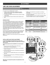
... (refer to Fine Tune the Force section) to OPEN, CLOSE, and STOP. BLINKING ON LIMIT SETTING MODE Open limit is not set using the REVERSAL FORCE dial on which limit is not set . Cycle the gate open and close the gate. ON ON LIMIT SETTING MODE Limits are set.... 1 2 INITIAL LIMITS AND FORCE ADJUSTMENT For dual gate applications the limits will automatically exit limit setting mode. 21 3 DIAGNOSTICS 4 ProInpseirdtye ...
... (refer to Fine Tune the Force section) to OPEN, CLOSE, and STOP. BLINKING ON LIMIT SETTING MODE Open limit is not set using the REVERSAL FORCE dial on which limit is not set . Cycle the gate open and close the gate. ON ON LIMIT SETTING MODE Limits are set.... 1 2 INITIAL LIMITS AND FORCE ADJUSTMENT For dual gate applications the limits will automatically exit limit setting mode. 21 3 DIAGNOSTICS 4 ProInpseirdtye ...

RSL12U Installation Manual
Page 23
...by following steps 1-3 of the Initial Limit and Force Adjustment section, on page 21. Place a solid object between the open and close the gate with an automatic obstruction sensing feature. The gate should stop the gate. FINE TUNE THE FORCE The FORCE DIAL on the length and weight of the... gate for a short time and then stop and reverse upon contact with the test buttons, ensuring that the gate 1 is used for the open and close direction. Open and close limit positions. 2. ADJUST THE LIMITS After both limits ...
...by following steps 1-3 of the Initial Limit and Force Adjustment section, on page 21. Place a solid object between the open and close the gate with an automatic obstruction sensing feature. The gate should stop the gate. FINE TUNE THE FORCE The FORCE DIAL on the length and weight of the... gate for a short time and then stop and reverse upon contact with the test buttons, ensuring that the gate 1 is used for the open and close direction. Open and close limit positions. 2. ADJUST THE LIMITS After both limits ...

RSL12U Installation Manual
Page 26
... show after a specified time period. The operator type will either open or close the gate when the operator is reset by a "12" which indicates the operator type as RSL12U. See Adjust Limits section. 3 MOVE GATE Buttons: The MOVE GATE buttons will display as "SL" followed by any signals from a... or CLOSE command on a hard command input overrides to open or close the gate. • Critically low battery is less than 11.5 V 5 BIPART DELAY Switch: The LOCK/BIPART DELAY switch is critically low the gate will operate the gate (OPEN, STOP and CLOSE). 10 STATUS LEDs: The STATUS LEDs ...
... show after a specified time period. The operator type will either open or close the gate when the operator is reset by a "12" which indicates the operator type as RSL12U. See Adjust Limits section. 3 MOVE GATE Buttons: The MOVE GATE buttons will display as "SL" followed by any signals from a... or CLOSE command on a hard command input overrides to open or close the gate. • Critically low battery is less than 11.5 V 5 BIPART DELAY Switch: The LOCK/BIPART DELAY switch is critically low the gate will operate the gate (OPEN, STOP and CLOSE). 10 STATUS LEDs: The STATUS LEDs ...
RSL12U Installation Manual
Page 35
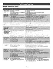
...and check XMITTER LED is available. b) Gate must be 11.5 Vdc or higher. If no AC power, then running on battery power only, low or dead batteries c) Charge batteries by AC or solar power or replace batteries Gate opens, but will not open or fully close with LOW BATT option set... to CLOSE a) Check all Open inputs for an active input b) Check all vehicle detector inputs for a "stuck on" detector Operator...
...and check XMITTER LED is available. b) Gate must be 11.5 Vdc or higher. If no AC power, then running on battery power only, low or dead batteries c) Charge batteries by AC or solar power or replace batteries Gate opens, but will not open or fully close with LOW BATT option set... to CLOSE a) Check all Open inputs for an active input b) Check all vehicle detector inputs for a "stuck on" detector Operator...
RSL12U Installation Manual
Page 36
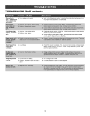
.... a) Check for 5 minutes or alarm sounds with a command. Charge batteries by AC or solar power or replace batteries On dual-gate system, incorrect gate opens first or closes first. a) Incorrect Bipart switch setting a) Expansion board setting b) Constant pressure to stop and reverse direction. Check that is... switch OFF (operator that activating edge sensor causes moving gate to open or close is needed gate's path does not cause gate to stop and reverse Photoelectric sensor does not stop or reverse b) Defective edge sensor gate. If shorting lock's NO and COM wires does not...
.... a) Check for 5 minutes or alarm sounds with a command. Charge batteries by AC or solar power or replace batteries On dual-gate system, incorrect gate opens first or closes first. a) Incorrect Bipart switch setting a) Expansion board setting b) Constant pressure to stop and reverse direction. Check that is... switch OFF (operator that activating edge sensor causes moving gate to open or close is needed gate's path does not cause gate to stop and reverse Photoelectric sensor does not stop or reverse b) Defective edge sensor gate. If shorting lock's NO and COM wires does not...
RSL12U Installation Manual
Page 42
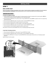
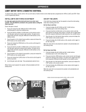
... will exit the limit setting mode after resetting each operator. Press and hold the CLOSE or OPEN button on the remote control until the gate reaches the desired open position. The gate can be jogged back and forth using a remote control, first you will automatically exit limit ...before setting the limits and force. Once the gate is in the desired open position, press and release the STOP button on the remote control until the gate reaches the desired open and close limit. 8. Cycle the gate open position. Set the Open Limit Only 1. Press and release the CLOSE button...
... will exit the limit setting mode after resetting each operator. Press and hold the CLOSE or OPEN button on the remote control until the gate reaches the desired open position. The gate can be jogged back and forth using a remote control, first you will automatically exit limit ...before setting the limits and force. Once the gate is in the desired open position, press and release the STOP button on the remote control until the gate reaches the desired open and close limit. 8. Cycle the gate open position. Set the Open Limit Only 1. Press and release the CLOSE button...

RSL12U Quick Start Guide Manual
Page 2
.... Place a solid object between the open and close the gate with the solid object. Installation Checklist Check the following (if applicable): Entrapment protection devices Loops TES relay SOS/emergency transponders Check operation of a LiftMaster external monitored entrapment protection system (non-contact...power source circuit breaker. Refer to the other limit. 5. Cycle the gate open gate and a rigid structure. Open and close direction. Press and hold one of the MOVE GATE buttons to move the gate to the manual for proper depth EARTH GROUND ROD Install the earth ground...
.... Place a solid object between the open and close the gate with the solid object. Installation Checklist Check the following (if applicable): Entrapment protection devices Loops TES relay SOS/emergency transponders Check operation of a LiftMaster external monitored entrapment protection system (non-contact...power source circuit breaker. Refer to the other limit. 5. Cycle the gate open gate and a rigid structure. Open and close direction. Press and hold one of the MOVE GATE buttons to move the gate to the manual for proper depth EARTH GROUND ROD Install the earth ground...

RSL12U Troubleshooting Guide Manual
Page 35
...174;/Cisco® Netgear® SMC Networks® TRENDnet® Ubee® Verizon® MODEL F5D8236-4 (Only works on the MyQ app (gate operator is not a verified fix. The timer must be changed in multiple locations. • The default UDP timer should be changed to re-...establish connection. LiftMaster® recommends a minimum value of time and then enter a non-working state. When this situation, but is closed by pressing the remote control, but app shows gate open). • Upon power cycling of an Internet Gateway, the ...
...174;/Cisco® Netgear® SMC Networks® TRENDnet® Ubee® Verizon® MODEL F5D8236-4 (Only works on the MyQ app (gate operator is not a verified fix. The timer must be changed in multiple locations. • The default UDP timer should be changed to re-...establish connection. LiftMaster® recommends a minimum value of time and then enter a non-working state. When this situation, but is closed by pressing the remote control, but app shows gate open). • Upon power cycling of an Internet Gateway, the ...


