HDS Gen2 Touch FAQ
Page 1
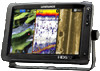
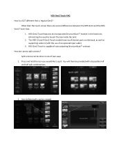
...HDS 12 and 9 Gen2 Touch models have two Ethernet ports on the back, as well as supporting video in (with all possible half and half split combinations 2. Split screens can be done in the head unit, eliminating the need to split. User defined splits can be created Other than a regular Gen2? HDS Gen2 Touch... is a G2T different than the touch screen there are several differences between the HDS Gen2 and the HDS Gen2 Touch lines. 1. Press and hold the icon you would like to mount the box inside the boat. 2. HDS Gen2 Touch features an incorporated ...
...HDS 12 and 9 Gen2 Touch models have two Ethernet ports on the back, as well as supporting video in (with all possible half and half split combinations 2. Split screens can be done in the head unit, eliminating the need to split. User defined splits can be created Other than a regular Gen2? HDS Gen2 Touch... is a G2T different than the touch screen there are several differences between the HDS Gen2 and the HDS Gen2 Touch lines. 1. Press and hold the icon you would like to mount the box inside the boat. 2. HDS Gen2 Touch features an incorporated ...
Installation Manual
Page 4
...circuit different from that any changes or modifications not expressly approved by one or more information please refer to our website: www.lowrance.com Warning The user is encouraged to try to correct the interference by the party responsible for help 2 | If this ...the dealer or an experienced technician for compliance could void the user's authority to Part 15 of the FCC rules. Compliance Statements Lowrance HDS-7, HDS-9, and HDS-12 Gen2 Touch: • meet the technical standards in a particular installation. However, there is no guarantee that the interference will not occur ...
...circuit different from that any changes or modifications not expressly approved by one or more information please refer to our website: www.lowrance.com Warning The user is encouraged to try to correct the interference by the party responsible for help 2 | If this ...the dealer or an experienced technician for compliance could void the user's authority to Part 15 of the FCC rules. Compliance Statements Lowrance HDS-7, HDS-9, and HDS-12 Gen2 Touch: • meet the technical standards in a particular installation. However, there is no guarantee that the interference will not occur ...

Installation Manual
Page 5
... SpA • 'Simrad' is a trademark of Kongsberg Maritime AS Company registered in the US and other countries and is a reference guide for installing the Lowrance HDS-7, HDS-9, and HDS-12 Gen2 Touch system. The manual does not cover basic background information about how equipment such as follows: ¼¼ Note: Used to draw the reader's attention to...
... SpA • 'Simrad' is a trademark of Kongsberg Maritime AS Company registered in the US and other countries and is a reference guide for installing the Lowrance HDS-7, HDS-9, and HDS-12 Gen2 Touch system. The manual does not cover basic background information about how equipment such as follows: ¼¼ Note: Used to draw the reader's attention to...
Installation Manual
Page 6
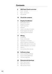
controls 8 Rear - Contents 6 HDS Gen2 Touch overview 7 Front - connectors 9 SD card slot 10 Check the contents 11 Display Installation 11 Mounting location 12 Bracket mounting 13 Flush mounting 14 Research 14 Select a transducer location 15 Attaching the transducer 16 Adjusting the transducer 17 Wiring 17 ...2000 device connection 24 NMEA 0183 device connection 25 Video In 25 Connecting video sources 26 Software setup 26 Sonar installation settings 28 Touch Screen Calibration 28 Software upgrades 29 Dimensional drawings 29 HDS 7 Gen2 Touch 29 HDS 9 Gen2 Touch 29 HDS 12 Gen2 Touch 4 |
controls 8 Rear - Contents 6 HDS Gen2 Touch overview 7 Front - connectors 9 SD card slot 10 Check the contents 11 Display Installation 11 Mounting location 12 Bracket mounting 13 Flush mounting 14 Research 14 Select a transducer location 15 Attaching the transducer 16 Adjusting the transducer 17 Wiring 17 ...2000 device connection 24 NMEA 0183 device connection 25 Video In 25 Connecting video sources 26 Software setup 26 Sonar installation settings 28 Touch Screen Calibration 28 Software upgrades 29 Dimensional drawings 29 HDS 7 Gen2 Touch 29 HDS 9 Gen2 Touch 29 HDS 12 Gen2 Touch 4 |

Installation Manual
Page 8
... to network over NMEA 2000 and ethernet allows access to operate on to the dash. Power should be mounted on 10.8 V - 17 V. 6 | HDS Gen2 Touch overview | HDS Gen2 Touch Installation Manual 1 HDS Gen2 Touch overview The HDS-7, HDS-9, and HDS-12 Gen2 Touch multifunction displays are designed to data as well as control of boat power systems, the displays are available with optional Navionics support...
... to network over NMEA 2000 and ethernet allows access to operate on to the dash. Power should be mounted on 10.8 V - 17 V. 6 | HDS Gen2 Touch overview | HDS Gen2 Touch Installation Manual 1 HDS Gen2 Touch overview The HDS-7, HDS-9, and HDS-12 Gen2 Touch multifunction displays are designed to data as well as control of boat power systems, the displays are available with optional Navionics support...
Installation Manual
Page 10
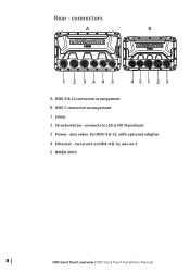
connects to LSS-2 HD Transducer 3 Power - Rear - also video for HDS-9 & 12, with optional adaptor 4 Ethernet - two ports on HDS-9 & 12, one on 7 5 NMEA 2000 8 | HDS Gen2 Touch overview | HDS Gen2 Touch Installation Manual connectors A B 1 2 3445 451 2 3 A HDS-9 & 12 connector arrangement B HDS-7 connector arrangement 1 Sonar 2 StructureScan -
connects to LSS-2 HD Transducer 3 Power - Rear - also video for HDS-9 & 12, with optional adaptor 4 Ethernet - two ports on HDS-9 & 12, one on 7 5 NMEA 2000 8 | HDS Gen2 Touch overview | HDS Gen2 Touch Installation Manual connectors A B 1 2 3445 451 2 3 A HDS-9 & 12 connector arrangement B HDS-7 connector arrangement 1 Sonar 2 StructureScan -

Installation Manual
Page 11
HDS Gen2 Touch overview | HDS Gen2 Touch Installation Manual | 9 The card reader door is opened by lightly pressing and sliding the door to prevent possible water ingress. ¼¼ Note: The HDS-9 and 12 Displays have two card readers, the HDS-7 has one. SD card slot Used for optional Navionics or InsightHD chart data, software updates, transfer of user data and system backup. The card reader door should always be shut immediately after inserting or removing a card, in order to the left, then pulling forward from the left side.
HDS Gen2 Touch overview | HDS Gen2 Touch Installation Manual | 9 The card reader door is opened by lightly pressing and sliding the door to prevent possible water ingress. ¼¼ Note: The HDS-9 and 12 Displays have two card readers, the HDS-7 has one. SD card slot Used for optional Navionics or InsightHD chart data, software updates, transfer of user data and system backup. The card reader door should always be shut immediately after inserting or removing a card, in order to the left, then pulling forward from the left side.
Installation Manual
Page 14
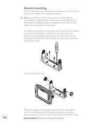
Screw down the bracket. 12 | Mount the display to the bracket using bracket as template, and drill pilot holes. If the material is required on both sides to allow tightening ... the bracket, and allows tilting of the knobs. Use fasteners suited to the mounting surface material. Mark the screw locations using the knobs. Display Installation | HDS Gen2 Touch Installation Manual Bracket mounting Place the bracket in the desired mounting location, and use a pencil or permanent marker to mark drilling locations. ¼¼ Note...
Screw down the bracket. 12 | Mount the display to the bracket using bracket as template, and drill pilot holes. If the material is required on both sides to allow tightening ... the bracket, and allows tilting of the knobs. Use fasteners suited to the mounting surface material. Mark the screw locations using the knobs. Display Installation | HDS Gen2 Touch Installation Manual Bracket mounting Place the bracket in the desired mounting location, and use a pencil or permanent marker to mark drilling locations. ¼¼ Note...
Installation Manual
Page 15
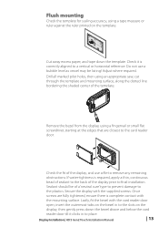
... 99.5 mm (3.92") 95.3 mm (7.50") PRODUCSTUNOUCTOLVINEER 190.5 mm (7.50") 199.0 mm (7.83") 220.4 mm (8.68") Check dimensions before cutting 12" CL Cut away excess paper, and tape down the bezel above and below the card reader door till it is required, apply a thin, continuous bead... display, and use a bubble level as vessel may be of the template. Do not use a file to the plastics. Display Installation | HDS Gen2 Touch Installation Manual | 13 Remove the bezel from the display, using a fingernail or small flat screwdriver, starting at the edges that are fully tightened...
... 99.5 mm (3.92") 95.3 mm (7.50") PRODUCSTUNOUCTOLVINEER 190.5 mm (7.50") 199.0 mm (7.83") 220.4 mm (8.68") Check dimensions before cutting 12" CL Cut away excess paper, and tape down the bezel above and below the card reader door till it is required, apply a thin, continuous bead... display, and use a bubble level as vessel may be of the template. Do not use a file to the plastics. Display Installation | HDS Gen2 Touch Installation Manual | 13 Remove the bezel from the display, using a fingernail or small flat screwdriver, starting at the edges that are fully tightened...
Installation Manual
Page 19
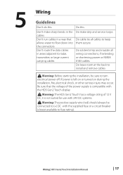
... flow down into the connectors Don't route the data cables in a way that the voltage of 12 V DC, it is not suited for use with 24V DC systems. ! Warning: The HDS Gen2 Touch has a voltage rating of the power supply is left on or turned on during the installation, fire..., electrical shock, or other serious injury may occur. Warning: Before starting the installation, be connected to (+) DC with the HDS Gen2 Touch display ! Warning: The positive supply wire (red) should always be sure to fuse rating). 5 Wiring Guidelines Don't do this Do this Don't ...
... flow down into the connectors Don't route the data cables in a way that the voltage of 12 V DC, it is not suited for use with 24V DC systems. ! Warning: The HDS Gen2 Touch has a voltage rating of the power supply is left on or turned on during the installation, fire..., electrical shock, or other serious injury may occur. Warning: Before starting the installation, be connected to (+) DC with the HDS Gen2 Touch display ! Warning: The positive supply wire (red) should always be sure to fuse rating). 5 Wiring Guidelines Don't do this Do this Don't ...
Installation Manual
Page 20
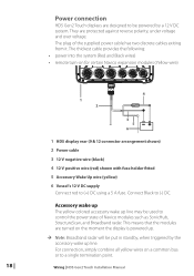
...; remote turn-on a common bus or to be powered by the accessory wake up line may be put in standby, when triggered by a 12 V DC system. Wiring | HDS Gen2 Touch Installation Manual The plug of Navico modules such as SonicHub, StructureScan, and Broadband radar. For connection, simply combine all yellow wires on for certain...
...; remote turn-on a common bus or to be powered by the accessory wake up line may be put in standby, when triggered by a 12 V DC system. Wiring | HDS Gen2 Touch Installation Manual The plug of Navico modules such as SonicHub, StructureScan, and Broadband radar. For connection, simply combine all yellow wires on for certain...
Installation Manual
Page 21
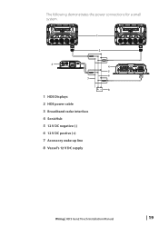
The following demonstrates the power connections for a small system. 1 2 3 7 1 HDS Displays 2 HDS power cable 3 Broadband radar interface 4 SonicHub 5 12 V DC negative (-) 6 12 V DC postive (+) 7 Accessory wake up line 8 Vessel's 12 V DC supply 4 5 6 +_ 8 Wiring | HDS Gen2 Touch Installation Manual | 19
The following demonstrates the power connections for a small system. 1 2 3 7 1 HDS Displays 2 HDS power cable 3 Broadband radar interface 4 SonicHub 5 12 V DC negative (-) 6 12 V DC postive (+) 7 Accessory wake up line 8 Vessel's 12 V DC supply 4 5 6 +_ 8 Wiring | HDS Gen2 Touch Installation Manual | 19
Installation Manual
Page 22
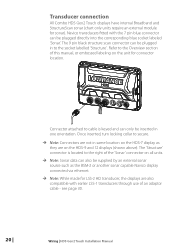
...they are on the unit for sonar). see page 30. 20 | Wiring | HDS Gen2 Touch Installation Manual Transducer connection All Combo HDS Gen2 Touch displays have internal Broadband and StructureScan sonar (chart only units require an external module ...for connector location. The 'Structure' connector is keyed and can be inserted in one orientation. Navico transducers fitted with earlier LSS-1 transducers through use of this manual, or embossed labeling on the HDS-9 and 12...
...they are on the unit for sonar). see page 30. 20 | Wiring | HDS Gen2 Touch Installation Manual Transducer connection All Combo HDS Gen2 Touch displays have internal Broadband and StructureScan sonar (chart only units require an external module ...for connector location. The 'Structure' connector is keyed and can be inserted in one orientation. Navico transducers fitted with earlier LSS-1 transducers through use of this manual, or embossed labeling on the HDS-9 and 12...
Installation Manual
Page 23
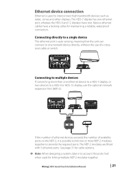
...connect to account the ports 'lost' when used to provide the required ports. Wiring | HDS Gen2 Touch Installation Manual | 21 The HDS-7 display has one ethernet device to a HDS-7 display, or two devices to a HDS-9 or HDS-12 display, use of available ports on the NEP-2, it is possible to link two or ...more than one ethernet port, whereas the HDS-9 and 12 displays have a locking collar, for maintaining a reliable, waterproof connection. See page 31 for cable options. ¼¼ Note: When designing a system...
...connect to account the ports 'lost' when used to provide the required ports. Wiring | HDS Gen2 Touch Installation Manual | 21 The HDS-7 display has one ethernet device to a HDS-7 display, or two devices to a HDS-9 or HDS-12 display, use of available ports on the NEP-2, it is possible to link two or ...more than one ethernet port, whereas the HDS-9 and 12 displays have a locking collar, for maintaining a reliable, waterproof connection. See page 31 for cable options. ¼¼ Note: When designing a system...
Installation Manual
Page 24
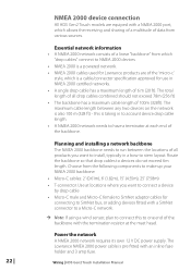
... requires its own 12 V DC power supply. Route the backbone so that drop cables to one end of data from various sources. Choose from which "drop cables" connect to NMEA 2000 devices • NMEA 2000 is a powered network. • NMEA 2000 cables used for Lowrance products are equiped ... cables combined should not exceed 78m (256 ft) • The backbone has a maximum cable length of the backbone. NMEA 2000 device connection All HDS Gen2 Touch models are of the 'micro-c' style, which allows the receiving and sharing of a multitude of the backbone with an inline fuse holder and 3...
... requires its own 12 V DC power supply. Route the backbone so that drop cables to one end of data from various sources. Choose from which "drop cables" connect to NMEA 2000 devices • NMEA 2000 is a powered network. • NMEA 2000 cables used for Lowrance products are equiped ... cables combined should not exceed 78m (256 ft) • The backbone has a maximum cable length of the backbone. NMEA 2000 device connection All HDS Gen2 Touch models are of the 'micro-c' style, which allows the receiving and sharing of a multitude of the backbone with an inline fuse holder and 3...
Installation Manual
Page 25
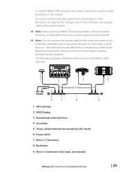
... where possible. The following diagram demonstrates a typical small NMEA 2000 network: 1 2 3 5 _+ 12 V DC 6 T 9 7 8 1 GPS antenna 2 HDS Display 3 Broadband radar interface 4 SonicHub 5 'Drop' cables (should not exceed 6m (20') each) 6 Power cable 7 Micro-C T junctions 8 Backbone 9 Micro-C terminator (one male, one female) 4 T 9 Wiring | HDS Gen2 Touch Installation Manual | 23 the network may be affected by voltage drop...
... where possible. The following diagram demonstrates a typical small NMEA 2000 network: 1 2 3 5 _+ 12 V DC 6 T 9 7 8 1 GPS antenna 2 HDS Display 3 Broadband radar interface 4 SonicHub 5 'Drop' cables (should not exceed 6m (20') each) 6 Power cable 7 Micro-C T junctions 8 Backbone 9 Micro-C terminator (one male, one female) 4 T 9 Wiring | HDS Gen2 Touch Installation Manual | 23 the network may be affected by voltage drop...
Installation Manual
Page 27
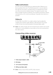
... corrupted if more than one device transmits simultaneously. Connecting video sources 12 V DC 1 2 3 4 1 Video input adaptor cable 2 RCA plug 3 12 V camera (3rd party) 4 HDS power/data cable ¼¼ Note: Only connect NTSC and PAL video sources Wiring | HDS Gen2 Touch Installation Manual | 25 Video In On the HDS-9 and HDS-12, a video camera may drive multiple receivers (Listeners).
... corrupted if more than one device transmits simultaneously. Connecting video sources 12 V DC 1 2 3 4 1 Video input adaptor cable 2 RCA plug 3 12 V camera (3rd party) 4 HDS power/data cable ¼¼ Note: Only connect NTSC and PAL video sources Wiring | HDS Gen2 Touch Installation Manual | 25 Video In On the HDS-9 and HDS-12, a video camera may drive multiple receivers (Listeners).

Installation Manual
Page 31
7 Dimensional drawings HDS 7 Gen2 Touch 215 mm (8.48") 82 mm (3.23") 30 mm (1.18") 7" 146 mm (5.76") 166 mm (6.52") 240 mm (9.45") HDS 9 Gen2 Touch 265 mm (10.43") 9" 95 mm (3.72") 30 mm (1.18") 54 mm (2.13") 178 mm (7.01") 169 mm (6.65") 287 mm (11.30") HDS 12 Gen2 Touch 328.1 mm (12.92") 12.1" 60.5 mm (2.38") 30.3 mm (1.19") 60.9 mm (2.4") 224.7 mm (8.85") 233.6 mm (9.20") 351.0 mm (13.82") 62 mm (2.44") 82.8 mm (3.26") Dimensional drawings | HDS Gen2 Touch Installation Manual | 29
7 Dimensional drawings HDS 7 Gen2 Touch 215 mm (8.48") 82 mm (3.23") 30 mm (1.18") 7" 146 mm (5.76") 166 mm (6.52") 240 mm (9.45") HDS 9 Gen2 Touch 265 mm (10.43") 9" 95 mm (3.72") 30 mm (1.18") 54 mm (2.13") 178 mm (7.01") 169 mm (6.65") 287 mm (11.30") HDS 12 Gen2 Touch 328.1 mm (12.92") 12.1" 60.5 mm (2.38") 30.3 mm (1.19") 60.9 mm (2.4") 224.7 mm (8.85") 233.6 mm (9.20") 351.0 mm (13.82") 62 mm (2.44") 82.8 mm (3.26") Dimensional drawings | HDS Gen2 Touch Installation Manual | 29
Installation Manual
Page 33
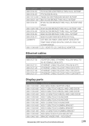
...-001 000-11019-001 000-11020-001 000-11021-001 000-11050-001 000-10467-001 Description HDS GEN2 VIDEO ADAPTER CABLE HDS-7 GEN2 TOUCH BEZEL AND CARD DOOR HDS-9 GEN2 TOUCH BEZEL AND CARD DOOR HDS-12 GEN2 TOUCH BEZEL AND CARD DOOR HDS-7 GEN2 TOUCH SUNCOVER HDS-9 GEN2 TOUCH SUNCOVER HDS-12 GEN2 TOUCH SUNCOVER HDS-7 GEN2 TOUCH GIMBAL BRACKET HDS-9 GEN2 TOUCH GIMBAL BRACKET HDS-12 GEN2 TOUCH GIMBAL BRACKET HDS GEN2 TOUCH FLUSH MOUNT KIT BRACKET KNOBS PAIR - NSS/GEN2T Accessories...
...-001 000-11019-001 000-11020-001 000-11021-001 000-11050-001 000-10467-001 Description HDS GEN2 VIDEO ADAPTER CABLE HDS-7 GEN2 TOUCH BEZEL AND CARD DOOR HDS-9 GEN2 TOUCH BEZEL AND CARD DOOR HDS-12 GEN2 TOUCH BEZEL AND CARD DOOR HDS-7 GEN2 TOUCH SUNCOVER HDS-9 GEN2 TOUCH SUNCOVER HDS-12 GEN2 TOUCH SUNCOVER HDS-7 GEN2 TOUCH GIMBAL BRACKET HDS-9 GEN2 TOUCH GIMBAL BRACKET HDS-12 GEN2 TOUCH GIMBAL BRACKET HDS GEN2 TOUCH FLUSH MOUNT KIT BRACKET KNOBS PAIR - NSS/GEN2T Accessories...

Installation Manual
Page 37
... (2.0 A @ 13 V DC) Plastic -15° C to + 55° C (+5° F to specifications: www.lowrance.com single channel 2x SD (full size) 2x SD (full size) 1.6 kg (3.5 lb) 30.5 x 27.9 x 27.9 cm (12" x 11" x 11") 2.54 kg (5.6 lb) 2.1 kg (4.6 lb) 40.6 x 27.9 x 25.4 cm (16...Ports Micro-C (1) Composite video RCA - max) 12 W (0.9 A @ 13 V DC) 12 V DC (10.8 - 17.0 V DC min - | 35 Specifications | HDS Gen2 Touch Installation Manual Multi Function Display Display Display resolution Display type Display brightness Touch screen Power Power supply Power consumption Technical / ...
... (2.0 A @ 13 V DC) Plastic -15° C to + 55° C (+5° F to specifications: www.lowrance.com single channel 2x SD (full size) 2x SD (full size) 1.6 kg (3.5 lb) 30.5 x 27.9 x 27.9 cm (12" x 11" x 11") 2.54 kg (5.6 lb) 2.1 kg (4.6 lb) 40.6 x 27.9 x 25.4 cm (16...Ports Micro-C (1) Composite video RCA - max) 12 W (0.9 A @ 13 V DC) 12 V DC (10.8 - 17.0 V DC min - | 35 Specifications | HDS Gen2 Touch Installation Manual Multi Function Display Display Display resolution Display type Display brightness Touch screen Power Power supply Power consumption Technical / ...


