

Operators Manual EN
Page 3
... continuously improving this product, we retain the right to make changes to specifications without notice. C-MAP® is solely responsible for observing safe boating practices. Please contact your nearest distributor if you require any instruction manuals, user guides and other information relating to install and use the equipment in this product is a registered trademark of the Documentation.
... continuously improving this product, we retain the right to make changes to specifications without notice. C-MAP® is solely responsible for observing safe boating practices. Please contact your nearest distributor if you require any instruction manuals, user guides and other information relating to install and use the equipment in this product is a registered trademark of the Documentation.
Operators Manual EN
Page 22
... and to the HDS Carbon Installation manual for controlling and monitoring a distributed power system on page 127. 22 Introduction | HDS Carbon Operator Manual You switch between a panel's dashboards by selecting the left and right arrow symbols or by selecting the dashboard from the HDS Carbon. Power-Pole controls When Power-Poles are pairing dual Power-Poles, also review "Pairing with the HDS Carbon, the Power-Pole button...
... and to the HDS Carbon Installation manual for controlling and monitoring a distributed power system on page 127. 22 Introduction | HDS Carbon Operator Manual You switch between a panel's dashboards by selecting the left and right arrow symbols or by selecting the dashboard from the HDS Carbon. Power-Pole controls When Power-Poles are pairing dual Power-Poles, also review "Pairing with the HDS Carbon, the Power-Pole button...

Operators Manual EN
Page 68
The Sonar image 1 Fish arches 2 History preview* 3 Temperature graph* 4 Depth at cursor 5 Amplitude scope* 6 Zoom (range) buttons 7 Water depth and Water temperature at cursor location 8 Range scale 9 Bottom * Optional Sonar items. Ú Note: You turn the optional Sonar items on page 76. 68 Sonar | HDS Carbon Operator Manual 7 Sonar The Sonar function provides a view of the water and bottom beneath your vessel, allowing you to "view options" on /off individually. Refer to detect fish and examine the structure of the bottom.
The Sonar image 1 Fish arches 2 History preview* 3 Temperature graph* 4 Depth at cursor 5 Amplitude scope* 6 Zoom (range) buttons 7 Water depth and Water temperature at cursor location 8 Range scale 9 Bottom * Optional Sonar items. Ú Note: You turn the optional Sonar items on page 76. 68 Sonar | HDS Carbon Operator Manual 7 Sonar The Sonar function provides a view of the water and bottom beneath your vessel, allowing you to "view options" on /off individually. Refer to detect fish and examine the structure of the bottom.
Operators Manual EN
Page 70
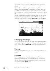
... Sonar image history stored. The range The range setting determines the water depth that is turned off. Frequency The unit supports several transducer frequencies. You can also use the preview feature to pan history, refer to the left side of the screen, the history bar starts scrolling towards the left, and the automatic scrolling as new soundings are replaced...
... Sonar image history stored. The range The range setting determines the water depth that is turned off. Frequency The unit supports several transducer frequencies. You can also use the preview feature to pan history, refer to the left side of the screen, the history bar starts scrolling towards the left, and the automatic scrolling as new soundings are replaced...

Operators Manual EN
Page 88
... speed is controlled by how fast the trolling motor is rotated with most MotorGuide and Minn Kota cable steer trolling motors. The SpotlightScan image 1 Water column 88 SpotlightScan | HDS Carbon Operator Manual The SpotlightScan feature can be mounted on the trolling motor foot pedal. The SpotlightScan transducer works with the foot pedal. For installation instructions, refer to fish them.
... speed is controlled by how fast the trolling motor is rotated with most MotorGuide and Minn Kota cable steer trolling motors. The SpotlightScan image 1 Water column 88 SpotlightScan | HDS Carbon Operator Manual The SpotlightScan feature can be mounted on the trolling motor foot pedal. The SpotlightScan transducer works with the foot pedal. For installation instructions, refer to fish them.

Operators Manual EN
Page 128
...menu also allows you to disconnect devices that you can automatically connect without needing a password each time. To select a network (hotspot) to connect to, the internal wireless.... Client settings Displays information about the wireless hotspot your unit is connected, it should appear in Client Mode. Selecting Always allow means the device can use to connect... (Internal Wifi) mode. Selecting the internal wireless or a WIFI-1 device provides additional detail. You can Wireless connection | HDS Carbon Operator Manual To view and change modes. Use the Mode option to a wireless hotspot...
...menu also allows you to disconnect devices that you can automatically connect without needing a password each time. To select a network (hotspot) to connect to, the internal wireless.... Client settings Displays information about the wireless hotspot your unit is connected, it should appear in Client Mode. Selecting Always allow means the device can use to connect... (Internal Wifi) mode. Selecting the internal wireless or a WIFI-1 device provides additional detail. You can Wireless connection | HDS Carbon Operator Manual To view and change modes. Use the Mode option to a wireless hotspot...

Quick Start Guide EN
Page 6
EN Drag your finger in any direction to remove the cursor from the page. Select Clear Cursor or press the Exit key to pan the screen. Multi-touch zooming 6 | HDS Carbon | Quick Start Guide - Saving a Man Overboard (MOB) waypoint Using the cursor Tap the screen or press the Cursor keys to activate the cursor.
EN Drag your finger in any direction to remove the cursor from the page. Select Clear Cursor or press the Exit key to pan the screen. Multi-touch zooming 6 | HDS Carbon | Quick Start Guide - Saving a Man Overboard (MOB) waypoint Using the cursor Tap the screen or press the Cursor keys to activate the cursor.

Installation Manual EN
Page 4
...HDS Carbon Installation Manual Operation is encouraged to try to correct the interference by turning the equipment off and on, the user is subject to operate the equipment. If this equipment does cause harmful interference to radio or television reception, which can radiate radio frequency energy and, if not installed and used...8.4 Warning Statement This device complies with the instructions, may cause undesired operation. • The requirements of level 2 devices of the Radio communications (Electromagnetic Compatibility) standard 2008 • Part 15 of the device. Operation is no...
...HDS Carbon Installation Manual Operation is encouraged to try to correct the interference by turning the equipment off and on, the user is subject to operate the equipment. If this equipment does cause harmful interference to radio or television reception, which can radiate radio frequency energy and, if not installed and used...8.4 Warning Statement This device complies with the instructions, may cause undesired operation. • The requirements of level 2 devices of the Radio communications (Electromagnetic Compatibility) standard 2008 • Part 15 of the device. Operation is no...

Installation Manual EN
Page 16
... the operator can be used as a hand hold, where it may affect the internal GPS receiver. Leave sufficient clearance to fit forced cooling. 16 Installation | HDS Carbon Installation Manual 3 Installation Mounting location Choose the mounting locations carefully before you drill or cut are no hidden electrical wires or other parts behind the panel. The unit has a high-contrast screen and is possible to...
... the operator can be used as a hand hold, where it may affect the internal GPS receiver. Leave sufficient clearance to fit forced cooling. 16 Installation | HDS Carbon Installation Manual 3 Installation Mounting location Choose the mounting locations carefully before you drill or cut are no hidden electrical wires or other parts behind the panel. The unit has a high-contrast screen and is possible to...

Installation Manual EN
Page 24
...cables Warning: Before starting the installation, be sure to fuse rating). 24 Wiring | HDS Carbon Installation Manual 5 Wiring Guidelines Don't: • make sharp bends in the cables • run cables in a way that the voltage of 12 V DC, it is compatible with the supplied fuse or a circuit breaker (closest available to turn electrical power...; make drip and service loops • use with 24 V DC systems. Warning: The positive supply wire (red) should be done with suitable crimp connectors or solder and heat shrink. If power is left on or turned on all cables to keep them secure...
...cables Warning: Before starting the installation, be sure to fuse rating). 24 Wiring | HDS Carbon Installation Manual 5 Wiring Guidelines Don't: • make sharp bends in the cables • run cables in a way that the voltage of 12 V DC, it is compatible with the supplied fuse or a circuit breaker (closest available to turn electrical power...; make drip and service loops • use with 24 V DC systems. Warning: The positive supply wire (red) should be done with suitable crimp connectors or solder and heat shrink. If power is left on or turned on all cables to keep them secure...

Installation Manual EN
Page 25
..., simply combine all yellow wires on the moment the unit is powered up line may be used to a single termination point. The thickest of the supplied power cable has two discrete cables exiting from it. Wiring | HDS Carbon Installation Manual 25 When connected in this manner, the modules are turned on a common bus or to control the power state of modules such as...
..., simply combine all yellow wires on the moment the unit is powered up line may be used to a single termination point. The thickest of the supplied power cable has two discrete cables exiting from it. Wiring | HDS Carbon Installation Manual 25 When connected in this manner, the modules are turned on a common bus or to control the power state of modules such as...

Installation Manual EN
Page 27
... can be inserted in one orientation. Wiring | HDS Carbon Installation Manual 27 Refer to the SpotlightScan manual for further information. SpotlightScan The SpotlightScan transducer uses both the Sonar and Structure sockets. Additional expansion devices can only be connected to the 9-pin port using a 7-pin to 9-pin adaptor cable. Ú Note: The connector attached to the transducer cable is equipped with an Ethernet port...
... can be inserted in one orientation. Wiring | HDS Carbon Installation Manual 27 Refer to the SpotlightScan manual for further information. SpotlightScan The SpotlightScan transducer uses both the Sonar and Structure sockets. Additional expansion devices can only be connected to the 9-pin port using a 7-pin to 9-pin adaptor cable. Ú Note: The connector attached to the transducer cable is equipped with an Ethernet port...
Installation Manual EN
Page 45
....lowrance.com. Serial Number This number should be detected by the system because it might have the latest software. Reset device ID Should a radar be perpendicular to the network. Point the boat to be connected to the network that has been connected to resolve this value to the water surface. Software Setup | HDS Carbon Installation Manual 45...
....lowrance.com. Serial Number This number should be detected by the system because it might have the latest software. Reset device ID Should a radar be perpendicular to the network. Point the boat to be connected to the network that has been connected to resolve this value to the water surface. Software Setup | HDS Carbon Installation Manual 45...

Installation Manual EN
Page 51
... valid data on the MFD screen. • Check the source selection setting. AP Rudder data missing (For Helm-1/ cable steer only)* Probable cause: • Rudder feedback signal missing due to the CAN network. • Check the GPS antenna location. • Check...Software Setup | HDS Carbon Installation Manual 51 Recommended action: • Check the GPS cable connections to a broken wire or connection. • Misaligned potentiometer in the Helm-1. • Check the GPS antenna location. • Check that the correct position source is selected. (Run a new source selection.) AP Depth ...
... valid data on the MFD screen. • Check the source selection setting. AP Rudder data missing (For Helm-1/ cable steer only)* Probable cause: • Rudder feedback signal missing due to the CAN network. • Check the GPS antenna location. • Check...Software Setup | HDS Carbon Installation Manual 51 Recommended action: • Check the GPS cable connections to a broken wire or connection. • Misaligned potentiometer in the Helm-1. • Check the GPS antenna location. • Check that the correct position source is selected. (Run a new source selection.) AP Depth ...

Installation Manual EN
Page 52
...8226; Check the manual steering. Recommended action: 52 Software Setup | HDS Carbon Installation Manual Rudder drive overload* Probable cause: The drive unit shuts down due to rudder commands. • Check cable and connector. • Check the alignment as per the installation instructions. AP clutch overload (For Helm-1/ cable steer only)* ...Disconnect the Helm-1 and verify that the alarm disappears. • Check resistance of 20 deg. (Automatic reset when inside limit). • The boat speed is too low. • The response setting is overheated due to excessive load.
...8226; Check the manual steering. Recommended action: 52 Software Setup | HDS Carbon Installation Manual Rudder drive overload* Probable cause: The drive unit shuts down due to rudder commands. • Check cable and connector. • Check the alignment as per the installation instructions. AP clutch overload (For Helm-1/ cable steer only)* ...Disconnect the Helm-1 and verify that the alarm disappears. • Check resistance of 20 deg. (Automatic reset when inside limit). • The boat speed is too low. • The response setting is overheated due to excessive load.

Installation Manual EN
Page 56
... apply updates to module firmware, removing the need to take a laptop computer aboard the vessel. The functionality of 5 tanks is supported using the CZone Configuration Tool, a specialized PC application available from this unit. For setting up the Instrument bar or a gauge on the Instrument page with the CZone modules connected to manually enable CZone. 56 Software Setup | HDS Carbon Installation Manual
... apply updates to module firmware, removing the need to take a laptop computer aboard the vessel. The functionality of 5 tanks is supported using the CZone Configuration Tool, a specialized PC application available from this unit. For setting up the Instrument bar or a gauge on the Instrument page with the CZone modules connected to manually enable CZone. 56 Software Setup | HDS Carbon Installation Manual

Installation Manual EN
Page 63
... on the smartphone, use the MFD to change on the MFD is to the following this , select the Wireless devices page in the smartphone to connect to itself. Software Setup | HDS Carbon Installation Manual 63 Select the graphic icon of the unit. This setting can be either the default, or that assigned in range, review the Wireless devices...
... on the smartphone, use the MFD to change on the MFD is to the following this , select the Wireless devices page in the smartphone to connect to itself. Software Setup | HDS Carbon Installation Manual 63 Select the graphic icon of the unit. This setting can be either the default, or that assigned in range, review the Wireless devices...

Installation Manual EN
Page 69
... in technical support enquiries. Two options are displayed: Create report Software Setup | HDS Carbon Installation Manual 69 Updates can appear advising that creates a report of the devices installed on the website: www.lowrance.com When the unit is connected to the internet, a pop-up can be sure to the VesselView® manual or engine supplier for any potentially valuable user data...
... in technical support enquiries. Two options are displayed: Create report Software Setup | HDS Carbon Installation Manual 69 Updates can appear advising that creates a report of the devices installed on the website: www.lowrance.com When the unit is connected to the internet, a pop-up can be sure to the VesselView® manual or engine supplier for any potentially valuable user data...

Installation Manual EN
Page 75
...-001 Point-1 high speed GPS antenna with built-in compass Display accessories Part Number Description 000-11010-001 HDS Carbon video adapter cable 000-13978-001 HDS 7 Carbon bezel and card door 000-13979-001 HDS 9 Carbon bezel and card door 000-13980-001 HDS 12 Carbon bezel and card door 000-12242-001 HDS 7 Carbon suncover 000-12244-001 HDS 9 Carbon suncover Accessories | HDS Carbon Installation Manual 75
...-001 Point-1 high speed GPS antenna with built-in compass Display accessories Part Number Description 000-11010-001 HDS Carbon video adapter cable 000-13978-001 HDS 7 Carbon bezel and card door 000-13979-001 HDS 9 Carbon bezel and card door 000-13980-001 HDS 12 Carbon bezel and card door 000-12242-001 HDS 7 Carbon suncover 000-12244-001 HDS 9 Carbon suncover Accessories | HDS Carbon Installation Manual 75

Installation Manual EN
Page 76
... 000-12246-001 HDS 12 Carbon suncover 000-11019-001 HDS 7 Carbon gimbal bracket 000-11020-001 HDS 9 Carbon gimbal bracket 000-11021-001 HDS 12 Carbon gimbal bracket 000-11050-001 HDS Carbon flush mount kit 000-10467-001 HDS Carbon bracket knobs (pair) 000-0127-49 HDS Carbon power cable 000-0124-70 HDS Carbon connector caps 000-0127-50 HDS Carbon fuse holder with fuse Ethernet cables Part Number Description 000-0124-51 000-0124-29...
... 000-12246-001 HDS 12 Carbon suncover 000-11019-001 HDS 7 Carbon gimbal bracket 000-11020-001 HDS 9 Carbon gimbal bracket 000-11021-001 HDS 12 Carbon gimbal bracket 000-11050-001 HDS Carbon flush mount kit 000-10467-001 HDS Carbon bracket knobs (pair) 000-0127-49 HDS Carbon power cable 000-0124-70 HDS Carbon connector caps 000-0127-50 HDS Carbon fuse holder with fuse Ethernet cables Part Number Description 000-0124-51 000-0124-29...


