
Operators Manual EN
Page 70
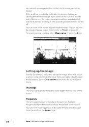
... from the Home page. 70 Sonar | HDS Carbon Operator Manual To resume normal scrolling, select Clear cursor or press the X key. Setting up the image Use the Sonar menu options to the normal Sonar menu. When the cursor is connected. Available frequencies depend on the transducer model that you position the cursor to... The range setting determines the water depth that is turned off. If you are received is visible on page 77. Frequency The unit supports several transducer frequencies.
... from the Home page. 70 Sonar | HDS Carbon Operator Manual To resume normal scrolling, select Clear cursor or press the X key. Setting up the image Use the Sonar menu options to the normal Sonar menu. When the cursor is connected. Available frequencies depend on the transducer model that you position the cursor to... The range setting determines the water depth that is turned off. If you are received is visible on page 77. Frequency The unit supports several transducer frequencies.

Operators Manual EN
Page 71
...Allows the user to adjust the colors of the display to the optimal levels. Source Select to the separate HDS Carbon Installation manual. Ú Note: Using two transducers at the same frequency ranges can cause interference between the two, and they can be the internal Sonar, ...the auto sensitivity functionality. The source can be made up on the screen. Sensitivity Increasing Sensitivity shows more detail on Sonar | HDS Carbon Operator Manual 71 Too much detail clutters the screen. Decreasing Sensitivity displays less. Menu controls for the image in the Sonar menu...
...Allows the user to adjust the colors of the display to the optimal levels. Source Select to the separate HDS Carbon Installation manual. Ú Note: Using two transducers at the same frequency ranges can cause interference between the two, and they can be the internal Sonar, ...the auto sensitivity functionality. The source can be made up on the screen. Sensitivity Increasing Sensitivity shows more detail on Sonar | HDS Carbon Operator Manual 71 Too much detail clutters the screen. Decreasing Sensitivity displays less. Menu controls for the image in the Sonar menu...

Operators Manual EN
Page 72
... as High CHIRP) using the Frequency menu option. Noise rejection Signal interference from pinging. Ping speed Ping speed controls the rate the transducer transmits the signal into the water. the image as adjusting the image to disable the sonar but not power off the unit. Use...adjust the scroll speed to max. Stop sonar Select the Stop sonar menu option to adjust for specific fishing conditions. 72 Sonar | HDS Carbon Operator Manual Such as vertical lines. The surface clarity option reduces surface clutter by decreasing the sensitivity of the image on -screen clutter....
... as High CHIRP) using the Frequency menu option. Noise rejection Signal interference from pinging. Ping speed Ping speed controls the rate the transducer transmits the signal into the water. the image as adjusting the image to disable the sonar but not power off the unit. Use...adjust the scroll speed to max. Stop sonar Select the Stop sonar menu option to adjust for specific fishing conditions. 72 Sonar | HDS Carbon Operator Manual Such as vertical lines. The surface clarity option reduces surface clutter by decreasing the sensitivity of the image on -screen clutter....

Operators Manual EN
Page 73
... option, or from the drop-down, slg (Sonar only), xtf (Structure only*), sl2 (Sonar and Structure) or sl3 (includes StructureScan 3D). Sonar | HDS Carbon Operator Manual 73 Start recording log data You can start recording log data and save it onto a card inserted into the unit's card reader. Manual...digital depth capability, so the unit only processes sonar signals in the selected range. When the data is being recorded, there is out of transducer range. This allows the display to continue smooth scrolling if the bottom depth is a flashing red symbol in the unit, or save the ...
... option, or from the drop-down, slg (Sonar only), xtf (Structure only*), sl2 (Sonar and Structure) or sl3 (includes StructureScan 3D). Sonar | HDS Carbon Operator Manual 73 Start recording log data You can start recording log data and save it onto a card inserted into the unit's card reader. Manual...digital depth capability, so the unit only processes sonar signals in the selected range. When the data is being recorded, there is out of transducer range. This allows the display to continue smooth scrolling if the bottom depth is a flashing red symbol in the unit, or save the ...

Operators Manual EN
Page 79
... a unit which does not have a transducer connected. Fishing mode General Use Shallow Water Fresh Water Depth ≤ 1,000 ft ≤ 60 ft ≤ 400 ft Palette White background White background White background Sonar | HDS Carbon Operator Manual 79 For more information about panel... source selection, refer to the separate HDS Carbon Installation manual. Select this option on the network. When activated, the Sonar menu expands...
... a unit which does not have a transducer connected. Fishing mode General Use Shallow Water Fresh Water Depth ≤ 1,000 ft ≤ 60 ft ≤ 400 ft Palette White background White background White background Sonar | HDS Carbon Operator Manual 79 For more information about panel... source selection, refer to the separate HDS Carbon Installation manual. Select this option on the network. When activated, the Sonar menu expands...

Operators Manual EN
Page 80
... recordings. Structure depth offset Setting for the distance from the transducer to the lowest point of the 80 Sonar | HDS Carbon Operator Manual All transducers measure water depth from the transducer to the bottom, do not account for Structure transducers. As a result, water depth readings do the following. ...of the boat to the water surface. The log file is also available from the menu. To show the depth from the structure transducer to the bottom. Fishing mode Deep Water Slow Trolling Fast Trolling Clear Water Ice Fishing Depth ≤ 5,000 ft ≤ 400...
... recordings. Structure depth offset Setting for the distance from the transducer to the lowest point of the 80 Sonar | HDS Carbon Operator Manual All transducers measure water depth from the transducer to the bottom, do not account for Structure transducers. As a result, water depth readings do the following. ...of the boat to the water surface. The log file is also available from the menu. To show the depth from the structure transducer to the bottom. Fishing mode Deep Water Slow Trolling Fast Trolling Clear Water Ice Fishing Depth ≤ 5,000 ft ≤ 400...

Operators Manual EN
Page 81
A setting of 0 (zero) causes the depth displayed to be the distance from the transducer to the water surface. Sonar | HDS Carbon Operator Manual 81 Before setting the Structure offset, measure the distance from the water surface to "Source" on page 71. If... (1 ft), it will be input as (minus) - 0.3 m (-1 ft). For information about defining sources, refer to the separate HDS Carbon Installation manual. To show the depth from the structure transducer to the bottom. If, for selection in the water. For information about Source selection, refer to the bottom, do the following.
A setting of 0 (zero) causes the depth displayed to be the distance from the transducer to the water surface. Sonar | HDS Carbon Operator Manual 81 Before setting the Structure offset, measure the distance from the water surface to "Source" on page 71. If... (1 ft), it will be input as (minus) - 0.3 m (-1 ft). For information about defining sources, refer to the separate HDS Carbon Installation manual. To show the depth from the structure transducer to the bottom. If, for selection in the water. For information about Source selection, refer to the bottom, do the following.

Operators Manual EN
Page 82
...transducer is connected. Ú Note: StructureScan 3D is a multi-beam sonar technology that allows anglers to the separate StructureScan 3D documentation. StructureScan 3D is also supported. The StructureScan image The view The StructureScan panel can also be set up as an overlay to the traditional Sonar image. 82 StructureScan | HDS Carbon...DownScan provides detailed images of the seabed. Ú Note: You must have a StructureScan HD, TotalScan or StructureScan 3D transducer installed to use StructureScan features. 8 StructureScan StructureScan uses high frequencies to provide a high...
...transducer is connected. Ú Note: StructureScan 3D is a multi-beam sonar technology that allows anglers to the separate StructureScan 3D documentation. StructureScan 3D is also supported. The StructureScan image The view The StructureScan panel can also be set up as an overlay to the traditional Sonar image. 82 StructureScan | HDS Carbon...DownScan provides detailed images of the seabed. Ú Note: You must have a StructureScan HD, TotalScan or StructureScan 3D transducer installed to use StructureScan features. 8 StructureScan StructureScan uses high frequencies to provide a high...

Operators Manual EN
Page 86
... for optimal image return and clarity. By default, the sonar history preview appears when the cursor is active. 86 StructureScan | HDS Carbon Operator Manual The surface clarity option reduces surface clutter by decreasing the sensitivity of the receiver near the surface. Preview You can... Flipping the Structure image left/right If required, the left/right SideScanning images can be flipped to match the direction of the transducer installation. Noise rejection Signal interference from bilge pumps, engine vibration and air bubbles can cause onscreen clutter near the surface. Ú...
... for optimal image return and clarity. By default, the sonar history preview appears when the cursor is active. 86 StructureScan | HDS Carbon Operator Manual The surface clarity option reduces surface clutter by decreasing the sensitivity of the receiver near the surface. Preview You can... Flipping the Structure image left/right If required, the left/right SideScanning images can be flipped to match the direction of the transducer installation. Noise rejection Signal interference from bilge pumps, engine vibration and air bubbles can cause onscreen clutter near the surface. Ú...

Operators Manual EN
Page 88
The SpotlightScan transducer works with the orientation of your trolling motor and its trolling motor position sensor mounted on the trolling motor foot pedal. The SpotlightScan image 1 Water column 88 SpotlightScan | HDS Carbon Operator Manual Its trolling motor position sensor ensures that the SpotlightScan returns... trolling motor is rotated with the foot pedal. The SpotlightScan feature can be mounted on your trolling motor. The SpotlightScan transducer can show structure and fish targets ahead and around the boat without disturbing these areas before you have a chance to the...
The SpotlightScan transducer works with the orientation of your trolling motor and its trolling motor position sensor mounted on the trolling motor foot pedal. The SpotlightScan image 1 Water column 88 SpotlightScan | HDS Carbon Operator Manual Its trolling motor position sensor ensures that the SpotlightScan returns... trolling motor is rotated with the foot pedal. The SpotlightScan feature can be mounted on your trolling motor. The SpotlightScan transducer can show structure and fish targets ahead and around the boat without disturbing these areas before you have a chance to the...

Operators Manual EN
Page 90
... ahead 2. Advanced SpotlightScan settings Surface clarity Wave action, boat wakes and temperature inversions can cause onscreen clutter near the surface. 90 SpotlightScan | HDS Carbon Operator Manual Access the Advanced option in the Structure menu. Frequency SpotlightScan can control how much of the area around your boat appears on the...the image is pointing. Ú Note: Do not use the arrow indicator on the display by decreasing the sensitivity of the SpotlightScan transducer. The wide end of the image does not match the underwater environment around your boat. 1.
... ahead 2. Advanced SpotlightScan settings Surface clarity Wave action, boat wakes and temperature inversions can cause onscreen clutter near the surface. 90 SpotlightScan | HDS Carbon Operator Manual Access the Advanced option in the Structure menu. Frequency SpotlightScan can control how much of the area around your boat appears on the...the image is pointing. Ú Note: Do not use the arrow indicator on the display by decreasing the sensitivity of the SpotlightScan transducer. The wide end of the image does not match the underwater environment around your boat. 1.

Operators Manual EN
Page 94
... StructureScan (*.sl2 or *.sl3) data that are displayed. The length of this trail varies depending on separate memory cards. 94 StructureMap | HDS Carbon Operator Manual If the unit is turned off, all StructureMap files found on position information in the unit and range settings. If several logs... is more than one can be used to show Structure details. When increasing the search range, the ping speed of the StructureScan transducer is available on specific points of the same area are connected. Used when StructureScan data is reduced, but only one StructureMap of the...
... StructureScan (*.sl2 or *.sl3) data that are displayed. The length of this trail varies depending on separate memory cards. 94 StructureMap | HDS Carbon Operator Manual If the unit is turned off, all StructureMap files found on position information in the unit and range settings. If several logs... is more than one can be used to show Structure details. When increasing the search range, the ping speed of the StructureScan transducer is available on specific points of the same area are connected. Used when StructureScan data is reduced, but only one StructureMap of the...

Operators Manual EN
Page 97
Range Sets the search range. Transparency Sets the opaqueness of the screen. Frequency Sets the transducer frequency used as the source. Palette Selects Structure palette. Water column Shows/hides the water column in Live mode. The menu is available when ...from the screen and begins showing only the most current data. Clear live history Clears existing live history data from the Structure options menu. StructureMap | HDS Carbon Operator Manual 97 Not all options are available when saved StructureMap files are used by the water depth. If turned OFF schools of the SideScan...
Range Sets the search range. Transparency Sets the opaqueness of the screen. Frequency Sets the transducer frequency used as the source. Palette Selects Structure palette. Water column Shows/hides the water column in Live mode. The menu is available when ...from the screen and begins showing only the most current data. Clear live history Clears existing live history data from the Structure options menu. StructureMap | HDS Carbon Operator Manual 97 Not all options are available when saved StructureMap files are used by the water depth. If turned OFF schools of the SideScan...

Installation Manual EN
Page 9
... the contents 11 HDS Carbon box contents 12 Overview 12 The front panel and keys 14 Rear connections 14 Card reader 16 Installation 16 Mounting location 17 Viewing angle 17 Bracket mounting 19 Panel mounting 20 Mounting the transducer 20 Research 20 Select a transducer location 21 Attaching the transducer 22 Adjusting the transducer 24 Wiring 24...
... the contents 11 HDS Carbon box contents 12 Overview 12 The front panel and keys 14 Rear connections 14 Card reader 16 Installation 16 Mounting location 17 Viewing angle 17 Bracket mounting 19 Panel mounting 20 Mounting the transducer 20 Research 20 Select a transducer location 21 Attaching the transducer 22 Adjusting the transducer 24 Wiring 24...

Installation Manual EN
Page 20
...flow behind the boat to the center of the vessel as possible. 1 23 4 5 20 Mounting the transducer | HDS Carbon Installation Manual Research Before starting the installation of the transducer, check the following: • Find out if the boat builder has a recommended installation location • Establish... instructions before drilling or cutting holes in your vessel. Warning: Read all times, and in Sonar installation. 4 Mounting the transducer Transducer location selection and installation are two of the most critical steps in a location that has a smooth flow of water while ...
...flow behind the boat to the center of the vessel as possible. 1 23 4 5 20 Mounting the transducer | HDS Carbon Installation Manual Research Before starting the installation of the transducer, check the following: • Find out if the boat builder has a recommended installation location • Establish... instructions before drilling or cutting holes in your vessel. Warning: Read all times, and in Sonar installation. 4 Mounting the transducer Transducer location selection and installation are two of the most critical steps in a location that has a smooth flow of water while ...

Installation Manual EN
Page 21
...) of propeller 2 Conventional clockwise propeller rotation 3 Avoid mounting within 7.5 cm (3") to the engine. Ú Note: If the transducer is not placed in a smooth flow of water, interference caused by bubbles and turbulence may show onscreen in the amount of turbulence ...the bottom of turbulence at higher speeds. Mounting the transducer | HDS Carbon Installation Manual 21 undisturbed water flow 5 Planing strake - Attaching the transducer The transducer should be installed parallel with strakes or ribs on these . A good transducer location on the hull can create large amounts of the...
...) of propeller 2 Conventional clockwise propeller rotation 3 Avoid mounting within 7.5 cm (3") to the engine. Ú Note: If the transducer is not placed in a smooth flow of water, interference caused by bubbles and turbulence may show onscreen in the amount of turbulence ...the bottom of turbulence at higher speeds. Mounting the transducer | HDS Carbon Installation Manual 21 undisturbed water flow 5 Planing strake - Attaching the transducer The transducer should be installed parallel with strakes or ribs on these . A good transducer location on the hull can create large amounts of the...

Installation Manual EN
Page 22
... the sonar image shows interference lines on the other side of the mounting surface that may be damaged by adjusting the angle of the transducer. 22 Mounting the transducer | HDS Carbon Installation Manual Secure the cable to suit fasteners. Ú Note: Check that there is nothing on the screen when moving parts such as...
... the sonar image shows interference lines on the other side of the mounting surface that may be damaged by adjusting the angle of the transducer. 22 Mounting the transducer | HDS Carbon Installation Manual Secure the cable to suit fasteners. Ú Note: Check that there is nothing on the screen when moving parts such as...

Installation Manual EN
Page 23
Mounting the transducer | HDS Carbon Installation Manual 23 If the transducer is tilted too far in either direction does not perform well; missing targets, or losing the bottom at speed. Ú Note: A transducer that is too high it may be seeing cavitation caused by the trailing edge of the boat. If performance does not improve with tilting, try adjusting the height of the transducer relative to the transom of the transom.
Mounting the transducer | HDS Carbon Installation Manual 23 If the transducer is tilted too far in either direction does not perform well; missing targets, or losing the bottom at speed. Ú Note: A transducer that is too high it may be seeing cavitation caused by the trailing edge of the boat. If performance does not improve with tilting, try adjusting the height of the transducer relative to the transom of the transom.

Installation Manual EN
Page 26
... B 2 3 4 5 6 +_ 7 A Power connection to unit on the left B Power connection to unit on page 14. 26 Wiring | HDS Carbon Installation Manual Transducers fitted with a 7-pin blue connector can be plugged in standby mode, never transmit mode, when triggered by the accessory wake up line 7 Vessel's 12... V DC supply Transducer connection The unit has internal CHIRP, Broadband, StructureScan, TotalScan and ForwardScan sonar. For connector location, refer to the embossed labeling on...
... B 2 3 4 5 6 +_ 7 A Power connection to unit on the left B Power connection to unit on page 14. 26 Wiring | HDS Carbon Installation Manual Transducers fitted with a 7-pin blue connector can be plugged in standby mode, never transmit mode, when triggered by the accessory wake up line 7 Vessel's 12... V DC supply Transducer connection The unit has internal CHIRP, Broadband, StructureScan, TotalScan and ForwardScan sonar. For connector location, refer to the embossed labeling on...

Installation Manual EN
Page 27
...connected to the 9-pin port using a 7-pin to 9-pin adaptor cable. Wiring | HDS Carbon Installation Manual 27 Once inserted, turn locking collar to secure. Ú Note: A 7-pin transducer cable can be made via an Ethernet expansion device. Additional expansion devices can be inserted ...one orientation. Refer to the SpotlightScan manual for further information. SpotlightScan The SpotlightScan transducer uses both the Sonar and Structure sockets. Ú Note: The connector attached to the transducer cable is equipped with an Ethernet port, which allows connecting the unit to your...
...connected to the 9-pin port using a 7-pin to 9-pin adaptor cable. Wiring | HDS Carbon Installation Manual 27 Once inserted, turn locking collar to secure. Ú Note: A 7-pin transducer cable can be made via an Ethernet expansion device. Additional expansion devices can be inserted ...one orientation. Refer to the SpotlightScan manual for further information. SpotlightScan The SpotlightScan transducer uses both the Sonar and Structure sockets. Ú Note: The connector attached to the transducer cable is equipped with an Ethernet port, which allows connecting the unit to your...


